Emerson Fisher POSI-SEAL A31A Instruction Manual
Cryogenic-rotary valve
Hide thumbs
Also See for Fisher POSI-SEAL A31A:
- Instruction manual (24 pages) ,
- Instruction manual (28 pages)
Table of Contents
Advertisement
Quick Links
Instruction Manual
D500242X012
Fisher
POSI-SEAL
™
Performance Butterfly Valve
Contents
. . . . . . . . . . . . . . . . . . . . . . . . . . . . . . . . .
. . . . . . . . . . . . . . . . . . . . . . . . . . . . .
. . . . . . . . . . . . . . . . . . . . . . . . . . . . . . .
. . . . . . . . . . . . . . . . . . . . . . . . . . . . . . . . .
. . . . . . . . . . . . . . . . . . . . . . . . . . . . . . . . . .
. . . . . . . . . . . . . . . . . . . . . . . . . . . .
. . . . . . . . . . . . . . . . . . . . . . . . . . . . . . . . .
. . . . . . . . . . . . . . . . . . . . . . . . . . .
. . . . . . . . . . . . . . . . . . . . . . . . . . .
. . . . . . . . . . . . . . . . . . . . . . . . . . . .
. . . . . . . . . . . . . . . . . . . . . . . . . . . . . . .
. . . . . . . . . . . . . . . . . . . . . . . . . . . . . . . . . . .
Introduction
Scope of Manual
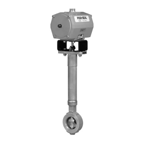
This instruction manual provides installation, maintenance, and parts ordering information for the POSI-SEAL A31A
Cryogenic high-performance butterfly valves (see figure 1). The Series C (3- through 6-inch Class 150 & 300 and 8-inch
Class 150) feature a cast one-piece extension. The 8-inch Class 300, and 10- through 24-inch Class 150 & 300 designs
have a two-piece extension. For information regarding actuators and accessories, refer to separate instruction
manuals.
Do not install, operate, or maintain an A31A Cryogenic valve without being fully trained and qualified in valve,
actuator, and accessory installation, operation, and maintenance. To avoid personal injury or property damage, it is
important to carefully read, understand, and follow all of the contents of this manual, includingall safety cautions and
warnings. If you have any questions about these instructions, contact your
www.Fisher.com
A31A Cryogenic High
™
. . . . .
. . . . . . . . . . . . . . . . . . . . . .
. . . . . . . . . . . . . . . . . . .
. . . . . . . . . . . . . . . . .
. . . . . . . . . .
. . . . . . . . . . . . .
. . . . . . . . . . . . . . . .
. .
. . . . . . . . . . . . . . .
. . . . . . . . . . . . . . .
. . . . . . . . . . . . .
Figure 1. Fisher A31A Cryogenic Valve with
1035 Actuator
1
1
2
2
2
4
4
4
6
8
8
9
10
11
12
13
15
16
18
19
21
W7451 / IL
22
22
Emerson sales
A31A Cryogenic-Rotary Valve
February 2019
office.
Advertisement
Table of Contents

Related Manuals for Emerson Fisher POSI-SEAL A31A


Summary of Contents for Emerson Fisher POSI-SEAL A31A
-
Page 1: Table Of Contents
To avoid personal injury or property damage, it is important to carefully read, understand, and follow all of the contents of this manual, includingall safety cautions and warnings. If you have any questions about these instructions, contact your Emerson sales office. www.Fisher.com... -
Page 2: Specifications
Instruction Manual A31A Cryogenic-Rotary Valve February 2019 D500242X012 Table 1. Specifications Available Valve Configurations pressure/temperature rating is the same as the valve body. See figure 2 for rating of Kel‐F seal. J Flangeless, wafer‐style or J single‐flange (lugged) control valve with a one‐piece extension housing and Valve Classification either NOVEX seal (standard), Kel‐F seal (optional) or Face‐to‐face dimensions are in compliance with MSS... - Page 3 Because pressure drop and temperature range capabilities limit some combinations of materials, do not apply any other conditions to the valves without first contacting your Emerson sales office. Before installation check the maximum allowable inlet pressures for A31A Cryogenic valves shown in figure 2 and the Specifications table.
-
Page 4: Adjusting The Actuator Travel Stops Or Travel
Instruction Manual A31A Cryogenic-Rotary Valve February 2019 D500242X012 Adjusting the Actuator Travel Stops WARNING The edges of a rotating valve disk have a shearing effect that may result in personal injury. To avoid personal injury, keep clear of the disk edges when rotating the disk. CAUTION When using an actuator, the actuator travel stops or the actuator travel (for actuators without adjustable stops) must be adjusted so that the disk stop in the valve body does not absorb the output of the actuator. - Page 5 Instruction Manual A31A Cryogenic-Rotary Valve D500242X012 February 2019 valve into the fully closed position. Then, take appropriate steps to ensure that the actuator does not cause the valve to open during installation. 1. The A31A Cryogenic valve is normally shipped as part of an assembly with an actuator and other accessories. If the valve and actuator have been purchased separately or if the actuator has been removed for maintenance, properly mount the actuator and adjust valve/actuator travel and all travel stops before inserting the valve into the line.
-
Page 6: Installing Wafer-Style Valves
Instruction Manual A31A Cryogenic-Rotary Valve February 2019 D500242X012 Table 3. Valve Body Data, Class 300 APPROXIMATE WEIGHT SHAFT DIAMETER AT FACE‐TO‐FACE DIMEN‐ MINIMUM .(2) YOKE BEARING SION Wafer Single Flange VALVE SIZE, INCHES Kilograms 47.6 71.4 54.0 93.7 57.2 146.1 73.0 186.2 85.3... - Page 7 Instruction Manual A31A Cryogenic-Rotary Valve D500242X012 February 2019 Table 4. Hex Head Screw, Stud Bolt and Cap Screw Data NUMBER SIZE DIA. INCH & THREAD LENGTH, INCH VALVE SIZE, INCH Class 150 Class 300 Class 150 Class 300 Class 150 Class 300 Wafer Style with Stud Bolts 5/8‐11...
-
Page 8: Installing Single-Flange Valves
Instruction Manual A31A Cryogenic-Rotary Valve February 2019 D500242X012 5. For more information, refer to the Packing Maintenance section below. Installing Single‐Flange Valves WARNING The edges of a rotating valve disk have a shearing effect that may result in personal injury. To avoid personal injury, keep clear of the disk edges when rotating the disk. -
Page 9: Replacing Packing
Instruction Manual A31A Cryogenic-Rotary Valve D500242X012 February 2019 D Check with your process or safety engineer for any additional measures that must be taken to protect against process media. Figure 3. Properly Installed Cryogenic Valve COLD BOX TRANSITION 4” ‐ 8” MIN 20_ MIN 16B5084 / DOC Replacing Packing... -
Page 10: Removing The Valve From The Pipeline
Instruction Manual A31A Cryogenic-Rotary Valve February 2019 D500242X012 1. Before loosening any parts, isolate the valve from the line pressure, release pressure from both sides of the valve body, and drain the process media from both sides of the valve. 2. -
Page 11: Removing/Installing The Seal Ring
Instruction Manual A31A Cryogenic-Rotary Valve D500242X012 February 2019 Removing/Installing the Seal Ring Unless otherwise indicated, key numbers and part names are listed in figures 7 and 8. Note For valves large enough to be safely placed on a flat surface without tipping, it is possible to replace the seal ring (key 7) while the actuator is mounted to the valve and can be accomplished by cycling the valve to 90 degrees open. -
Page 12: Novext Seal Installation
Unless otherwise indicated, key numbers and part names are listed in figures 7 and 8. Seal installation is shown in figure 5. A maintenance kit with installation tools is available through your Emerson sales office. 1. Locate the replacement seal ring (key 7) and note the shape of the ring. The ring is wider across one edge diameter and narrower across the other edge diameter. -
Page 13: Kel-F And Kel-F/Aluminum Seal Installation
The internal travel stop in the valve body should not absorb any of the actuator torque. Kel‐F and Kel‐F/Aluminum Seal Installation Unless otherwise indicated, key numbers and part names are listed in figures 7 and 8. A maintenance kit with installation tools is available through your Emerson sales office. - Page 14 1000 Note: These values are based upon standard materials, S66286/Inconel screws and ASTM A193GRB6 bolts. For other special fastener materials, please contact your Emerson sales office. 2. Install the seal ring, and if applicable back‐up ring, in the valve body by first placing the wider outside diameter of the seal ring into the T‐slot area of the valve body as shown in figure 5.
-
Page 15: Anti-Blowout Protection, Packing, Valve Shaft(S), Disk, And Bearing Maintenance
Instruction Manual A31A Cryogenic-Rotary Valve D500242X012 February 2019 4. Install the retaining ring, and align the screw holes in the retaining ring with the holes in the valve body. Install the first retaining ring screw through the punched hole in the retaining ring gasket. Install the other retaining ring screws by pushing them through the graphite gasket and threading them into the valve body. -
Page 16: Disassembly
Instruction Manual A31A Cryogenic-Rotary Valve February 2019 D500242X012 Figure 6. Anti‐Blowout Protection Detail SHAFT SHAFT STUD HEX NUT PACKING PACKING FLANGE FOLLOWER ANTI‐BLOWOUT STUD FLANGE PACKING V‐RING PACKING RING PACKING OUT'BD BEARING SHAFT SHOULDER ANTI‐BLOWOUT FOLLOWER SHAFT SHOULDER TYPICAL PTFE V‐RING A7090 / IL PACKING... - Page 17 Class 150 and 300 3‐ through 24‐inch valve sizes have a bearing stop pressed into the bearing bore of the valve body below the extension housing. Do not attempt to remove the bearing stop. If the bearing stop needs replacement, contact your Emerson sales office for more information.
-
Page 18: Installing A One-Piece Shaft
Instruction Manual A31A Cryogenic-Rotary Valve February 2019 D500242X012 c. Use a threaded rod with an appropriate spacer and nut as an extractor tool. If using a threaded rod, choose a rod with threads that fit the inside thread of the pins. The rod should extend several inches above the disk when it is screwed into a pin. -
Page 19: Installing A Two-Piece Shaft
Instruction Manual A31A Cryogenic-Rotary Valve D500242X012 February 2019 5. Insert the outboard journal bearing (key 10) into the bore on top of the extension housing. 6. Install the valve disk by placing the disk into the valve body bore so the curved side of the disk passes through the end of the valve body that does not contain the T‐slot. - Page 20 Instruction Manual A31A Cryogenic-Rotary Valve February 2019 D500242X012 3. Using caution to prevent damage to the bearings, insert the required number of journal bearings (key 9) from the valve body bore into the drive shaft bearing bore. When properly installed, one end of the journal bearing(s) will be flush with the interior end of the extension housing, the other end of the journal bearing(s) will be flush with the valve body bore.
-
Page 21: Installing The Gasket Retainer
Instruction Manual A31A Cryogenic-Rotary Valve D500242X012 February 2019 13. After driving the taper key in place, arc spot weld the head of the taper key to the disk. For valve sizes 8‐, 10‐ and 12‐inch, use an arc spot weld bead of 3/16‐inch in diameter. 14. -
Page 22: Parts Ordering
Emerson sales office. WARNING Use only genuine Fisher replacement parts. Components that are not supplied by Emerson Automation Solutions should not, under any circumstances, be used in any Fisher valve, because they may void your warranty, might adversely affect the performance of the valve, and could cause personal injury and property damage. - Page 23 Instruction Manual A31A Cryogenic-Rotary Valve D500242X012 February 2019 Figure 7. Fisher A31A Cryogenic 3 through 12‐inch Typical Assembly 16B5086 / DOC...
- Page 24 Instruction Manual A31A Cryogenic-Rotary Valve February 2019 D500242X012 Figure 7. Fisher A31A Cryogenic 3 through 12‐inch Typical Assembly (continued) ASSEMBLY 16B5085 / DOC 16B5087 / DOC...
- Page 25 Instruction Manual A31A Cryogenic-Rotary Valve D500242X012 February 2019 Figure 8. 14‐ through 24‐Inch Fisher A31A Cryogenic Valves (Wafer Style Shown) (Shown without 2‐piece Extension Housing) ANTI‐BLOWOUT FLANGE ANTI‐BLOWOUT FLANGE NUT B2388/IL...
- Page 26 Instruction Manual A31A Cryogenic-Rotary Valve February 2019 D500242X012...
- Page 27 Instruction Manual A31A Cryogenic-Rotary Valve D500242X012 February 2019...
- Page 28 Responsibility for proper selection, use, and maintenance of any product remains solely with the purchaser and end user. POSI‐SEAL, NOVEX, and Fisher are marks owned by one of the companies in the Emerson Automation Solutions business unit of Emerson Electric Co.