Table of Contents
Advertisement
Instruction Manual
D103302X012
r
Fisher
POSI-SEAL
Contents
. . . . . . . . . . . . . . . . . . . . . . . . . . . . . . . . . . .
. . . . . . . . . . . . . . . . . . . . . . . . . . . .
. . . . . . . . . . . . . . . . . . . . . . . . . . . . . . .
. . . . . . . . . . . . . . . . . . . . . . . . . . . . . . . . .
. . . . . . . . . . . . . . . . . . . . . . . . . . . . . . . . . . . .
. . . . . . . . . . . . . . . . . . . . . . . . . . . . . . . . . .
. . . . . . . . . . . . . . . . . . . . . . . . .
. . . . . . . . . . . . . . . . . . . . . . . . . . . . . . . .
. . . . . . . . . . . . . . . . . . . . . . . . . . . . . . . . . . .
. . . . . . . . . . . . . . . . . . . . . . . . . . . . . . . . . . .
Introduction
Scope of Manual
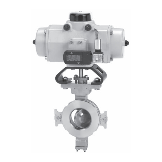
This instruction manual includes installation, maintenance, and parts information for the Fisher POSI-SEAL A81 valve,
DN50 through DN300 or NPS 2 through NPS 12 (figure 1). Refer to separate instruction manuals for information
covering the power on-off actuator and accessories.
Do not install, operate, or maintain an A81 valve without being fully trained and qualified in valve, actuator, and
accessory installation, operation, and maintenance. To avoid personal injury or property damage, it is important to
carefully read, understand, and follow all the contents of this manual, including all safety cautions and warnings. If you
have any questions about these instructions, contact your Emerson Process Management sales office before
proceeding.
www.Fisher.com
t
A81 Rotary Valve
. . . . . . . . . . . . . . . . . . . . . . . .
. . . . . . . . . . . . . .
. . . . . . . . . .
Figure 1. Fisher A81 Valve with FieldQ™ Actuator
1
1
2
4
4
8
9
12
13
18
18
19
20
W9479
A81 Valve
January 2011
Advertisement
Table of Contents

Related Manuals for Emerson Fisher POSI-SEAL A81


Summary of Contents for Emerson Fisher POSI-SEAL A81
-
Page 1: Table Of Contents
To avoid personal injury or property damage, it is important to carefully read, understand, and follow all the contents of this manual, including all safety cautions and warnings. If you have any questions about these instructions, contact your Emerson Process Management sales office before proceeding. -
Page 2: Specifications
Instruction Manual A81 Valve January 2011 D103302X012 Table 1. Fisher A81 Valve Specifications Specifications ASME Valve Body Size DN 50, 80, 100, 150, 200, 250, and 300 NPS 2, 3, 4, 6, 8, 10, and 12 Pressure Rating PN 10 to 40 per EN 12516‐1 CL150 and 300 per ASME B16.34 EN 1.0619 steel WCC steel... - Page 3 1. Minimum allowable temperature for PN series flanges is -10_C (14_F). See requirements of EN 13445‐2 Annex B for applications below -10_C (14_F) with PN series flanges. 2. For applications exceeding 316_C (600_F), consult your Emerson Process Management sales office for appropriate disk material selection.
-
Page 4: Description
Emerson Process Management sales office. The maximum allowable inlet pressures for steel and stainless steel valve bodies are consistent with the pressure‐temperature ratings shown in table 1, except where further limited by the trim and packing material... - Page 5 Instruction Manual A81 Valve D103302X012 January 2011 the measurements that must be made during the actuator adjustment process. Refer to the Actuator Mounting section on page 18 of this manual and to the separate actuator instruction manual for mounting and adjusting instructions before proceeding.
- Page 6 Instruction Manual A81 Valve January 2011 D103302X012 Table 5. Stud Bolt Data WAFER STYLE VALVE SIZE PN 10 PN 16 PN 25 PN 40 Size Dia Size Dia Size Dia Size Dia No. of No. of No. of No. of &...
- Page 7 Instruction Manual A81 Valve D103302X012 January 2011 WARNING An A81 valve body is not necessarily grounded when installed in a pipeline. If the valve is used in a flammable or hazardous atmosphere or for oxygen service, an explosion could result due to a discharge of static electricity from the valve components.
-
Page 8: Maintenance
Instruction Manual A81 Valve January 2011 D103302X012 Figure 4. Packing Arrangement Details PTFE V‐RING GRAPHITE RIBBON GE39986‐A GE39901‐A STANDARD PACKING GE40113‐A GE40118‐A SINGLE PTFE PACKING GRAPHITE PACKING ENVIRO‐SEAL PACKING NOTES: THESE TWO SURFACES SHOULD REMAIN PARALLEL AS YOU ALTERNATELY AND EVENLY WITH CONDUCTIVE PACKING, THE FEMALE ADAPTOR IN PTFE V‐RING PACKING TIGHTEN THE PACKING NUTS (KEY 28). -
Page 9: Packing Maintenance
Instruction Manual A81 Valve D103302X012 January 2011 WARNING Avoid personal injury and property damage from sudden release of process pressure or bursting of parts. Before performing any maintenance operations: D Do not remove the actuator from the valve while the valve is still pressurized. D Always wear protective gloves, clothing, and eyewear when performing any maintenance operations. - Page 10 Instruction Manual A81 Valve January 2011 D103302X012 For valves with the ENVIRO‐SEAL packing system: Optimum performance of the ENVIRO‐SEAL packing system is obtained when the Belleville springs are tightened to their “target load.” The target load is the point where the springs are compressed to 85% of their maximum deflection, or nearly flat.
- Page 11 Instruction Manual A81 Valve D103302X012 January 2011 2. Remove the actuator per instructions in separate actuator instruction manuals, then remove the cap screws and nuts (keys 35 and 36). Remove the clamp (key 130, figure 3) if the strap (key 131, figure 3) is used. 3.
-
Page 12: Replacing The Seal Ring Assembly
Instruction Manual A81 Valve January 2011 D103302X012 Figure 5. Orientation of Bearing Tabs BACKSIDE OF VALVE BEARING TAB BEARING TAB 3. Loosen the two packing hex nuts evenly to remove spring tension, then remove the nuts. 4. Remove the packing flange and spring pack assembly. The spring pack assembly consists of the spring stack and packing follower. -
Page 13: Replacing The Disk, Shafts, Or Bearings
Instruction Manual A81 Valve D103302X012 January 2011 Key numbers in this procedure are shown in figure 9 unless otherwise indicated. 1. Isolate the control valve from line pressure, and relieve pressure from the valve body. Shut off and disconnect all lines from the power actuator. - Page 14 Instruction Manual A81 Valve January 2011 D103302X012 1. Isolate the control valve from the line pressure, release pressure from both sides of the valve body, and drain the process media from both sides of the valve. If using a power actuator, also shutoff all pressure lines to the power actuator, release all pressure from the actuator.
- Page 15 Instruction Manual A81 Valve D103302X012 January 2011 Assembly WARNING Do not lubricate bearings that will be used for oxygen service, or where the lubrication is incompatible with the process media. Any use of lubricant can lead to the sudden explosion of media due to the oil/oxygen mixture, causing personal injury or property damage.
- Page 16 Instruction Manual A81 Valve January 2011 D103302X012 Figure 7. Sectional of Typical Valve Body ACTUATOR END OF SHAFT CCW DISK ROTATION TO OPEN POSITION INDICATION MARK INDICATES APPROXIMATE DISK POSITION Figure 8. Follower Spring/Spring Seat Assembly FOLLOWER SPRING SEAT (KEY 9) FOLLOWER SPRING (KEY 12) FOLLOWER SPRING SEAT...
- Page 17 Instruction Manual A81 Valve D103302X012 January 2011 1. If new bearings (key 6) are required, install and orient them in the valve body, as shown in figure 5. Ensure the bearings are fully seated, contacting the inside diameter of the valve body. 2.
-
Page 18: Actuator Mounting
Note Neither Emerson, Emerson Process Management, nor any of their affiliated entities assumes responsibility for the selection, use, or maintenance of any product. Responsibility for the selection, use, and maintenance of any product remains with the purchaser and... -
Page 19: Parts Kits
A81 valve are included in the kits. Worn shafts, packing box damage, or other components that do not meet Emerson Process Management finish specifications, dimensional tolerances, and design specifications, may adversely alter the performance of the retrofit kit. -
Page 20: Parts List
DN 200 and 250 (NPS 8 and 10) GE28145X042 Note DN 300 (NPS 12) GE20539X022 S20910 For part numbers not shown, contact your Emerson Process DN 50 (NPS 2) GE27079X012 Management sales office. DN 80 (NPS 3) GE21165X012 DN 100 (NPS 4) GE23792X012 DN 150 (NPS 6) - Page 21 Instruction Manual A81 Valve D103302X012 January 2011 Figure 9. Fisher A81 Valve Assembly GE27325_D...
- Page 22 Instruction Manual A81 Valve January 2011 D103302X012 Figure 10. Fisher A81 Seal Assembly Detail FLOW RING CONSTRUCTION SOFT SEAL CONSTRUCTION METAL SEAL CONSTRUCTION ASSEMBLY ASSEMBLY ASSEMBLY GE27325_D_2 Description Part Number Description Part Number 24* Packing Ring (4 req'd) DN 100 (NPS 4) 12B7418X012 Graphite ribbon DN 150 (NPS 6)
- Page 23 Instruction Manual A81 Valve D103302X012 January 2011...
- Page 24 Fisher, POSI-SEAL, FieldQ, and ENVIRO‐SEAL are marks owned by one of the companies in the Emerson Process Management business division of Emerson Electric Co. Emerson Process Management, Emerson, and the Emerson logo are trademarks and service marks of Emerson Electric Co. All other marks are the property of their respective owners.