Advertisement
Table of Contents
- 1 Table of Contents
- 2 General Valve Description and Start-Up
- 3 Main Valve Maintenance
- 4 Pilot Maintenance
- 5 Pilot Set Pressure Adjustment
- 6 Valve Assembly Testing
- 7 Pilot Set Pressure Field Test Procedure
- 8 Soft Goods Repair Kits
- 9 Pilot Accessories
- 10 Assembly and Maintenance Equipment
- Download this manual
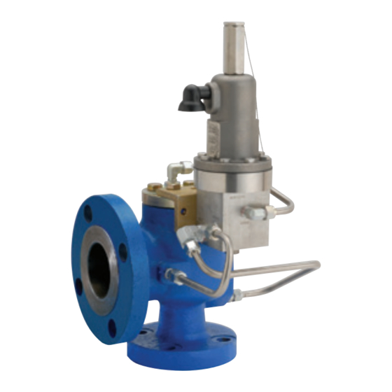
Anderson Greenwood SerieS 400 PiSton Pilot PoPrV
InstallatIon and MaIntenance InstructIons
Before installation these instructions must be fully read and understood
tAble oF Contents
1
2
Main valve maintenance .............................. 2
3
Pilot maintenance ........................................ 7
4
Pilot set pressure adjustment .................. 14
5
Valve assembly testing .............................. 20
6
7
Soft goods repair kits................................. 25
8
Pilot accessories ........................................ 26
9
1 GenerAl vAlve desCription And
stArt-up
1.1 General
the Anderson Greenwood Series 400 valve is
designed for modulating action. the main valve
will open at nameplate set, but only an amount
proportional to the relieving capacity required.
As process pressure increases, the valve will
open more and be in full lift at 110% of set.
the main valve uses the principle of
pressurizing the top or large area of a
differential area piston with line pressure
to hold the piston closed up to set
pressure. At set pressure, the pilot relieves,
depressurizing the volume above the piston,
the main valve dome, and the piston lifts
permitting discharge from the main valve.
emerson.com/FinalControl
As capacity relief of the system is satisfied,
system pressure will begin to decrease. When
it does, the pilot will actuate and direct system
pressure to the main valve dome. this closes
the main valve.
the pilot is the non-flowing type. With the main
valve open and relieving at steady pressure,
no process gas or fluid flows through the pilot.
When process pressure changes, the pilot
actuates to change the lift of the main valve
piston. During these actuations a small amount
of gas or fluid from the main valve dome flows
through the pilot and is discharged thru the
pilot exhaust.
the set pressure range is 100 psig to 1480 psig.
1.2 installation
either or both inlet and outlet may be
standard AnSi flanges or AnSi pipe threaded
connections and are to be installed in
accordance with accepted piping practices.
When remote pressure pick-up is used the pilot
supply tube is connected to a remote location
rather than to the inlet neck of the valve. A
block valve in the remote pilot supply line is not
recommended. if one is used it must be opened
before pressurizing the main valve.
note
remote pressure pick-up piping must have the
equivalent flow area of 3/8" tubing for lengths up to
100 feet. For lengths greater than this, consult factory.
1.3 start-up
there must be pressure at the valve inlet or at
the pilot inlet/sense port for valves with remote
sense to establish a differential force across
the piston and 'load' it in the closed position.
Pressure must pass through the pilot and exert
force on the top of the piston. on normal plant
start-up the valve will close itself as pressure
increases.
Block valves are often used under safety valves
to isolate them when maintenance is required.
When putting the safety valve in service be sure
the block valve is fully opened. if the block valve
is opened after system start-up, the safety
valve may briefly vent before the dome gets
pressurized to close the main valve seat.
© 2017 emerson. All rights reserved.
engineering Doc. #05.9040.270 rev. K
vCioM-06020-en 18/02
Advertisement
Table of Contents

Related Manuals for Emerson Anderson Greenwood Type 443


Summary of Contents for Emerson Anderson Greenwood Type 443
-
Page 1: Table Of Contents
Doc. #05.9040.270 rev. K emerson.com/FinalControl vCioM-06020-en 18/02 © 2017 emerson. All rights reserved. -
Page 2: Main Valve Maintenance
Anderson Greenwood SerieS 400 PiSton Pilot PoPrV InstallatIon and MaIntenance InstructIons 1.4 Maintenance 2.2 Main valve nozzle rework note Anderson Greenwood recommended main valve Should the main valve nozzle seating face Do not remove lock pin and lift adjusting bolt (items 11 and pilot maintenance procedures including become nicked or scratched such that the main and 12) on valves so equipped unless nozzle is... - Page 3 Anderson Greenwood SerieS 400 PiSton Pilot PoPrV InstallatIon and MaIntenance InstructIons 2.3 Assembly on 1” to 4” type 43/53 and 1.5” to 3” type 63 2.3.1 Nozzle and nozzle seal installation valves, if either or both the nozzle and lift bolt 1.
- Page 4 Anderson Greenwood SerieS 400 PiSton Pilot PoPrV InstallatIon and MaIntenance InstructIons tAble ii pArts list 2.3.4 Type XX9 piston and seat Clean and apply a light coating of Dow Corning bolt size torque value (ft·lbs) item no. part name no. 33 or equivalent silicone lubricant on all ¼...
- Page 5 Anderson Greenwood SerieS 400 PiSton Pilot PoPrV InstallatIon and MaIntenance InstructIons see detail A detail A With wedge ring detail A Without wedge ring FiGUre 1B - MAin VAlVe 449/459/469 pArts list item no. part name item no. part name notes Body lock pin...
- Page 6 Anderson Greenwood SerieS 400 PiSton Pilot PoPrV InstallatIon and MaIntenance InstructIons Cap bolt Spacer liner Piston nozzle retainer nozzle nozzle seal Body FiGUre 2...
-
Page 7: Pilot Maintenance
Anderson Greenwood SerieS 400 PiSton Pilot PoPrV InstallatIon and MaIntenance InstructIons 3 pilot MAintenAnCe 3.1.2 Iso-Dome pilot – gas service Refer to Figures 3, 4, and 5. note All iso-Dome pilots are gas service pilots; however, Arrange all parts in an orderly sequence on fully assembled valves with these pilots may be either a flat work surface during disassembly. - Page 8 Anderson Greenwood SerieS 400 PiSton Pilot PoPrV InstallatIon and MaIntenance InstructIons 3.1.4 Pilot variations and accessories 3.2.2 Iso-Dome pilot – gas service For pilot equipped with a one-piece spool, Figure 3 All iso-Dome pilots are gas service pilots Style A, remove the spool seal (item 28) and the (see note paragraph 3.1.2).
- Page 9 Anderson Greenwood SerieS 400 PiSton Pilot PoPrV InstallatIon and MaIntenance InstructIons 3.2.3 Accessories Do not get any lubricant on the shuttle, shuttle Assembly is done in the reverse order seat(s) and or bushing seat. When re-installing of disassembly. on backflow preventers the backflow preventer on the main valve dome (reference Figures 4 and 5), lightly lubricate port orient it so that the bushing is connected to...
- Page 10 Anderson Greenwood SerieS 400 PiSton Pilot PoPrV InstallatIon and MaIntenance InstructIons lift lever assembly iso-dome pilot assembly FiGUre 3 - Pilot (Continued from page 9)
- Page 11 Anderson Greenwood SerieS 400 PiSton Pilot PoPrV InstallatIon and MaIntenance InstructIons pArts list item description item description Body Seal, lower outlet nozzle Plug, body Seat, outlet Piston, feedback Spool Plate, piston Seal, sense piston nozzle, inlet Screen, inlet Spring Plug, body f.t. port Seat, inlet Vent, exhaust port Spring, spool...
- Page 12 Anderson Greenwood SerieS 400 PiSton Pilot PoPrV InstallatIon and MaIntenance InstructIons Dome connection port Plunger spring Spring* Dome connector Plunger seal Field test body Shuttle seal Plunger Plunger seat Shuttle* view A - A FiGUre 4 - FielD teSt ACCeSSory * Spring based shuttle design standard from July 1st, 2002...
- Page 13 Anderson Greenwood SerieS 400 PiSton Pilot PoPrV InstallatIon and MaIntenance InstructIons Main valve backflow preventer Pilot Dome connection Main valve outlet Pilot exhaust backflow check valve backflow preventer connection Main valve inlet Bushing seat Body Bushing seal Bushing seal Shuttle Shuttle seat Shuttle Shuttle seat...
-
Page 14: Pilot Set Pressure Adjustment
Anderson Greenwood SerieS 400 PiSton Pilot PoPrV InstallatIon and MaIntenance InstructIons 4 pilot AdjustMent increase the air supply pressure to nameplate setting and slowly back out the adjustment 4.1 definitions screw until water flow through the pilot set pressure is defined as the supply pressure exhaust begins. - Page 15 Anderson Greenwood SerieS 400 PiSton Pilot PoPrV InstallatIon and MaIntenance InstructIons 4.3 set pressure, iso-dome pilot 4.3.2 Liquid sense pilot to adjust the set pressure, a test set-up similar to that shown in Figure 9 should be used. note the air supply to the regulator inlet should All iso-Dome pilots are gas service pilots be adjusted so that the dome pressure gauge (See note paragraph 3.1.2).
- Page 16 Anderson Greenwood SerieS 400 PiSton Pilot PoPrV InstallatIon and MaIntenance InstructIons 4.6 lift lever handle assembly installation occurred. if resistance occurs at less than 15°, For pilot equipped with a lift lever, install the lift lever nut must be positioned higher. if the lift lever handle assembly (item 42) after resistance first occurs at more than 45°, the completing the final pilot adjustment.
- Page 17 Anderson Greenwood SerieS 400 PiSton Pilot PoPrV InstallatIon and MaIntenance InstructIons Set pressure adjustment (turn in to increase set pressure) (turn out to decrease set pressure) Bleed valve Dome pressure gauge Shut-off valve (optional) Pilot exhaust Flexible hose indicator assembly (optional) (to inlet port) indicator optional indicator Solid bar w/threaded ends...
- Page 18 Anderson Greenwood SerieS 400 PiSton Pilot PoPrV InstallatIon and MaIntenance InstructIons Set pressure adjustment (turn in to increase set pressure) (turn out to decrease set pressure) Bleed valve Pilot exhaust Dome pressure gauge Flexible hose Block valve Air supply (regulator inlet) regulator Flexible hose (to inlet port) Supply pressure gauge Shut-off valve...
- Page 19 Anderson Greenwood SerieS 400 PiSton Pilot PoPrV InstallatIon and MaIntenance InstructIons Set pressure adjustment (turn in to increase set pressure) (turn out to decrease set pressure) Bleed valve Dome pressure gauge Shut-off valve (optional) Pilot exhaust Flexible hose Block valve indicator assembly (optional) Air supply (regulator indicator...
-
Page 20: Valve Assembly Testing
Anderson Greenwood SerieS 400 PiSton Pilot PoPrV InstallatIon and MaIntenance InstructIons 5 vAlve AsseMbly testinG 5.3 High pressure leakage check 5.1 General note the complete valve assembly should be tested For valve with iso-Dome pilot, apply regulator supply for internal and external leakage and to verify pressure equal to a minimum of 200 psi greater than set pressure using a test set-up similar to that 92% of set pressure. - Page 21 Anderson Greenwood SerieS 400 PiSton Pilot PoPrV InstallatIon and MaIntenance InstructIons 5.4 Main valve function check CAution This test must be performed at a slow rate of pressure increase to ensure that the main valve ¼” o.D. X .028 wall tube does not go into full lift.
- Page 22 Anderson Greenwood SerieS 400 PiSton Pilot PoPrV InstallatIon and MaIntenance InstructIons ¼” o.D. X .028 wall tube ¼” i.D. flexible elastomer or rubber tubing Ported blind flange Supply pressure gauge Supply FiGUre 11 - teSt Set-UP For VAlVe WitH reMote SenSe Pilot iso-Dome pilot ¼”...
- Page 23 Anderson Greenwood SerieS 400 PiSton Pilot PoPrV InstallatIon and MaIntenance InstructIons 5.7 iso-sense pilot operated pressure relief valve in this special pilot operated pressure relief iso-Sense pilot valve, the sense pressure applied to the pilot inlet/sense port is supplied from a remote source and the sense pressure media is isolated from the process media.
-
Page 24: Pilot Set Pressure Field Test Procedure
Anderson Greenwood SerieS 400 PiSton Pilot PoPrV InstallatIon and MaIntenance InstructIons 6 pilot set pressure Field test Gas vent proCedure (indicator plunger) 6.1 General Field test CAution test gauge alternate location If the pressure relief valve is not isolated from Flexible hose the process media while performing this test, the main valve will open if system pressure rises to set point or above. -
Page 25: Soft Goods Repair Kits
Anderson Greenwood SerieS 400 PiSton Pilot PoPrV InstallatIon and MaIntenance InstructIons 7 soFt Goods repAir kits valve model and serial number. For soft goods kits with elastomers other than those listed, the kits listed below are available from stock. contact Anderson Greenwood or an authorized each kit contain all the seals and seats to representative. -
Page 26: Pilot Accessories
Anderson Greenwood is a mark owned by one of the companies in the emerson Automation Solutions business unit of emerson electric Co. emerson Automation Solutions, emerson and the emerson logo are trademarks and service marks of emerson electric Co.