
Related Manuals for MSI MS-6533E


Summary of Contents for MSI MS-6533E
- Page 1 MICRO-STAR INTERNATIONAL MS-6533E/G/EG (v1.X) Micro ATX Mainboard Version 1.0 G52-MA00628...
- Page 2 Manual Rev: 1.0 Release Date: July 2002 FCC-B Radio Frequency Interference Statement This equipment has been tested and found to comply with the limits for a class B digital device, pursuant to part 15 of the FCC rules. These limits are designed to provide reasonable protection against harmful interference when the equip- ment is operated in a commercial environment.
- Page 3 Edition July 2002 Copyright Notice The material in this document is the intellectual property of MICRO-STAR INTERNATIONAL. We take every care in the preparation of this document, but no guarantee is given as to the correctness of its contents. Our products are under continual improvement and we reserve the right to make changes without notice.
- Page 4 Safety Instructions Read the safety instructions carefully. Save this User’s Guide for possible use later. Keep this equipment away from humidity. Lay this equipment on a stable and flat surface before setting it up. The openings on the enclosure are used for air convection and to prevent the equipment from overheating.
-
Page 5: Table Of Contents
CONTENTS Chapter 1. Getting Started ................ 1-1 Mainboard Specification ..............1-2 Mainboard Layout ................1-5 Quick Components Guide ..............1-8 Chapter 2. Hardware Setup ............... 2-1 Central Processing Unit: CPU .............. 2-2 CPU Installation Procedures ............2-2 Installing the CPU Fan ..............2-3 CPU Core Speed Derivation Procedure ......... - Page 6 Hard Disk Connectors: IDE1 & IDE2 ........... 2-14 JCD1/JAUX1/JMD1 ..............2-15 CPUFA/SYSFA ................2-16 Front Panel Connectors: JFP1 & JFP2 ......... 2-17 Front Panel Audio Connector: JAUD .......... 2-18 Front USB Connectors: JUSB2 & JUSB3 ........2-19 IrDA Infrared Module Header: JIR ..........2-20 LAN Active LED Jumper: JLAN ..........
- Page 7 PNP/PCI Configurations ..............3-24 PC Health Status ................3-26 Frequency/Voltage Control ..............3-27 Load Fail-Safe/Optimized Defaults ............. 3-29 Set Supervisor/User Password ............3-30 Appendix: Using 4- or 6-Channel Audio Function ........A-1 Installing the Audio Driver ..............A-2 Using 4- or 6- Channel Audio Function ..........A-4 Selecting 4- or 6- Channel Setting ............
-
Page 8: Chapter 1. Getting Started
Getting Started Chapter 1. Getting Started Getting Started Thank you for purchasing the MS-6533E/G/EG series Micro ATX mainboards. The MS-6533E/G/EG series are based on SiS645DX/SiS650GX/ SiS651 (co-layout) and SiS962L/SiS962 chipsets for optimal system efficiency. Designed to fit the advanced Intel... -
Page 9: Mainboard Specification
Chapter 1 Mainboard Specification Socket 478 for P4 processors (Willimate 478 and Northwood 478) with 400/ 533 MHz (100/133MHz QDIR) Core frequency from 1.7GHz to 2.53 GHz and up Chipset 645DX/650GX/651 HMAC/IGUI HMAC /IGUI HMAC (702 pin BGA) ® - High performance host interface 400/533 (645 DX and 651 only) MHz - Support 64-bit high performance DDR333 (645 DX and 651 only) / DDR266/DDR 200 and PC133/100 memory controller - Support AGP 4X/2X interface with fast write transaction... - Page 10 Supports Wake-On-LAN and remote wake-up. Supports ACPI power management. Modem (optional) Supports MSI proprietary modem card MS-6961. IEEE 1394 (SiS 962 only) (optional) Compliant with IEEE 1394-1995 and 1394a-2000 Supports Serial Bus Data Rates of 100, 200 and 400 Mbits/s.
- Page 11 Chapter 1 BIOS 2Mb Award BIOS with PnP, ACPI, SMBIOS 2.3, Green and Boot Block. Provides DMI2.0, WfM2.0, WOL, WOR, chassis intrusion, and SMBus for system management. Dimension Micro ATX Form Factor: 9.6” x 9.6”. Mounting 6 mounting holes.
-
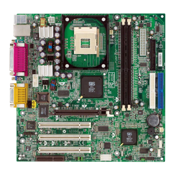
Page 12: Mainboard Layout
Getting Started Mainboard Layout JPW1 Top : mouse Bottom: keyboard Top: LAN Jack CPUFA Bottom: USB ports Top : Parallel Port Bottom: COM A COM B Top : Game port 645DX Bottom: Line-Out BIOS Line-In JA UX1 AGP Slot Winbond JC D1 W83697HF BATT... - Page 13 Chapter 1 Mainboard Layout JPW1 Top : mouse Bottom: keyboard Top: LAN Jack CPUFA Bottom: USB ports Top : Parallel Port Bottom: COM A VGA port JCOM3 Top : Game port 650GX Bottom: Line-Out BIOS Line-In JA UX1 AGP Slot Winbond JC D1 W83697HF...
- Page 14 Getting Started Mainboard Layout JPW1 Top : mouse Bottom: keyboard Top: LAN Jack CPUFA Bottom: USB ports Top : Parallel Port Bottom: COM A VG A port JCOM3 Top : Game port Bottom: Line-Out BIOS Line-In JAUX1 AGP Slot Winbond JCD1 W83697HF BATT...
-
Page 15: Quick Components Guide
Chapter 1 Quick Components Guide Component Function Reference CONN1/JPW1 Power connectors See p. 2-7 JKBMS1 Mouse connector See p. 2-8 JKBMS1 Keyboard connector See p. 2-9 USB Connectors Connecting to USB devices See p. 2-9 COMA & COMB/JCOM3 Serial port connectors See p. -
Page 16: Chapter 2. Hardware Setup
Hardware Setup Chapter 2. Hardware Setup Hardware Setup This chapter provides you with the information about hardware setup procedures. While doing the installation, be careful in holding the components and follow the installation procedures. For some components, if you install in the wrong orientation, the components will not work properly. -
Page 17: Cpu Installation Procedures
Chapter 2 CPU Installation Procedures for Socket 478 Open Lever Please turn off the power and unplug the power cord before Sliding 90 degree Plate installing the CPU. Pull the lever sideways away from the socket. Make sure to raise the lever up to a 90- Dot / Cut edge degree angle. -
Page 18: Installing The Cpu Fan
Hardware Setup Installing the CPU Fan As processor technology pushes to faster speeds and higher performance, thermal management becomes increasingly important. To dissi- pate heat, you need to attach the CPU cooling fan and heatsink on top of the CPU. Follow the instructions below to install the Heatsink/Fan: Locate the CPU and its retention Position the heatsink onto the reten- mechanism on the motherboard. -
Page 19: Cpu Core Speed Derivation Procedure
Chapter 2 Connect the fan power cable from the mounted fan to the 3-pin fan power connector on the board. fan power cable CPU Core Speed Derivation Procedure CPU Clock 100MHz Core/Bus ratio then CPU core speed Host Clock x Core/Bus ratio 100MHz x 17 1.7GHz Overclocking... -
Page 20: Memory
Hardware Setup Memory The mainboard provides 2 slots for 184-pin, 2.5V DDR DIMM with 4 memory banks. You can install DDR266/PC2100 or DDR333/PC2700 DRAM modules on the DDR DIMM slots (DDR 1~2). The supported maximun memory size is 2GB. To operate properly, at least one DIMM module must be installed. Introduction to DDR SDRAM DDR (Double Data Rate) SDRAM is similar to conventional SDRAM, but doubles the rate by transferring data twice per cycle. -
Page 21: Ddr Module Combination
Chapter 2 DDR Module Combination Install at least one DIMM module on the slot. Memory modules can be installed on the slots in any order. You can install either single- or double-sided modules to meet your own needs. Memory modules can be installed in any combination as follows: Slot Memory Module Total Memory... -
Page 22: Power Supply
Hardware Setup Power Supply The mainboard supports ATX power supply for the power system. Be- fore inserting the power supply connector, always make sure that all compo- nents are installed properly to ensure that no damage will be caused. ATX 20-Pin Power Connector: CONN1 This connector allows you to connect to an ATX power supply. -
Page 23: Back Panel
Chapter 2 Back Panel The Back Panel provides the following connectors: Parallel Midi/Joystick Mouse (optional) Keyboard COM A L-out L-in MIC (for SiS 650GX/651) COM B (for SiS 645DX) Mouse Connector: JKBMS1 ® The mainboard provides a standard PS/2 mouse mini DIN connector for ®... -
Page 24: Keyboard Connector: Jkbms1
Hardware Setup Keyboard Connector: JKBMS1 ® The mainboard provides a standard PS/2 keyboard mini DIN connector ® ® for attaching a PS/2 keyboard. You can plug a PS/2 keyboard directly into this connector. Pin Definition SIGNAL DESCRIPTION Keyboard DATA Keyboard DATA No connection Ground Keyboard Clock... - Page 25 Chapter 2 Serial Port Connectors: COMA & COMB (for SiS645DX) / JCOM3 (for SiS650GX/651) The mainboard offers two 9-pin connectors as serial port COMA & COMB / JCOM3. The ports are 16550A high speed communication ports that send/ receive 16 bytes FIFOs. You can attach a serial mouse or other serial devices directly to the connectors.
-
Page 26: Rj-45 Lan Jack
Hardware Setup RJ-45 LAN Jack The mainboard provides one standard RJ-45 jack for connection to Local Area Network (LAN). You can connect a network cable to the LAN jack. Pin Definition SIGNAL DESCRIPTION Transmit Differential Pair Transmit Differential Pair Receive Differential Pair Not Used RJ-45 LAN Jack Not Used... -
Page 27: Parallel Port Connector: Lpt1
Chapter 2 Parallel Port Connector: LPT1 The mainboard provides a 25-pin female centronic connector as LPT. A parallel port is a standard printer port that supports Enhanced Parallel Port (EPP) and Extended Capabilities Parallel Port (ECP) mode. Pin Definition SIGNAL DESCRIPTION STROBE Strobe... -
Page 28: Connectors
Hardware Setup Connectors The mainboard provides connectors to connect to FDD, IDE HDD, case, modem, LAN, USB Ports, IR module and CPU/System FAN. Floppy Disk Drive Connector: FDD1 The mainboard provides a standard floppy disk drive connector that supports 360K, 720K, 1.2M, 1.44M and 2.88M floppy disk types. Chassis Intrusion Switch Connector: J8 This connector is connected to 2-pin connector chassis switch. -
Page 29: Hard Disk Connectors: Ide1 & Ide2
Chapter 2 Hard Disk Connectors: IDE1 & IDE2 The mainboard has a 32-bit Enhanced PCI IDE and Ultra DMA 66/100/ 133 controller that provides PIO mode 0~4, Bus Master, and Ultra DMA66/100/ 133 function. You can connect up to four hard disk drives, CD-ROM, 120MB Floppy (reserved for future BIOS) and other devices. - Page 30 Hardware Setup CD-In Connector: JCD1 The connector is for CD-ROM audio connector. Aux Line-In Connector: JAUX1 The connector is for DVD add-on card with Line-in connector. Modem-In Connector: JMD1 The connector is for modem with internal audio connector. JCD1 JAUX1 JMD1 Phone_In Mono_Out...
-
Page 31: Cpufa/Sysfa
Chapter 2 Fan Power Connectors: CPUFA/SYSFA The CPUFA (processor fan) & SYSFA (system fan) support system cool- ing fan with +12V. It supports three-pin head connector. When connecting the wire to the connectors, always take note that the red wire is the positive and should be connected to the +12V, the black wire is Ground and should be connected to GND. -
Page 32: Front Panel Connectors: Jfp1 & Jfp2
Hardware Setup Front Panel Connectors: JFP1 & JFP2 The mainboard provides front panel connectors for electrical connection to the front panel switches and LEDs. Users can choose either the JFP1 or the ® JFP2 depending on their needs. JFP1 is compliant with Intel Front Panel I/O Connectivity Design Guide. -
Page 33: Front Panel Audio Connector: Jaud
Chapter 2 Front Panel Audio Connector: JAUD You can connect an optional audio connector to the Front Panel Audio ® Header. JAUD is compliant with Intel Front Panel I/O Connectivity Design Guide. JAUD Pin Definition SIGNAL DESCRIPTION AUD_MIC Front panel microphone input signal AUD_GND Ground used by analog audio circuits AUD_MIC_BIAS... -
Page 34: Front Usb Connectors: Jusb2 & Jusb3
Hardware Setup Front USB Connector: JUSB2 & JUSB3 The mainboard provides two front Universal Serial Bus connector for users to connect to USB devices. Users can choose either the JUSB2 or the ® JUSB3 depending on their needs. JUSB2 & JUSB3 are compliant with Intel Front Panel I/O Connectivity Design Guide. -
Page 35: Irda Infrared Module Header: Jir
Chapter 2 IrDA Infrared Module Header: JIR This connector allows you to connect to IrDA Infrared modules and is ® compliant with Intel Front Panel I/O Connectivity Design Guide. You must configure the setting through the BIOS setup to use the IR function. JIR Pin Definition Signal IRTX... -
Page 36: Ieee 1394 Connectors: J1394_1 & J1394_2
Hardware Setup IEEE 1394 Connectors: J1394_1 and J1394_2 (optional) The mainboard provides two 1394 pin headers that allow you to connect optional IEEE 1394 ports. J1394_1 J1394_2 Signal Signal TPA+ TPB- TPA- +12V (Fused) Ground +12V (Fused) Ground Key (no pin) TPB+ Ground 2-21... -
Page 37: Spdif Connector: Jsp1
Chapter 2 SPDIF Connector: JSP1 The connector is used to connect SPDIF (Sony & Philips Digital Inter- connect Format) interface for digital audio transmission. JSP1 JSP1 Pin Definition SIGNAL DESCRIPTION VCC5V SPDIF S/PDIF Output Ground The JSP1 supports SPDIF output only and can be con- nected to an external SPDIF Bracket for digital audio transmission. -
Page 38: Modem Connector: Jmod
Hardware Setup Modem Connector: JMOD This connector is connected to a MSI proprietary modem module MS- 6961. This modem module functions in the same way as a modem, which allows users to connect to the internet via the telephone line. - Page 39 Chapter 2 JMOD Pin Definition SIGNAL DESCRIPTION BIT_CLK (to LAN controller) Serial port bit clock output/input SYNC (from LAN controller) Frame Sync input RESET (from LAN controller) Reset input (active low) SDATA_OUT (from LAN controller) Serial port data input SDATA_IN (to LAN controller) Serial port data output Ground (from M/B) Connect to System Digital Ground...
-
Page 40: Jumpers
Hardware Setup Jumpers The motherboard provides one jumper for you to set the computer’s function. This section will explain how to change your motherboard’s function through the use of the jumper. Clear CMOS Jumper: JBAT1 There is a CMOS RAM on board that has a power supply from external battery to keep the data of system configuration. -
Page 41: Slots
Chapter 2 Slots The motherboard provides three 32-bit Master PCI bus slots, one AGP slot and one CNR slot. AGP Slot PCI Slots CNR Slot AGP (Accelerated Graphics Port) Slot The AGP slot allows you to insert the AGP graphics card. AGP is an interface specification designed for the throughput demands of 3D graphics. -
Page 42: Pci Interrupt Request Routing
Hardware Setup PCI Interrupt Request Routing The IRQ, abbreviation of interrupt request line and pronounced I-R-Q, are hardware lines over which devices can send interrupt signals to the microprocessor. The PCI IRQ pins are typically connected to the PCI bus INT A# ~ INT D# pins as follows: Order 1 Order 2... -
Page 43: Chapter 3. Award Bios Setup
BIOS Setup Chapter 3. BIOS Setup BIOS Setup... -
Page 44: Entering Setup
Chapter 3 Entering Setup Press DEL to enter SETUP Control Keys < ↑ > Move to the previous item < ↓ > Move to the next item < ← > Move to the item in the left hand < → > Move to the item in the right hand <Enter>... -
Page 45: Getting Help
BIOS Setup Getting Help ↑↓ ) ↑↓ ) -
Page 46: The Main Menu
Chapter 3 The Main Menu ®... - Page 47 BIOS Setup...
-
Page 48: Standard Cmos Features
Chapter 3 Standard CMOS Features... - Page 49 BIOS Setup...
-
Page 50: Advanced Bios Features
Chapter 3 Advanced BIOS Features... - Page 51 BIOS Setup...
- Page 52 Chapter 3 3-10...
-
Page 53: Advanced Chipset Features
BIOS Setup Advanced Chipset Features Note: 3-11... - Page 54 Chapter 3 3-12...
-
Page 55: Integrated Peripherals
BIOS Setup Integrated Peripherals 3-13... - Page 56 Chapter 3 3-14...
- Page 57 BIOS Setup 3-15...
- Page 58 Chapter 3 3-16...
- Page 59 BIOS Setup 3-17...
- Page 60 Chapter 3 (Optional) 3-18...
-
Page 61: Power Management Setup
BIOS Setup Power Management Setup ® 3-19... - Page 62 Chapter 3 3-20...
- Page 63 BIOS Setup Note: 3-21...
- Page 64 Chapter 3 Note: Note 1: Note 2: 3-22...
- Page 65 BIOS Setup Wake-up signal from Wake Up On Ring Wake Up On PME PS/2 Mouse & Keyboard USB Mouse & Keyboard BIOS Alarm 3-23...
-
Page 66: Pnp/Pci Configurations
Chapter 3 PnP/PCI Configurations ® 3-24... - Page 67 BIOS Setup Disabled Data read or written by the CPU is only directed to the PCI VGA device’s palette registers. Enabled Data read or written by the CPU is directed to both the PCI VGA device’s palette registers and the ISA VGA device’s pal- ette registers, permitting the palette registers of both VGA devices to be identical.
-
Page 68: Pc Health Status
Chapter 3 PC Health Status 3-26... -
Page 69: Frequency/Voltage Control
BIOS Setup Frequency/Voltage Control 3-27... - Page 70 Chapter 3 3-28...
-
Page 71: Load Fail-Safe/Optimized Defaults
BIOS Setup Load Fail-Safe/Optimized Defaults 3-29... -
Page 72: Set Supervisor/User Password
Chapter 3 Set Supervisor/User Password About Supervisor Password & User Password: 3-30... -
Page 73: Appendix: Using 4- Or 6-Channel Audio Function
Using 4- or 6-Channel Audio Function Appendix: Using 4- or 6-Channel Audio Function The motherboard is equipped with Realtek ALC650 chip, which provides support for 6-channel audio output, including 2 Front, 2 Rear, 1 Center and 1 Subwoofer channel. ALC650 allows the board to attach 4 or 6 speakers for better surround sound effect. -
Page 74: Installing The Audio Driver
Appendix Installing the Audio Driver You need to install the driver for Realtek ALC650 chip to function prop- erly before you can get access to 4-/6-channel audio operations. Follow the procedures described below to install the drivers for different operating systems. Installation for Windows 98SE/ME/2000/XP ®... - Page 75 Using 4- or 6-Channel Audio Function Click here Click Finish to restart the system. Select this option Click here...
-
Page 76: Using 4- Or 6-Channel Audio Function
Appendix Using 4- or 6-Channel Audio Function After installing the audio driver, you are able to use the 4-/6-channel audio feature now. To enable 4- or 6-channel audio operation, first connect 4 or 6 speakers to the appropriate audio connectors, and then select 4- or 6- channel audio setting in the software utility. - Page 77 Using 4- or 6-Channel Audio Function 2-Channel Analog Audio Output Line Out (Front channels) Line In Description: Line Out, Line In and MIC functions all exist under 2-channel configuration. 4-Channel Analog Audio Output Line Out (Front channels) Line Out (Rear channels) Description: Line In is converted to Line Out function under 4-channel configuration.
-
Page 78: Selecting 4- Or 6-Channel Setting
Appendix Selecting 4- or 6-Channel Setting Click the audio icon from the window tray at the bottom of the screen. Select any surround sound effect you prefer from the “Environment” pull-down menu under the Sound Effect tab. Click here and the pull- down menu will appear Click the Speaker Configuration tab. - Page 79 Using 4- or 6-Channel Audio Function The following window appears. Select the multi-channel operation you prefer from No. of Speakers. Click OK.
-
Page 80: Testing The Connected Speaker
Appendix Testing the Connected Speakers To ensure 4- or 6-channel audio operation works properly, you may need to test each connected speaker to make sure every speaker work properly. If any speaker fails to sound, then check whether the cable is inserted firmly to the connector or replace the bad speakers with good ones. -
Page 81: Playing Karaok
Using 4- or 6-Channel Audio Function Playing KaraOK The KaraOK function will automatically remove human voice (lyrics) and leave melody for you to sing the song. The function is applied only for 2-channel audio operation, so make sure “2 channels mode” is selected in the “No. -
Page 82: Glossary
Glossary Glossary Glossary ACPI (Advanced Configuration & Power Interface) This power management specification enables the OS (operating system) to control the amount of power given to each device attached to the computer. Windows 98/98SE, Windows 2000 and Windows ME can fully support ACPI to allow users managing the system power flexibly. - Page 83 Glossary example, a modem chipset contains all the primary circuits for transmitting and receiv- ing data; a PC chipset provides the electronic interfaces between all subsystems. CMOS (complementary metal-oxide semiconductor) CMOS is a widely used type of semiconductor, which features high speed and low power consumption.
- Page 84 Glossary ECC Memory (error correcting code memory) A type of memory that contains special circuitry for testing the accuracy of data and correcting the errors on the fly. IDE (Integrated Drive Electronics) A type of disk-drive interface widely used to connect hard disks, CD-ROMs and tape drives to a PC, in which the controller electronics is integrated into the drive itself, eliminating the need for a separate adapter card.
- Page 85 Glossary PCI (Peripheral Component Interconnect) A local bus standard developed by Intel that first appeared on PCs in late 1993. PCI provides “plug and play” capability and allows IRQs to be shared. The PCI controller can exchange data with the system's CPU either 32 bits or 64 bits at a time. PnP (Plug and Play) A set of specifications that allows a PC to configure itself automatically to work with peripherals.