
Related Manuals for National Instruments NI PXI-562 Series


Summary of Contents for National Instruments NI PXI-562 Series
- Page 1 Computer-Based Instruments NI PXI-562x User Manual High-Speed Frequency-Domain Digitizer NI PXI-562x User Manual July 2002 Edition Part Number 322949C-01...
- Page 2 Switzerland 056 200 51 51, Taiwan 02 2528 7227, United Kingdom 01635 523545 For further support information, see the Technical Support and Professional Services appendix. To comment on the documentation, send email to techpubs@ni.com. © 2001–2002 National Instruments Corporation. All rights reserved.
- Page 3 The reader should consult National Instruments if errors are suspected. In no event shall National Instruments be liable for any damages arising out of or related to this document or the information contained in it.
- Page 4 Classification requirements are the same for the Federal Communications Commission (FCC) and the Canadian Department of Communications (DOC). Changes or modifications not expressly approved by National Instruments could void the user’s authority to operate the equipment under the FCC Rules.
- Page 5 Canadian Department of Communications This Class B digital apparatus meets all requirements of the Canadian Interference-Causing Equipment Regulations. Cet appareil numérique de la classe B respecte toutes les exigences du Règlement sur le matériel brouilleur du Canada. Compliance to EU Directives Readers in the European Union (EU) must refer to the Manufacturer’s Declaration of Conformity (DoC) for information** pertaining to the CE Mark compliance scheme.
-
Page 6: Table Of Contents
Incorporating the DDC ..................2-4 Storing Data in Memory..................2-4 Block Diagram ......................2-5 Other Features........................2-6 Multiple-Record Acquisitions .................2-6 Triggering ......................2-7 Calibration ........................2-7 Synchronizing Multiple PXI Devices ................2-8 Appendix A Technical Support and Professional Services Glossary Index © National Instruments Corporation NI PXI-562x User Manual... -
Page 7: About This Manual
This font is also used for the proper names of disk drives, paths, directories, programs, subprograms, subroutines, device names, functions, operations, variables, filenames and extensions, and code excerpts. © National Instruments Corporation NI PXI-562x User Manual... -
Page 8: Related Documentation
About This Manual Related Documentation The following documents contain information that you might find helpful as you read this manual: • NI PXI-5620 Specifications • NI PXI-5621 Specifications • NI-SCOPE User Manual • Spectral Measurements Toolset User Guide NI PXI-562x User Manual ni.com... -
Page 9: Taking Measurements With The Ni Pxi-562X
You must install all of the included software before installing your hardware. Note Install NI-SCOPE. The included NI-SCOPE CD contains the software you need to configure, test, and program operation of the NI 562x. © National Instruments Corporation NI PXI-562x User Manual... -
Page 10: Configuring And Testing The Digitizer
Chapter 1 Taking Measurements with the NI PXI-562x Insert your NI-SCOPE CD into your CD drive. If installation does not start automatically, navigate to your CD drive and click setup.exe To install both the instrument driver and ADE examples, select the Programmatic and Interactive Support option when prompted. -
Page 11: Acquiring Data Programmatically
Examples for Visual Basic programmers using Windows 2000/NT are located at vxipnp\winnt\niScope\Examples\VisualBasic • LabWindows/CVI examples are located at cvi\NI-SCOPE Support\samples\niScope\cvi Note If you installed the examples in a different location, your file paths differ from the default locations above. © National Instruments Corporation NI PXI-562x User Manual... -
Page 12: Safety Information
Misuse of the product can result in a hazard. You can compromise the safety protection built into the product if the product is damaged in any way. If the product is damaged, return it to National Instruments for repair. Do not substitute parts or modify the product except as described in this document. - Page 13 MAINS is defined as the electricity supply system to which the equipment concerned is designed to be connected either for powering the equipment or for measurement purposes. © National Instruments Corporation NI PXI-562x User Manual...
- Page 14 Chapter 1 Taking Measurements with the NI PXI-562x Below is a diagram of a sample installation. NI PXI-562x User Manual ni.com...
-
Page 15: Hardware Overview
Storing Data in Memory section for additional information. The data is transferred to the host computer via the PXI backplane. Analog Input Filtering/ Onboard Conditioning (Optional) Memory Figure 2-1. Basic Signal Flow © National Instruments Corporation NI PXI-562x User Manual... -
Page 16: Connecting Signals
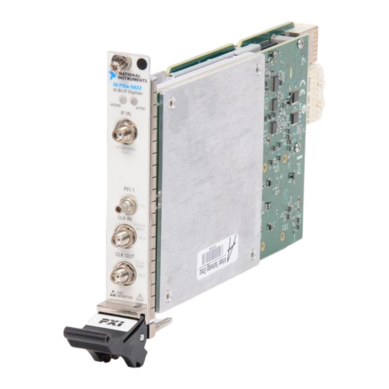
Chapter 2 Hardware Overview Connecting Signals Figure 2-2 shows the NI 562x front panel, which contains three connectors: two SMA connectors and an SMB connector. One of the SMA connectors, INPUT, is for attaching the analog input signal you want to measure. The second SMA connector, REF CLK IN, is a 50 Ω, 10 MHz, AC-coupled reference input. -
Page 17: Conditioning The Signal-Impedance, Dither, Gain, And Ac Coupling
64 MS/s. If you request a rate less than 64 MS/s, the timing engine of the NI 562x stores only one sample in a group of n samples, effectively reducing the sample rate to 64/n MS/s. © National Instruments Corporation NI PXI-562x User Manual... -
Page 18: Incorporating The Ddc
Chapter 2 Hardware Overview Incorporating the DDC Optionally, you can route the data through the DDC before storing it in onboard memory. The DDC is a digital signal processing (DSP) chip, the Intersil HSP50214B. The first stage uses a digital quadrature mixer that shifts a signal to baseband from any frequency within the range of the digitizer. -
Page 19: Block Diagram
The PLL uses a phase detector to synchronize the acquisition clock to either a 10 MHz reference clock supplied through REF CLK IN or to the CLK 10 signal from the PXI backplane. You can also leave the acquisition clock in © National Instruments Corporation NI PXI-562x User Manual... -
Page 20: Other Features
Chapter 2 Hardware Overview a free-running state, in which the acquisition clock is not synchronized to any external reference. The voltage controlled crystal oscillator (VCXO) is a 64 MHz clock. The trigger and clock routing area directs clock signals and triggers. The TIO is the timing engine used for the NI 562x. -
Page 21: Triggering
Although the NI 562x is factory calibrated, it needs periodic calibration to verify that it is still within the specified accuracy. For more information on calibration, contact NI or visit the NI Web site at ni.com/support/calibrat © National Instruments Corporation NI PXI-562x User Manual... -
Page 22: Synchronizing Multiple Pxi Devices
Chapter 2 Hardware Overview Synchronizing Multiple PXI Devices The NI 562x uses a PLL to synchronize the 64 MHz sample clock to a 10 MHz reference clock. You can either supply the reference clock through the SMA connector (REF CLK IN) on the front panel or use the system reference clock on the PXI backplane. -
Page 23: Technical Support And Professional Services
Technical Support and Professional Services Visit the following sections of the National Instruments Web site at for technical support and professional services: ni.com • Support—Online technical support resources include the following: – Self-Help Resources—For immediate answers and solutions, visit our extensive library of technical support resources available in English, Japanese, and Spanish at . -
Page 24: Glossary
µ- micro- milli- –3 kilo- mega- giga- Symbols percent positive of, or plus – negative of, or minus ° degree ± plus or minus Ω < less than amperes analog-to-digital alternating current © National Instruments Corporation NI PXI-562x User Manual... - Page 25 Typically, a bus is the expansion vehicle to which I/O or other devices are connected. An example of the PC bus is the PCI bus. Celsius CMOS complementary metal oxide semiconductor—a process used in making chips. NI PXI-562x User Manual © National Instruments Corporation...
- Page 26 DMA is the fastest method of transferring data to/from computer memory. double insulated a device that contains the necessary insulating structures to provide electric shock protection without the requirement of a safety ground connection © National Instruments Corporation NI PXI-562x User Manual...
- Page 27 NI PXI-562x User Manual © National Instruments Corporation...
- Page 28 MXI Interface to Everything—a custom ASIC designed by NI that implements the PCI bus interface. The MITE supports bus mastering for high-speed data transfers over the PCI bus. multiple-record multiple, distinct chunks (or records) of data acquisition © National Instruments Corporation NI PXI-562x User Manual...
- Page 29 PCI eXtensions for Instrumentation—PXI is an open specification that builds on the CompactPCI specification by adding instrumentation-specific features NI PXI-562x User Manual © National Instruments Corporation...
- Page 30 4-wire resistance the sense measures the voltage across the resistor being excited by the excitation current settling time the amount of time required for a voltage to reach its final value within specified limits © National Instruments Corporation NI PXI-562x User Manual...
- Page 31 NI PXI-562x User Manual © National Instruments Corporation...
- Page 32 © National Instruments Corporation NI PXI-562x User Manual...
-
Page 33: Index
AC coupling, 2-3 example code, A-1 dither, 2-3 gain, 2-3 input impedance, 2-3 connecting signals, 2-2 frequently asked questions, A-1 contacting National Instruments, A-1 front panel (figure), 2-2 conventions used in the manual, ix coupling, 2-3 customer education, A-1 gain, 2-3... - Page 34 2-6 safety information, 1-4 timing diagram (figure), 2-7 signal conditioning coupling, 2-3 dither, 2-3 gain, 2-3 National Instruments input impedance, 2-3 customer education, A-1 signal path from NI PXI-562x to host professional services, A-1 computer, 2-1 system integration services, A-1...
- Page 35 TIO (timing engine), 2-6 training customer, A-1 trigger and clock routing area, 2-6 professional services, A-1 triggering technical support, A-1 digital trigger sources (figure), 2-7 worldwide technical support, A-1 overview, 2-7 troubleshooting resources, A-1 © National Instruments Corporation NI PXI-562x User Manual...