Table of Contents
Advertisement
Quick Links
Advertisement
Table of Contents

Related Manuals for National Instruments NI 5731


Summary of Contents for National Instruments NI 5731
- Page 1 NI-5732...
-
Page 2: Table Of Contents
NI 5731/5732/5733/5734R User Guide and Specifications The NI 5731/5732/5733/5734 is a family of high-speed digitizer adapter modules designed to work in conjunction with your NI FlexRIO FPGA module. This document contains signal information and specifications for the NI 5731/5732/5733/5734R, which is composed of an NI FlexRIO FPGA module and the NI 5731/5732/5733/5734. -
Page 3: Electromagnetic Compatibility Guidelines
Caution To ensure the specified EMC performance, install the included snap-on ferrite bead (National Instruments part number 711856-01) on any cable attached to the AUX I/O connector in accordance with the instructions listed in the Appendix: Installing EMI Controls section. -
Page 4: How To Use Your Ni Flexrio Documentation Set
Other Useful Information on ni.com ni.com/ipnet Contains LabVIEW FPGA functions and intellectual property to share. ni.com/flexrio Contains product information and data sheets for NI FlexRIO devices. These documents are also available at ni.com/manuals © National Instruments Corporation NI 5731/5732/5733/5734R User Guide and Specifications... -
Page 5: Front Panel And Connector Pinouts
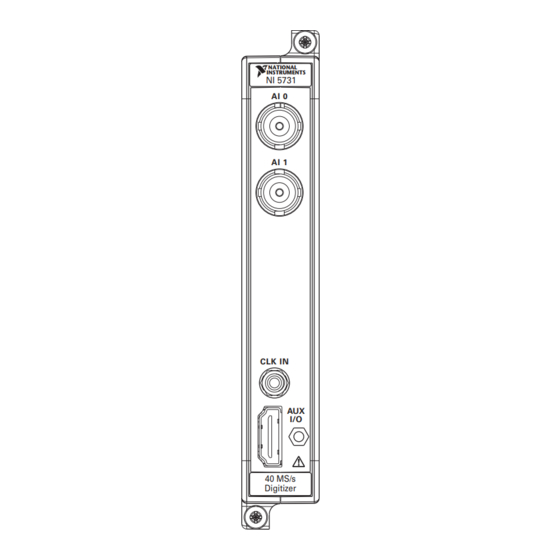
Front Panel and Connector Pinouts Front Panel Table 2 shows the front panel connector and signal descriptions for the NI 5731/5732/5733/5734. Refer to the Specifications section of this document for additional signal information. Table 2. NI 5731/5732/5733/5734 Front Panel Connectors... - Page 6 The AUX I/O connector accepts a standard, third-party HDMI cable, but the AUX I/O port is not an HDMI interface. Do not connect the AUX I/O port on the NI 5731/5732/5733/5734 into the HDMI port of another device. NI is not liable for any damage resulting from such signal connections.
-
Page 7: Block Diagram
Block Diagram Figure 3 shows the NI 5731/5732/5733/5734 block diagram and signal flow to and from the NI 5731/5732/5733/5734 component-level intellectual property (CLIP) by way of the adapter module and the corresponding CLIP in LabVIEW FPGA. NI 5731/5732/5733/5734 Adapter Module... -
Page 8: Ni 5731/5732/5733/5734 Component-Level Intellectual Property (Clip)
NI 5731/5732/5733/5734 Component-Level Intellectual Property (CLIP) The LabVIEW FPGA Module includes a feature for HDL IP integration called CLIP. NI FlexRIO devices support two types of CLIP: user-defined and socketed. • User-defined CLIP allows users to insert HDL IP into an FPGA target, enabling VHDL code to communicate directly with an FPGA VI. -
Page 9: Cables
Use any shielded 50 coaxial cable of less than 3 meters in length with a BNC plug end to connect • to the AI 0, AI 1, AI 2, and AI 3 connectors on the NI 5731/5732/5733/5734 front panel. Use any shielded 50 coaxial cable of less than 3 meters in length with an SMB plug end to •... -
Page 10: Clocking
NI 5734 Min = 50 MHz NI 5734 Max = 120 MHz Duty Cycle Stabilizer (DCS) enabled. DCS enabled is the default setting for all NI 5731/5732/5733/5734 CLIP items. You can disable the DCS by adjusting register 9 in the ADC. -
Page 11: Using Your Device With A Labview Fpga Example Vi
Complete the following steps to run an example that acquires a waveform on AI 0 of the NI 5731/5732/5733/5734. Connect one end of an BNC cable to AI 0 on the front panel of the NI 5731/5732/5733/5734 and the other end of the cable to your device under test (DUT). - Page 12 DMA transfers or result in other clock performance and timeout errors -50400 when acquiring data on the NI 5731. To ensure that the NI 5731 self-recovers from this error, the host and FPGA VIs must be able to trap these timeout errors and reinitialize the FPGA. The following two...
-
Page 13: Creating A Labview Project And Running A Vi On An Fpga Target
Right-click IO Module in the Project Explorer window and select Properties. Select the NI 573x from the IO Module list. The available CLIP for the NI 5731/5732/5733/5734 is displayed in the General category of the Component Level IP pane. If the information in the General category is dimmed, select the Enable IO Module checkbox. - Page 14 12. Wire the error out terminal of the Open FPGA VI Reference function to the error in control of the Read/Write Control function. 13. Configure the Read/Write Control function by clicking the terminal section labeled Unselected, and selecting IO Module/AI 0 Data N. © National Instruments Corporation NI 5731/5732/5733/5734R User Guide and Specifications...
- Page 15 18. Save the VI as 573xSampleAcq(Host).vi Running the Host VI Connect one end of an BNC cable to AI 0 on the front panel of the NI 5731/5732/5733/5734 and the other end of the cable to your DUT. Open the front panel of 573xSampleAcq(Host).vi...
-
Page 16: Specifications
Specifications This section lists the specifications of the NI FlexRIO adapter module (NI 5731/5732/5733/5734). Pair these specifications with the specifications listed in the NI FlexRIO FPGA Module Installation Guide and Specifications. For more information about safety and electromagnetic compatibility refer to the... - Page 17 –136.6 –140.6 0.5175 18.6 –141.6 –139.6 NI 5732 2.055 33.4 –136.5 –148.4 1.0275 18.3 –141.7 –147.6 0.51375 10.7 –146.4 –146.3 NI 5733/5734 2.085 26.9 –138.4 –148.4 1.0425 14.8 –143.6 –147.6 0.52125 –148.3 –146.3 NI 5731/5732/5733/5734R User Guide and Specifications ni.com...
- Page 18 –87.1 dBc –87.1 dBc –84.1 dBc NI 5732 9.7 MHz –83.9 dBc –87.7 dBc –89.5 dBc NI 5733/5734 9.7 MHz –80.5 dBc –85.0 dBc –86.0 dBc Measured at –1 dBFS. © National Instruments Corporation NI 5731/5732/5733/5734R User Guide and Specifications...
- Page 19 –83 dB –80 dB Note For NI 5731/5732 devices only, the crosstalk is 4 dB worse than the values in Table 13 when you configure both channels to use filters. Table 14. NI 5734 only: AI Channel Crosstalk Receiver Channel (50 terminated) Channel Path (N ±...
- Page 20 Phase adjust DAC range NI 5731 ............406 ± 13 degrees NI 5732 ............427 ± 13 degrees NI 5733/5734 ..........429 ± 9 degrees Frequency adjust DAC range .........±160 ppm Data rate (IOModuleClock0) .........Sample rate © National Instruments Corporation NI 5731/5732/5733/5734R User Guide and Specifications...
- Page 21 Figure 8. AC-Coupled Low Frequency Response (Multiple Channels Overlaid) –1 –2 –3 –4 –5 –6 –7 NI 5731 NI 5732 NI 5733/5734 –8 Frequency ( MHz ) Figure 9. Filter Bypass Frequency Response (Multiple Channels Overlaid) NI 5731/5732/5733/5734R User Guide and Specifications ni.com...
- Page 22 Figure 10. Elliptic Filter Frequency Response (Multiple Channels Overlaid) –1 –2 –3 –4 –5 NI 5731 NI 5732 NI 5733/5734 –6 Frequency ( MHz ) Figure 11. Elliptic Filter Frequency Response: 0 to –6 dB (Multiple Channels Overlaid) © National Instruments Corporation NI 5731/5732/5733/5734R User Guide and Specifications...
- Page 23 Figure 12. Bessel Filter Frequency Response (Multiple Channels Overlaid) –1 –2 –3 –4 –5 NI 5731 NI 5732 NI 5733/5734 –6 Frequency ( MHz ) Figure 13. Bessel Filter Frequency Response: 0 to –6 dB (Multiple Channels Overlaid) NI 5731/5732/5733/5734R User Guide and Specifications ni.com...
- Page 24 NI 5731 Group Delay –2 Frequency ( MHz ) Figure 14. NI 5731 Elliptic Filter Group Delay (12 Channels Overlaid) –1 –2 –3 –4 –5 Frequency ( MHz ) Figure 15. NI 5731 Bessel Filter Group Delay (12 Channels Overlaid) ©...
- Page 25 Frequency ( MHz ) Figure 16. NI 5732 Elliptic Filter Group Delay (12 Channels Overlaid) –1 –2 –3 –4 –5 Frequency ( MHz ) Figure 17. NI 5732 Bessel Filter Group Delay (12 Channels Overlaid) NI 5731/5732/5733/5734R User Guide and Specifications ni.com...
- Page 26 Figure 18. NI 5733/5734 Elliptic Filter Group Delay (44 Channels Overlaid) –1 –2 –3 –4 –5 –6 Frequency ( MHz ) Figure 19. NI 5733/5734 Bessel Filter Group Delay (44 Channels Overlaid) © National Instruments Corporation NI 5731/5732/5733/5734R User Guide and Specifications...
- Page 27 –100 –110 –120 –130 –140 –150 100k Frequency Offset (Hz) from 10 MHz Carrier Figure 20. NI 5731 AI Phase Noise (10 MHz Input, PLL Unlocked, Onboard Oscillator, 618 FS RMS Jitter) NI 5732 –100 –110 –120 –130 –140 –150 100k Frequency Offset (Hz) from 23.17 MHz Carrier...
- Page 28 Frequency Offset (Hz) from 40 MHz Carrier Figure 23. NI 5733/5734 AI Phase Noise (40 MHz Input, PLL Locked to PXI 10 MHz Reference Clock, Onboard Oscillator, 448 FS RMS Jitter) © National Instruments Corporation NI 5731/5732/5733/5734R User Guide and Specifications...
- Page 29 –20 –30 –40 –50 –60 –70 –80 –90 –100 –110 –120 Frequency (MHz) Figure 24. NI 5731 Gain at 0 dB; Elliptic, Bessel, or Filter Bypass; AC- or DC-coupled –10 –20 –30 –40 –50 –60 –70 –80 –90 –100 –110 –120...
- Page 30 –10 –20 –30 –40 –50 –60 –70 –80 –90 –100 –110 –120 Frequency (MHz) Figure 27. NI 5732 Gain at 12 dB; Elliptic, Bessel, or Filter Bypass; AC- or DC-coupled © National Instruments Corporation NI 5731/5732/5733/5734R User Guide and Specifications...
- Page 31 Figure 28. NI 5733/5734 Gain at 0 dB; Elliptic, Bessel, or Filter Bypass; AC- or DC-coupled –10 –20 –30 –40 –50 –60 –70 –80 –90 –100 –110 –120 Frequency (MHz) Figure 29. NI 5733/5734 Gain at 12 dB; Elliptic, Bessel, or Filter Bypass; AC- or DC-coupled NI 5731/5732/5733/5734R User Guide and Specifications ni.com...
- Page 32 –40 –50 –60 –70 –80 –90 –100 –110 Frequency (MHz) Figure 30. NI 5731 Gain at 0 dB: –1 dBFS at 4.9 MHz, –95 dBc SFDR, Bypass Filter, 100 Averages RMS –10 –20 –30 –40 –50 –60 –70 –80 –90 –100...
- Page 33 –40 –50 –60 –70 –80 –90 –100 –110 Frequency (MHz) Figure 32. NI 5731 Gain at 12 dB: –1 dBFS at 4.9 MHz, –93 dBc SFDR, Bypass Filter, 10 Averages RMS NI 5732 –10 –20 –30 –40 –50 –60 –70 –80...
- Page 34 –50 –60 –70 –80 –90 –100 –110 Frequency (MHz) Figure 35. NI 5732 Gain at 12 dB: –1 dBFS at 9.7 MHz, –94 dBc SFDR, Bypass Filter, 10 Averages RMS © National Instruments Corporation NI 5731/5732/5733/5734R User Guide and Specifications...
- Page 35 –20 –30 –40 –50 –60 –70 –80 –90 –100 –110 Frequency (MHz) Figure 37. NI 5733/5734 Gain at 12 dB: –1 dBFS at 20.1 MHz, –87 dBc SFDR, Bypass Filter, 100 Averages RMS NI 5731/5732/5733/5734R User Guide and Specifications ni.com...
- Page 36 –100 –110 Frequency (MHz) Figure 39. NI 5732 at 12 dB Gain and Filter Bypass: –83 dBc, f = 19.6 MHz (–7 dBFS), 20.8 MHz (–7 dBFS), 100 Average RMS © National Instruments Corporation NI 5731/5732/5733/5734R User Guide and Specifications...
- Page 37 ; clock distribution Oscillator type............VCXO Oscillator model.............Epson Toyocom TCO–2121U2 Frequency NI 5731 ............40 MHz ± 50 ppm NI 5732 ............80 MHz ± 100 ppm NI 5733/5734 ..........120 MHz ± 100 ppm Phase noise.............Refer to the Analog Input Total Phase Noise...
- Page 38 NI 5734 Min = 50 MHz NI 5734 Max = 120 MHz Duty Cycle Stabilizer (DCS) enabled. DCS enabled is the default setting for all NI 5731/5732/5733/5734 CLIP items. You can disable the DCS by adjusting register 9 in the ADC.
- Page 39 Physical Dimensions ............12.9 2.0 12.1 cm (5.1 0.8 4.7 in.) Weight NI 5731/5732/5733 ........313 g (11.0 oz) NI 5734 ............332 g (11.7 oz) Front panel connectors...........BNC, SMB, and HDMI NI 5731/5732/5733/5734R User Guide and Specifications ni.com...
- Page 40 For PXI/PXI Express chassis configurations that group NI FlexRIO adapter modules in three or more contiguous slots, National Instruments recommends limiting the ambient operating temperature to less than 50 C. © National Instruments Corporation NI 5731/5732/5733/5734R User Guide and Specifications...
- Page 41 For additional environmental information, refer to the NI and the Environment Web page at ni.com/ . This page contains the environmental regulations and directives with which NI environment complies, as well as other environmental information not included in this document. NI 5731/5732/5733/5734R User Guide and Specifications ni.com...
-
Page 42: Where To Go For Support
National Instruments corporate headquarters is located at 11500 North Mopac Expressway, Austin, Texas, 78759-3504. National Instruments also has offices located around the world to help address your support needs. For telephone support in the United States, create your service request at ni.com/ support and follow the calling instructions or dial 512 795 8248. -
Page 43: Appendix: Installing Emi Controls
For more installation information, refer to the NI FlexRIO FPGA Module Installation Guide and Specifications. Installing PXI EMC Filler Panels Complete the following instructions to install PXI EMC filler panels (National Instruments part number 778700-01) in your PXI chassis: Remove the captive screw covers. - Page 44 For patents covering National Instruments products/technology, refer to the appropriate location: Help»Patents in your software, the patents.txt file on your media, or the National Instruments Patent Notice at ni.com/patents. Refer to the Export Compliance Information at ni.com/legal/ export-compliance for the National Instruments global trade compliance policy.