National Instruments NI 5102 Getting Started Manual
High-speed digitizers
Hide thumbs
Also See for NI 5102:
- Getting started manual (68 pages) ,
- Getting started manual (68 pages)

Related Manuals for National Instruments NI 5102


Summary of Contents for National Instruments NI 5102
- Page 1 (217) 352-9330 | Click HERE Find the National Instruments PXI-5112 at our website:...
-
Page 2: Table Of Contents
NI-SCOPE instrument driver software. This document applies to the following digitizers: NI 5102, NI 5105, NI 5112, NI 5114, NI 5122, NI 5124, NI 5142, NI 5152, NI 5620, NI 5621, NI 5911, and NI 5922. -
Page 3: Conventions
NI 5114 Front Panels .................15 NI 5122/5124/5142/5922 Front Panels..........16 NI 5152 Front Panels .................18 Appendix B: Front Panels for Traditional NI-DAQ (Legacy) Devices..19 NI 5102 Front Panels .................19 NI 5112 Front Panels .................23 NI 5620/5621 Front Panels ..............24 NI 5911 Front Panel................25 Appendix C: Troubleshooting ..............26... -
Page 4: Verifying System Requirements
NI-SCOPE Readme, which is available on the NI-SCOPE CD. After you install NI-SCOPE, you can access the NI-SCOPE Note Readme file at Start»All Programs»National Instruments» NI-SCOPE»Documentation. 2. Unpacking NI high-speed digitizers are shipped in an antistatic bag to protect them from electrostatic discharge (ESD). -
Page 5: Verifying The Kit Contents
Note Measurement & Automation Explorer (MAX) under Traditional NI-DAQ (Legacy) Devices. SMC-based devices are based on the National Instruments Synchronization and Memory Core (SMC) architecture. SMC-based devices are configurable in MAX under NI-DAQmx Devices. For more information, refer to the NI High-Speed Digitizers Help. -
Page 6: Other Required Items
4. When the installer completes, a dialog box prompts you to Restart, Shut Down, or Restart Later. Select Restart. 5. If you are using a system running the LabVIEW Real-Time Module, download NI-SCOPE to the target using MAX. For more information, © National Instruments Corporation NI High-Speed Digitizers Getting Started Guide... -
Page 7: Installing The Hardware
refer to the Measurement & Automation Explorer Remote Systems Help by selecting Help»Help Topics»Remote Systems in MAX. 5. Installing the Hardware This section describes how to install hardware for PXI and PCI platforms. You must install the software before you install the Note hardware. -
Page 8: Pxi Express Modules
PXI Express slots. 1 PXI Express Chassis 4 NI PXI Express Module 2 Ejector Handle 5 Chassis Slot Markings 3 Screws Figure 2. PXI Express Module Installation © National Instruments Corporation NI High-Speed Digitizers Getting Started Guide... -
Page 9: Pci Devices
PCI Devices To install a PCI device, complete the following steps: 1. Power off and unplug the PC. 2. Remove the PC cover. 3. Insert the device into an open PCI slot as shown in Figure 3. 1 NI PCI Device 2 PCI Slot 3 PC Figure 3. - Page 10 For SMC-based devices, spread-spectrum clocking varies the Note clock signal to spread the timing clock signal over a small frequency range. Disabling spread-spectrum clocking may affect the accuracy of device specifications. © National Instruments Corporation NI High-Speed Digitizers Getting Started Guide...
-
Page 11: Configuring And Testing In Max
6. Configuring and Testing in MAX When you configure your device in MAX, remember that all Note SMC-based devices are configured under NI-DAQmx, and are referred to in MAX as NI-DAQmx devices. However, after you configure these devices in MAX, you use NI-SCOPE to program them. - Page 12 ADE, or you can use the Scope SFP. However, only NI-DAQmx devices (SMC-based devices) can be self-calibrated using MAX. 7. Exit MAX when you have finished configuring and testing the digitizer. © National Instruments Corporation NI High-Speed Digitizers Getting Started Guide...
-
Page 13: Programming The Digitizer
NI-SCOPE instrument driver in your application. You can also run the NI-SCOPE examples to demonstrate the functionality of the digitizer. Acquiring Data Interactively Launch the Scope SFP from Start»All Programs»National Instruments» NI-SCOPE»NI-SCOPE Soft Front Panel. The Scope SFP provides context-sensitive help for its controls. -
Page 14: Appendix A: Front Panels For Smc-Based Devices
Appendix A: Front Panels for SMC-Based Devices This appendix describes digitizer front panels and signal connections for SMC-based devices: NI 5105, NI 5114, NI 5122, NI 5124, NI 5142, NI 5152, and NI 5922. © National Instruments Corporation NI High-Speed Digitizers Getting Started Guide... -
Page 15: Ni 5105 Front Panels
NI 5105 Front Panels Figure 5 shows the NI PXI-5105 and NI PCI-5105 front panels. NI PXI-5105 NI PCI-5105 12-Bit 60 MS/s Digitizer CH 0 CH 0 CH 1 CH 1 CH 2 CH 2 CH 3 CH 3 CH 4 CH 4 CH 5 CH 5... -
Page 16: Ni 5114 Front Panels
Standard BNC Analog input connection; digitizes data and CH 1 female connector triggers acquisitions. TRIG Standard BNC External analog trigger connection; signals female connector on the TRIG connector cannot be digitized. © National Instruments Corporation NI High-Speed Digitizers Getting Started Guide... -
Page 17: Ni 5122/5124/5142/5922 Front Panels
Table 3. NI 5114 Front Panel Signal Connections (Continued) Connector Description Function CLK IN Standard SMB Input for an external reference or sample clock jack connector to the digitizer. AUX I/O 9-pin mini-circular Provides access to the multipurpose digital DIN connector timing and triggering lines, PFI 0, and PFI 1 (with optional cable). - Page 18 1 +5 V (Fused) 4 Reserved 7 Reserved 2 GND 5 Reserved 8 Reserved 3 Reserved 6 PFI 1 9 PFI 0 Figure 8. 9-Pin DIN Connector Pin Assignments for NI 5114/5122/5124/5142/5922 © National Instruments Corporation NI High-Speed Digitizers Getting Started Guide...
-
Page 19: Ni 5152 Front Panels
NI 5152 Front Panels Figure 9 shows the NI PXI-5152 and NI PCI-5152 front panels. NI PCI-5152 NI PXI-5152 8-bit 2GS/s Digitizer ACCESS ACTIVE CH 0 TRIG TRIG CH 1 PFI 0 PFI 1 PFI0 PFI1 Figure 9. NI 5152 Front Panels Table 5 describes the signal connections for the NI 5152. -
Page 20: Appendix B: Front Panels For Traditional Ni-Daq (Legacy) Devices
NI 5620/5621, and NI 5911. NI 5102 Front Panels The NI 5102 is available for PXI and PCI platforms. This section describes the front panels and signal connections for both types of NI 5102 digitizers. (NI PXI-5102) Figure 10 shows the NI PXI-5102 front panel. For the AUX connector pinout information, refer to Figure 11. - Page 21 Table 6 describes the signal connections for the NI PXI-5102. Table 6. NI PXI-5102 Front Panel Signal Connections Connector Description Function CH 0, Standard BNC Analog input connection; digitizes data and CH 1 female connector triggers acquisitions. TRIG Standard BNC External analog trigger connection;...
- Page 22 (NI PCI-5102) Figure 12 shows the NI PCI-5102 front panel. CH 0 CH 1 TRIG PFI 1 PFI 2 Figure 12. NI PCI-5102 Front Panel © National Instruments Corporation NI High-Speed Digitizers Getting Started Guide...
- Page 23 PFI 2 Standard SMB Multipurpose digital timing and triggering jack connector signal. When used as inputs, NI 5102 PFI lines can trigger an Note acquisition and/or allow an external sample clock connection. NI High-Speed Digitizers Getting Started Guide ni.com...
-
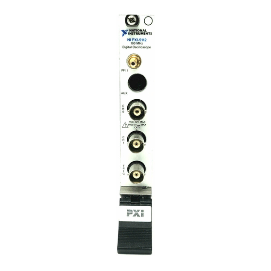
Page 24: Ni 5112 Front Panels
PFI 1 Standard SMB Multipurpose digital timing and triggering jack connector signal. 9-pin mini-circular Access to PFI 2 (with optional cable). For DIN connector pinout information, refer to Figure 11. © National Instruments Corporation NI High-Speed Digitizers Getting Started Guide... -
Page 25: Ni 5620/5621 Front Panels
NI 5620/5621 Front Panels Figure 14 shows the NI PXI-5620/5621 front panels. NI PXI-5620 NI PXI-5621 64 MS/s Digitizer 64 MS/s Digitizer INPUT INPUT +20 dBm MAX +20 dBm MAX ±2 VDC MAX ±3 VDC MAX REF CLK IN REF CLK IN +16 dBm MAX +20 dBm MAX ±10 VDC MAX... -
Page 26: Ni 5911 Front Panel
Standard SMB jack Multipurpose digital timing and triggering connector signal. PFI 2 (AUX) 9-pin mini-circular Access to PFI 2 (with optional cable). For DIN connector pinout information, refer to Figure 11. © National Instruments Corporation NI High-Speed Digitizers Getting Started Guide... -
Page 27: Appendix C: Troubleshooting
Appendix C: Troubleshooting Front Panel ACCESS LED on PXI Module is Off When PXI Chassis is On If the ACCESS LED on the digitizer is not lit after you power on the PXI chassis, a problem may exist with the PXI power rails, a hardware device, or the LED. -
Page 28: Device Failed The Self-Test
If the software optimization application is not installed on your system, use the MXI software CD or the National Instruments Driver CD included with your kit to install the software. After installation, you may need to reboot your computer before running the MXI Optimization Application. -
Page 29: Setting Up Smc-Based Devices For Synchronization
(MXI-4 and MXI-Express) Optimization is performed automatically by • the hardware. If you continue to have initialization or performance issues, refer to the MXI documentation at Start»All Programs»National Instruments MXI, or visit NI Technical Support at ni.com/support Setting Up SMC-Based Devices for Synchronization... -
Page 30: Appendix D: Where To Go For Support
Appendix D: Where to Go for Support The National Instruments Web site is your complete resource for technical support. At you have access to everything from ni.com/support troubleshooting and application development self-help resources to email and phone assistance from NI Application Engineers. - Page 31 National Instruments, NI, ni.com, and LabVIEW are trademarks of National Instruments Corporation. Refer to the Terms of Use section on ni.com/legal for more information about National Instruments trademarks. Other product and company names mentioned herein are trademarks or trade names of their respective companies. For patents covering National Instruments products, refer to the appropriate location: Help»Patents in your software, the patents.txt file on your CD, or ni.com/patents .