
Related Manuals for Sinclair SDV5 C1A Series


Summary of Contents for Sinclair SDV5 C1A Series
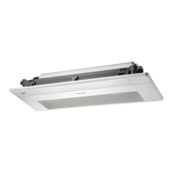
- Page 1 FULL DC INVERTER SYSTEMS INSTALLATION MANUAL INDOOR ONE-WAY CASSETTE UNITS SDV5-xxC1A C O M M E R C I A L A I R C O N D I T I O N E R S S D V 5...
-
Page 2: Important Note
Original instructions IMPORTANT NOTE: Read this manual carefully before installing or operating your new air conditioning unit. Make sure to save this manual for future reference. -
Page 3: Installation Precaution
2. ACCESSORIES Table.2-1 INSTALLATION PRECAUTION..............ACCESSORIES..................Name Q'ty APPEARANCE Function UNIT STRUCTURE INTRODUCTION............Indoor unit This manual (Please hand to user) INSTALLATION SPACE................installation manual INTDOOR UNIT INSTALLATION .............. For installing the suspender Installation paper plate and cutting the ceiling DRAINPIPE INSTALLATION.............. -
Page 4: Installation Space
3. Unit structure introduction 4. INSTALLATION SPACE Please avoid installing in the following places Unit mm A place with flammable gas or material. A saline place such as a seashore vicinity A place with sulphur gas. A place with oil gas, such as kitchen. A place with high-humidity air. - Page 5 Steel roof beam structure Model Unit mm Install the supporting angle steel. Hanging screw bolt Supporting angle steel Hanging bolts Fig.5-5 Please accord to the follow figure’s requirements to design the length of the suspender bolt. Hoisting the indoor unit take 18-36 as an example, operation method of 45-71are the same.
- Page 6 Install the panel component, and wiring (take 18-36 as an example, operation method of 45-71 are the same.) Two buckles on the panel component are used for assisting the panel installation, the installing method of the buckle as Fig.5.10 display. Panel component wiring: open the electric control panel, connect the wiring terminal of the control display box and the motor connecting terminal of the air leading bar as the figure...
-
Page 7: Drainpipe Installation
6. DRAINPIPE INSTALLATION Install the screw Before installation please check the connecting cable etween When connecting the pipe, please use the sealing material and panel and air conditioner whether has clamped, if clamped, pipe glove. the panel will be unfairness after fastening the screws and damage the wires. -
Page 8: Install The Connecting Pipe
Please according to the tube hardness to choose proper 7. INSTALL THE CONNECTING PIPE support density, do not appear obvious dropping and deformation situation. Dropping part will save the water and lead to poor drainage and abnormal noise. The connective length of indoor and outdoor piping and those height difference requirements. -
Page 9: Refrigerant Pipe Connection
Use frozen oil Fig.8-2 Fig.7-1 Table.8-1 Bend the pipe with thumb A(mm) Outside diameter Fig.7-2 12.4 12.0 Make the ends 15.8 15.4 straight Fig.7-3 19.0 18.6 Fasten the nut Locate The Pipe Put the connecting tubing at the proper position, wrench the Drill a hole in the wall (suitable just for the size of the wall conduit, nuts with hands then fasten it with a wrench. -
Page 10: Wiring Chart
9. WIRING CHART Air Purging Attaching wiring Use a vacuum pump, to vacuum from the gas side refrigerant adding mouth of the outdoor unit. The air conditioner should use separate power supply with rated voltage. Don’t use the refrigerant of the outdoor unit to do the vacuum. (A certain volume of refrigerant had been added into the The external power supply to the air conditioner should have outdoor unit in factory.) - Page 11 To wired To wired To outdoor/ indoor controller controller POWER INPUT units COMM. BUS COMM. BUS COMM. BUS P Q E X1 X2 E D2 D1 Wired controller Code Name XP4 XS4 P Q E X1 X2 Fan motor GM1-2 Swinging motor Display board Water drainage pump...
- Page 12 Outdoor power supply RCCB Wire slot Grounding line Indoor unit Grounding line Indoor power supply RCCB Signal wire for communicate indoor unit and outdoor unit Fig.9-4 Indoor Unit Wiring Guideline This wiring figure only for wiring method reference, the actual product may be different with this figure, please subject to the actual prodect! Ribbon which can be used repeatedly...
-
Page 13: Control Operation
10. CONTROL OPERATION Network address set Network address is set by communication of indoor and Horsepower set is no need to set separately. POWER_S CN20 SW1 SW7 ENC1 CN31 CN13 main control panel CN30 CN21 CN25 CN24 CN55 CN11 CN16 CN14 Fig.10-1 Base on different purposes to setting the switch cords on PC panel... - Page 14 Main board Code designation Guide for main control panel dial code ● 0 means cooling mode temperature ● 00 means shutting down the unit to compensation is 0°C (default) "stop cold air" at 15℃(default) ● 1 means cooling mode temperature ●...
-
Page 15: Test Operation
11. TEST OPERATION CAUTION The test operation must be carried out after the entire installation A protection feature prevents the air conditioner from being activated for has been completed. approximately 3 minutes when it is restarted immediately after shut off . Please confirm the following points before the test operation: The indoor unit and outdoor unit are installed properly. -
Page 16: Technical Support
SINCLAIR CORPORATION Ltd. 1-4 Argyll St. London W1F 7LD Great Britain www.sinclair-world.com This product was manufactured in China (Made in China). REPRESENTATIVE SINCLAIR Global Group s.r.o. Purkynova 45 612 00 Brno Czech Republic TECHNICAL SUPPORT SINCLAIR Global Group s.r.o. Purkynova 45...