
Related Manuals for Honeywell SILENT KNIGHT EVS Series


Summary of Contents for Honeywell SILENT KNIGHT EVS Series
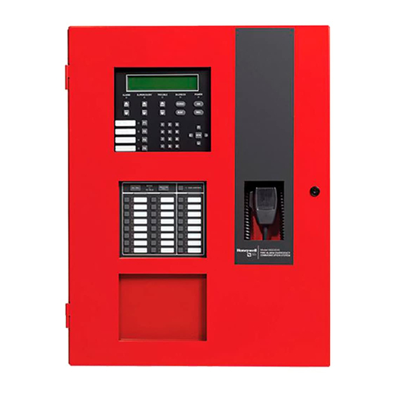
- Page 1 Emergency Voice System EVS Series Manual Document LS10062-001SK-E Rev: D 3/15/2022 ECN: 151062...
- Page 2 Fire Alarm & Emergency Communication System Limitations While a life safety system may lower insurance rates, it is not a substitute for life and property insurance! An automatic fire alarm system—typically made up of smoke IMPORTANT! Smoke detectors must be installed in the same room detectors, heat detectors, manual pull stations, audible warning as the control panel and in rooms used by the system for the devices, and a fire alarm control panel (FACP) with remote...
- Page 3 Flexput®, Honeywell®, JumpStart®, Silent Knight®, and SWIFT® are registered trademarks of Honeywell International Inc. Microsoft® and Windows® are registered trademarks of the Microsoft Corporation. Chrome™ and Google™ are trademarks of Google Inc. Firefox® is a registered trademark of The Mozilla Foundation.
- Page 4 Your suggestion for how to correct/improve documentation Send email messages to: FireSystems.TechPubs@honeywell.com Please note this email address is for documentation feedback only. If you have any technical issues, please contact Technical Services. This symbol (shown left) on the product(s) and / or accompanying documents means that used electrical and electronic products should not be mixed with general household waste.
-
Page 5: Table Of Contents
Table of Contents Section 1: Overview ................................7 1.1: Compatible EVS Series Equipment...................................7 1.2: ECS Features ........................................7 1.3: Terms Used in this Manual ....................................8 1.4: Related Documentation .....................................8 Section 2: Agency Listings, Approvals, and Requirements..................9 2.1: Federal Communications Commission (FCC)..............................9 2.2: Underwriters Laboratories (UL) ..................................9 2.2.1: Requirements for All Installations................................9 2.2.2: Requirements for Central Station Fire Alarm Systems ..........................9... - Page 6 Table of Contents 4.6.4: Wiring Specifications ...................................37 4.6.5: Speaker Wiring .....................................37 4.6.6: VBUS Wiring .......................................39 4.6.7: SBUS Wiring ......................................40 4.6.8: Setting the EVS-100W Backup Mode ..............................40 4.6.9: Test Switches ......................................41 4.6.10: Connecting AC Power ..................................41 4.6.11: Backup Battery for EVS-100W ................................41 4.6.12: Calculating Current Draw and Standby Battery ..........................42 4.7: Installing the EVS-100WBU ...................................42 4.7.1: EVS-100W Board Layout..................................43...
-
Page 7: Section 1: Overview
Section 1: Overview The Emergency Communication System Packages are a combination of the addressable fire alarm control panel and voice integration control all in one package. The general idea of the Emergency Communication System is to activate a message giving building occupants instruc- tions about an emergency event. -
Page 8: Terms Used In This Manual
UL standard 2572. FACP Fire Alarm Control Panel Local Operator's Console: The user interface for a Mass Notification System. In the Honeywell Silent Knight Series product line, this would be the interface provided by the 5820XL-EVS, 6820EVS, or EVS-LOC Mass Notification A way of protecting life by relaying specific event information to a building or site including voice and/or audible and visual signals. -
Page 9: Section 2: Agency Listings, Approvals, And Requirements
Section 2: Agency Listings, Approvals, and Requirements 2.1 Federal Communications Commission (FCC) The following information must be provided to the telephone company before the FACP can be connected to the phone lines: Manufacturer: Honeywell Silent Knight Model Number: 5820XL-EVS, 6820EVS FCC registration number:... -
Page 10: 3: Requirements For Local Protected Fire Alarm Systems
At least one UL listed supervised notification appliance must be used. 2.2.4 Requirements for Remote Station Protected Fire Alarm Systems Minimum system requirements are one Honeywell Silent Knight addressable initiating device and either a 5220, Keltron 3158, or the built- in Digital Alarm Communicator Transmitter (DACT). -
Page 11: Section 3: Installation
Section 3: Installation This section of the manual is intended to help you plan your tasks to complete the installation. Please read this section thoroughly, especially if you are installing a EVS Series control panel for the first time. 3.1 Environmental Specifications It is important to protect the EVS panel from water. - Page 12 Notes EVS Series Manual — P/N LS10062-001SK-E:D 3/15/2022...
-
Page 13: Section 4: Evs Device Installation
Section 4: EVS Device Installation 4.1 Connecting AC Power and Batteries Refer to the FACP Manual for proper AC and battery power connections. See Section 1.4 on page 8 for reference documentation. 4.2 Installing the EVS-VCM The EVS-VCM Voice Control Module is contained within the Silent Knight Series EVS panel enclosure. It provides a supervised micro- phone for live communication and an interface for the Emergency Voice System. -
Page 14: 2: Installing The Evs-Vcm
EVS Device Installation Installing the EVS-VCM 4.2.2 Installing the EVS-VCM Open the cabinet door and the dead front panel. Remove AC power and disconnect the backup batteries from the main control panel. Align the EVS-VCM over the mounting studs in the middle section of the dead front panel and secure with the six supplied nuts with lockwashers. -
Page 15: 4: Installing And Connecting The Evs-Sw24 To The Evs-Vcm
Installing the EVS-VCM EVS Device Installation 4.2.4 Installing and Connecting the EVS-SW24 to the EVS-VCM The EVS-SW24 adds 24 switches to the 5820XL-EVS and 6820EVS control panels for a total of 40 (with the 16 non-EVS switches on the EVS-VCM). Follow these steps to install and connect the EVS-SW24: Open the cabinet door and dead front panel. -
Page 16: Installing The Evs-50W
EVS Device Installation Installing the EVS-50W Insert microphone cord through hole at the bottom of the dead front panel. Figure 4.7 Microphone Cord Inserted Through Dead Front Panel Hole Attach strain relief clip to microphone cord. The strain relief clip should have about 2.75” of microphone cord through it. 2.75”... -
Page 17: 1: Evs-50W Board Layout
Installing the EVS-50W EVS Device Installation 4.3.1 -50W Board Layout Figure 4.9 shows the location of terminals, DIP switches, and expander connection, used in the installation of the EVS-50W. VBUS SBUS – – – SBUS SBUS ID DIP Switch Audio Expander CIRCUIT 4 CIRCUIT 3... -
Page 18: 3: Mounting The Evs-50Wbd Board Only
EVS Device Installation Installing the EVS-50W Install remaining fasteners and tighten. 14.5” 11” mounting key holes 24.75” bottom mounting holes Figure 4.10 Amplifier Cabinet Flush-Mount Dimensions and Mounting Hole Locations 4.3.3 Mounting the EVS-50WBD Board Only NOTE: Installation and wiring of this device must be done in accordance with NFPA 72 and local ordinance Ensure AC and DC power have been removed from the panel. -
Page 19: 4: Wiring Specifications
Installing the EVS-50W EVS Device Installation Restore AC power and reconnect the backup batteries. – – – SBUS mounting screws mounting screws CIR CUIT 4 CIRCUIT 3 CIRCUIT 2 CIRCUIT 1 – – – – – – – – Figure 4.11 EVS-50WBD In Enclosure 4.3.4 Wiring Specifications All wiring and devices installed in the system must meet the standards described in National Electrical Code (NFPA 70), NFPA Standard 72, and Life Safety Code (NFPA 101). -
Page 20: 5: Speaker Wiring
EVS Device Installation Installing the EVS-50W High frequency noise, such as that produced by the inductive 2 reactance of a speaker or bell, can also be reduced by running the wire through ferrite beads or by wrapping it around a ferrite toroid core. Figure 4.12 provides an example. audio circuits VBUS SBUS... -
Page 21: 6: Vbus Wiring
Installing the EVS-50W EVS Device Installation Class B Speaker Configuration Figure 4.13 illustrates how to wire speakers to the control panel using Class B supervision. C IR C U IT 4 C IR C U IT 3 C IR C U IT 2 C IR C U IT 1 –... -
Page 22: 7: Sbus Wiring
EVS Device Installation Installing the EVS-50W Connect the VBUS from the EVS-VCM to the EVS-50W amplifiers as shown in Figure 4.15. EVS-VCM VBUS connections 3 Vrms, 5mA max. supervised, power-limited Class B to next EVS-50W – – – – – –... - Page 23 Installing the EVS-50W EVS Device Installation Mount the transformer onto the threaded cabinet transformer mounting studs using the supplied locking hex nuts as shown in Figure 4.17. – – – SBUS C IR C U IT 4 C IR C U IT 3 C IR C U IT 2 C IR C U IT 1 –...
-
Page 24: 9: Backup Battery For Evs-50W
EVS Device Installation Installing the EVS-INT50W 4.3.9 Backup Battery for EVS-50W The following steps explain how to connect the batteries (refer to Figure 4.19): Connect the black wire of the battery harness to the (-) side of the battery #2. Connect the jumper wire provided form the positive (+) side of battery #2 to the negative side of battery #1. -
Page 25: 1: Board Layout & Mounting
Installing the EVS-INT50W EVS Device Installation 4.4.1 Board Layout & Mounting VBUS SBUS DIP switch mounting holes power input OUT1 Figure 4.20 EVS-INT50W Board Layout Mounting the EVS-INT50W Remove AC power and disconnect the backup batteries from the main control panel. To mount the EVS-INT50W inside the FACP cabinet below the main board, align the board with the mounting holes and secure the board to the enclosure with the eight supplied screws. -
Page 26: 4: Setting The Device Address
EVS Device Installation Installing the EVS-INT50W Connect the VBUS from the EVS-VCM to the EVS-INT50W amplifiers as shown in Figure 4.22 EVS-VCM AUDIO VBUS VBUS CMD2 COMMON CMD1 supervised, power-limited, Class B EVS-INT50W EVS-INT50W to next EVS-INT50W or EOL resistor Figure 4.22 VBUS Wiring for EVS-VCM to EVS-INT50W 4.4.4 Setting the Device Address Use the onboard DIP switches to select an ID number for the EVS-INT50W. -
Page 27: Installing The Evs-125W
Installing the EVS-125W EVS Device Installation No. of Standby Alarm Device Current Per Device Devices Current Current Multiply line C (alarm current) and F: Total alarm AH Add lines E and G (AH = Ampere Hours): Total AH required Table 4.2 Current Draw Calculations 4.5 Installing the EVS-125W This section provides information on how to install the EVS-125W for use with EVS series products. -
Page 28: 2: Mounting The Evs-125W
EVS Device Installation Installing the EVS-125W 4.5.2 Mounting the EVS-125W The EVS-125W is equipped with a separate enclosure. Refer to Section 3.1 when selecting a mounting location for the EVS-125W. The panel should be accessible to main drop wiring runs. It should be mounted as close to the center of the building as possible and located within a secured area, but should be accessible for testing and service. - Page 29 Installing the EVS-125W EVS Device Installation Secure the supplied “L-shaped” bracket to the top mounting bracket on the EVS-125WBD with the two mounting screws. CIRCUIT 4 CIRCUIT 3 CIRCUIT 2 CIRCUIT 1 – – – – – – – – Figure 4.25 EVS-125WBD Mounting Bracket Align the mounting holes on the bracket with the enclosure.
-
Page 30: 4: Wiring Specifications
EVS Device Installation Installing the EVS-125W 4.5.4 Wiring Specifications All wiring and devices installed in the system must meet the standards described in National Electrical Code (NFPA 70), NFPA Standard 72, and Life Safety Code (NFPA 101). To avoid induced noise (transfer of electrical energy from one wire to another), keep input wiring isolated from high-current output and power wiring. - Page 31 Installing the EVS-125W EVS Device Installation Wiring Lengths Number Of Speakers Total Load Wire Distance in Feet @1/2 W @1 W Vrms Watts 18 AWG 16 AWG 14 AWG 12 AWG 25Vrms 3900 6200 9860 15680 25Vrms 2125 3380 5375 8540 25Vrms 1460...
-
Page 32: 6: Vbus Wiring
EVS Device Installation Installing the EVS-125W 4.5.6 VBUS Wiring The VBUS is an analog voice bus that carries the recorded voice messages from the EVS-VCM to the EVS-125W or the voice messages generated from a system microphone to the EVS-125W. The maximum resistance on the VBUS is 20Ω. Connect the VBUS from the EVS-VCM to the EVS-125W amplifiers as shown in Figure 4.30. -
Page 33: 8: Connecting Ac Power
Installing the EVS-125W EVS Device Installation 4.5.8 Connecting AC Power Connect the AC terminals to the power source as shown in Figure 4.32. It may be necessary for a professional electrician to make this con- nection. The AC terminals are rated as 120 VAC, 60Hz. Figure 4.32 AC Connection 4.5.9 Backup Battery for EVS-125W The following steps explain how to connect the batteries (refer to Figure 4.33):... -
Page 34: Installing The Evs-100W
EVS Device Installation Installing the EVS-100W Batteries larger than 18 AH will not fit in the main control cabinet, and must be housed in the RBB Accessory Battery Cabinet. The system supports a maximum of 35 AH batteries. No. of Standby Alarm Device... -
Page 35: 2: Mounting The Evs-100W
Installing the EVS-100W EVS Device Installation 4.6.2 Mounting the EVS-100W The EVS-100W is equipped with a separate enclosure. Refer to Section 3.1 when selecting a mounting location for the EVS-100W. The panel should be accessible to main drop wiring runs. It should be mounted as close to the center of the building as possible and located within a secured area, but should be accessible for testing and service. - Page 36 EVS Device Installation Installing the EVS-100W Secure the supplied “L-shaped” bracket to the top mounting bracket on the EVS-100WBD with the two mounting screws. See Figure 4.36. Figure 4.36 EVS-100WBD Mounting Bracket Align the mounting holes on the bracket with the enclosure. Secure the board to the enclosure.
-
Page 37: 4: Wiring Specifications
Installing the EVS-100W EVS Device Installation 4.6.4 Wiring Specifications All wiring and devices installed in the system must meet the standards described in National Electrical Code (NFPA 70), NFPA Standard 72, and Life Safety Code (NFPA 101). To avoid induced noise (transfer of electrical energy from one wire to another), keep input wiring isolated from high-current output and power wiring. - Page 38 EVS Device Installation Installing the EVS-100W Wiring Lengths Number Of Speakers Total Load Wire Distance in Feet @1/2 W @1 W Vrms Watts 18 AWG 16 AWG 14 AWG 12 AWG 25Vrms 3900 6200 9860 15680 70Vrms 25000 39700 63200 100520 25Vrms 2125...
-
Page 39: 6: Vbus Wiring
Installing the EVS-100W EVS Device Installation Class A Speaker Configuration for EVS-100W Figure 4.40 illustrates how to wire speakers to the control panel using Class A wiring. AUDIO CIRCUIT OUT AUDIO CIRCUIT OUT AUDIO CIRCUIT IN AUDIO CIRCUIT IN supervised, power-limited Figure 4.40 Class A Speaker Configuration 4.6.6 VBUS Wiring... -
Page 40: 7: Sbus Wiring
When the EVS-100W is connected to a 5820XL-EVS version 13 or prior, see Figure 4.44 below to set the amplifier mode. If using version 14 or later, the mode is set using HFSS (Honeywell Fire Software Suite) and the DIP switch mode selector is ignored. -
Page 41: 9: Test Switches
Installing the EVS-100W EVS Device Installation Position (default) Figure 4.44 DIP Switch Modes 4.6.9 Test Switches See Figure 4.34 on page 34 for the location of the Test slide switches. SW1 - AMP A Switch should be moved to the “ON” position for normal operation. Move this switch to the “Test” position to test backup amplifier. SW2 - AMP B Switch should be moved to the “ON”... -
Page 42: 12: Calculating Current Draw And Standby Battery
EVS Device Installation Installing the EVS-100WBU Connect the red wire from the battery harness to the positive (+) side of battery #1. Figure 4.46 Battery Connection to EVS-100W 4.6.12 Calculating Current Draw and Standby Battery This section helps determine the current draw and standby battery needs for your installation (18 AH maximum will fit in cabinet). Complete the remaining instructions in Table 4.6. -
Page 43: 1: Evs-100W Board Layout
Installing the EVS-100WBU EVS Device Installation 4.7.1 EVS-100W Board Layout Figure 4.47 shows the location of the EVS-100WBU on the EVS-100W board. EVS-100WBU Figure 4.47 EVS-100WBU Mounting Location 4.7.2 Installing the EVS-100WBU Follow these steps to install the EVS-100WBU. Ensure all power supplied to the EVS-100W is removed. Secure the four standoffs supplied with the EVS-100W to the board as shown in Figure 4.48. -
Page 44: Installing The Evs-Ce4
EVS Device Installation Installing the EVS-CE4 Using the four supplied screws, secure the EVS-100WBU to the standoffs. secure with screws install standoffs EVS-100WBU cable harness Figure 4.48 Mounting the EVS-100WBU 4.8 Installing the EVS-CE4 The EVS-CE4 adds four audio circuits to the EVS-50W and EVS-125W. The EVS-CE4 mounts inside the EVS-50W or EVS-125W cabinet. Follow these steps to install the EVS-CE4. -
Page 45: Installing The Evs-Rvm
Installing the EVS-RVM EVS Device Installation Secure the EVS-CE4 to the backbox using the four supplied screws as shown in Figure 4.49. secure with screws C IR CU IT 5 CIRC U IT 6 + O U T – + IN – + OU T –... - Page 46 EVS Device Installation Installing the EVS-RVM SBUS address DIP switch SBUS not used dead front panel mounting holes VBUS aux audio input microphone aux audio EVS-SW24 connector trigger connector Figure 4.51 Back View of EVS-RVM READY NON-ACTIVE ALL CALL ECS CONTROL CALL TO TALK EVS Control...
-
Page 47: 2: Wiring The Evs-Rvm
Installing the EVS-RVM EVS Device Installation 4.9.2 Wiring the EVS-RVM Refer to Figure 4.53 to properly connect the EVS-RVM to the FACP’s SBUS. EVS-RVM supervised, power-limited Class B FACP Figure 4.53 EVS-RVM SBUS Connections Connect the SBUS to the annunciator and EVS-RVM. See Figure 4.54. from previous SBUS device annunciator... -
Page 48: 3: Installing The Microphone
EVS Device Installation Installing the EVS-RVM EVS-VCM supervised, power-limited Class B EVS-RVM EVS-125W Figure 4.55 VBUS and EVS-125W Wiring for EVS-RVM using the EVS-VCM 4.9.3 Installing the Microphone To install the microphone follow these steps: Clip the microphone onto the microphone clip. Insert microphone cord through hole at the bottom of the dead front panel. -
Page 49: 4: To Remove The Evs-Rvm
Addressing SBUS Devices EVS Device Installation 4.9.4 To Remove the EVS-RVM To remove the EVS-RVM follow these steps: Remove AC power and disconnect batteries from the main control panel. Disconnect the SBUS connections from the SBUS terminals on the EVS-RVM. Refer to Figure 4.54. Disconnect any devices connected to the VBUS. -
Page 50: Panel Security
Panel Security Panel installation / maintenance security checklist System Description: _________________________________________________________________ System Location: ___________________________________________________________________ Installer: ___________________________________________________ Date: __________________ Complete the following cyber security tasks for each panel installation. Install the panel in a secure location considering both software and hardware vulnerabilities. Change the default password to a unique password. - Page 51 Manufacturer Warranties and Limitation of Liability Manufacturer Warranties. Subject to the limitations set forth herein, Manufacturer warrants that the Products manufactured by it in its Northford, Connecticut facility and sold by it to its authorized Distributors shall be free, under normal use and service, from defects in material and workmanship for a period of thirty six months (36) months from the date of manufacture (effective Jan.
- Page 52 Honeywell Silent Knight 12 Clintonville Road Northford, CT 06472-1610 203.484.7161 LS10062-001SK-E | D | 03-22 www.silentknight.com ©2022 Honeywell International Inc.