Table of Contents
Advertisement
Quick Links
Installation, Operation, and Maintenance
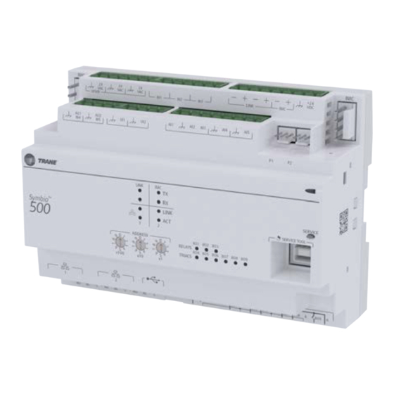
Symbio™ 500 Programmable
BACnet® Controller
for Variable-Air-Volume (VAV) Units
Only qualified personnel should install and service the equipment. The installation, starting up, and servicing of heating, ventilating, and air-conditioning equipment
can be hazardous and requires specific knowledge and training. Improperly installed, adjusted or altered equipment by an unqualified person could result in death or
serious injury. When working on the equipment, observe all precautions in the literature and on the tags, stickers, and labels that are attached to the equipment.
October 2022
SAFETY WARNING
BAS-SVX091A-EN
Advertisement
Table of Contents
Troubleshooting

Related Manuals for Trane Symbio 210


Summary of Contents for Trane Symbio 210
- Page 1 Installation, Operation, and Maintenance Symbio™ 500 Programmable BACnet® Controller for Variable-Air-Volume (VAV) Units SAFETY WARNING Only qualified personnel should install and service the equipment. The installation, starting up, and servicing of heating, ventilating, and air-conditioning equipment can be hazardous and requires specific knowledge and training. Improperly installed, adjusted or altered equipment by an unqualified person could result in death or serious injury.
- Page 2 Symbio 500 Dual Duct, BACnet over wired MS/TP, BACnet/IP over wired Ethernet, or wirelessly using optional module See Symbio 210 Programmable Variable Air Volume (VAV) Box Controller (BAS -SVX084) for more information. Note: LonTalk communications are not supported on Symbio 201/210e/400–B/500.
- Page 3 Non-Trane personnel should always follow local regulations. Copyright This document and the information in it are the property of Trane, and may not be used or reproduced in whole or in part without written permission. Trane reserves the right to revise this publication at any...
- Page 4 Introduction time, and to make changes to its content without obligation to notify any person of such revision or change. Trademarks All trademarks referenced in this document are the trademarks of their respective owners. BAS-SVX091A-EN...
-
Page 5: Table Of Contents
Table of Contents BACnet® Protocol ............. . 8 BACnet Testing Laboratory (BTL) Certification . - Page 6 Table of Contents Operation ..............29 LEDs.
- Page 7 Typical Trane Factory Wiring Diagrams ........
-
Page 8: Bacnet® Protocol
In addition, BACnet® defines a number of application services that are used to interact with objects in a BACnet® device. BACnet Testing Laboratory (BTL) Certification The Symbio 400–B/500 is BTL certified as a B-BC profile device. A complete list of Trane certified devices is available at www.bacnetinternational.org. BAS-SVX091A-EN... -
Page 9: Specifications And Dimensions
• UL60730-1 PAZX (Open Energy Management Equipment • UL94-5V Flammability • CE Marked. The European Union (EU) Declaration of Conformity is available from your local Trane® office. • UKCA Marked • FCC Part 15, Subpart B, Class B Limit •... -
Page 10: Shipping And Storage
Shipping and Storage Each VAV order ships with service literature. When unpacking, ensure that the literature is not lost or discarded with the packing material. Important: Visually inspect the individual components for obvious defects or damage. All components are thoroughly inspected before leaving the factory. Any claims for damage incurred during shipment must be filed with the carrier. -
Page 11: Symbio 500 Controller Features
Download: When applied with a Trane zone sensor module, that includes a thumbwheel setpoint or a LCD display, the Symbio 500 controller can easily be overridden to minimum and maximum flow. By simply turning the thumbwheel to * or increasing the... - Page 12 BACnet objects (data points) that can be read by and/or written to by other systems. Symbio 500 can communicate wirelessly to the BAS and zone sensors through the Trane Air-Fi Wireless system (BACnet/ Zigbee). This factory— or field-installed offering reduces project installation time and complexity and delivers reliable signal Trane Air-Fi Wireless strength through self-repairing mesh technology.
-
Page 13: Controller Comparisons
Symbio 500 and Tracer UC400 VAV Tracer VV550/VV551 VAV 4.2 Supports BACnet. Supports LonTalk. Supports Trane proprietary Comm4 or Comm3. Local CO2 sensor input is available. No local CO2 sensor input. Uses only a Local CO2 sensor input is available. communicated value. -
Page 14: Device Connections
Device Connections Table 4. Device connections Connection Quantity Types Range Notes Analog input (AI1 to Temperature 10k Ω – Type II, 10k Ω – Type III, AI1 to AI4 can be configured for timed override AI5) 2252 Ω – Type II, 20 kΩ – Type IV, capability. -
Page 15: Expansion Modules
Expansion Modules The Symbio 500 controller has 32 on-board points. The controller can be point-expanded by using expansion modules. The Symbio 500 can have an additional 110 points, for a total of 133 points Any combination of XM30, XM32, XM70, or XM90 Expansion Modules are supported. A maximum of two XM30, or XM32 modules (in aggregate) can be powered from the DC power of the IMC link. -
Page 16: Device Inputs/Outputs
Device Inputs/Outputs Below is a list of device inputs and outputs: • A twisted/shielded communication link • Zone sensor • Occupancy sensor (optional) • Discharge Air Temperature (DAT) and/or Supply Air Temperature (SAT) • • sensor • 24 Vac, Class II power In addition to the points used for the VAV application, the spare inputs and outputs on the Symbio 500 controller may be used for ancillary control and programmed using Tracer TU Tracer Graphical Programming 2 (TGP2). -
Page 17: Binary Inputs
Voltage output is 0 to 10 Vdc, 500 Ω minimum impedance. Current output is 4-20 mA, 500 Ω max. impedance. Also can output 100 Hz PWM signal for control of a Trane fan-powered ECM fan setpoint signal to the EC motor. -
Page 18: Wiring Installation
Wiring Installation Controller Pre-power Checkout WARNING Live Electrical Components! Failure to follow all electrical safety precautions when exposed to live electrical components could result in death or serious injury. When it is necessary to work with live electrical components, have a qualified licensed electrician or other individual who has been properly trained in handling live electrical components perform these tasks. -
Page 19: Guidelines
Wiring Installation WARNING Proper Field Wiring and Grounding Required! Failure to follow code could result in death or serious injury. All field wiring MUST be performed by qualified personnel. Improperly installed and grounded field wiring poses FIRE and ELECTROCUTION hazards. To avoid these hazards, you MUST follow requirements for field wiring installation and grounding as described in NEC and your local/state/national electrical codes. - Page 20 9.2 VA (Plus air damper draw) • actuator draw) • Total With a Trane F Series Box: 13.2 VA Total See device connected to DC supply for current draw. • Replace the control box cover after field wiring to prevent any electromagnetic interference.
-
Page 21: Bacnet® Ms/Tp Communication Link
Wired Ethernet is only an option on the Symbio 500 controller. Air-Fi Wireless BACnet® Communications Symbio 500 can communicate wirelessly to the Trane Tracer SC+ and zone sensors through the Trane Air-Fi Wireless system (BACnet/Zigbee). Wireless Air-Fi communications are the preferred method of communicating to the SC+. -
Page 22: Wiring Best Practices
SERVICE TOOL SERVICE TOOL SERVICE TOOL Symbio 500 Symbio 500 Symbio 500 Tracer SC+ Trane BACnet Zone Sensors Terminator Zone sensor communications jack wiring. Wiring Best Practices To ensure proper network communication, follow the recommended wiring and best practices below when installing communication wire: •... -
Page 23: Setting The Address
Wiring Installation Figure 3. Symbio 500 BACnet links Setting the Address The three (3) rotary address dials on the Symbio 500 serve one or two purposes depending upon the network: they are always used for the MAC Address, which is sometimes all or part of the BACnet Device ID. -
Page 24: Bacnet Networks With A Tracer Sc+ System Controller
Wiring Installation • It can be the same number as the MAC Address, determined by the rotary address dials on the Symbio 500 controller. For example, if the rotary address dials are set to 042, both the MAC Address and the BACnet Device ID are 042, OR •... -
Page 25: Power On Check
Wiring Installation • Ground one of the terminals on the controller to the enclosure (if the enclosure is adequately grounded) or to an alternate earth ground. Figure 5. Connecting 24 VAC transformer and ground A pigtail connection may be neces- sary between earth ground and/or enclosure ground if the device is 24 VAC... -
Page 26: Application Wiring
Wiring Installation Note: If the sequence completes as described, the controller is properly booted and ready for the application code. If the power LED flashes red, a fault condition exists. Application Wiring Zone Sensor Installation Zone Sensor Hard Wired Option Depending on the zone sensor options used, a maximum of seven (7) wires may be required to run from the Symbio 500 controller to the zone sensor. -
Page 27: Duct Temperature Sensor Wiring
Wiring Installation • All wiring must be in accordance with the NEC and local codes. • If local codes require enclosed conductors, install the zone sensor wires in the conduit. Important: Control wires and power conductors can never be near each other (except at 90 degrees). Do not run power wired through same conduit as signal wires. -
Page 28: Binary Wiring
Wiring Installation Binary Wiring Binary Input Wiring Each Symbio 500 controller provides three (3) binary inputs (BI1–BI3) with one being configured for occupancy with the standard VAV code. The binary inputs can be configured with the Tracer TU service tool for occupancy or other use. The input associates 0 Vac with open contacts and 24 Vac with closed contacts. -
Page 29: Operation
Operation LEDs LED Locations The Symbio 500 has the following LEDs located on the front (refer to the following illustration): • Marquee LED • Communication Status LEDs and IMC Status LEDs • Service Button LED • Binary Output Relay (3)/TRIAC (9) Status LEDs (only the Symbio 400) Figure 7. - Page 30 Operation Table 13. LED activities and troubleshooting tips Indication and Troubleshooting Tips LED Name Activities Notes Shows solid green when the unit is Indicates normal operation powered and no alarm exists. Shows blinking green during a device Indicates normal operation reset or firmware download.
-
Page 31: Marquee Led Status And Error Codes
Operation Table 13. LED activities and troubleshooting tips (continued) Indicates a corresponding binary If the user is currently powering the output has been commanded ON Symbio 400–B/500 from a USB port, the Led lights will turn ON. However, • Relay coil; indicates that a the binary outputs will not be command has been made to Shows solid yellow. - Page 32 Operation Table 14. Marquee LED status and error codes (continued) Message Description Action by User LED Blink Pattern Backup Retored Database backup has been restored. None- normal operation Updating Firmware Updating the firmware. None- normal operation Firmware Updated Firmware was updated. None- normal operation Updating Firmware Firmware is currently being updated.
- Page 33 Operation Table 14. Marquee LED status and error codes (continued) Message Description Action by User LED Blink Pattern Try upgrading the controller firmware Kernel Update Failure Failed to update the kernel. again Replace controller. Device Tree Failure Failed to update the kernel device tree. Not applicable for 210, 400–B, or 600.
-
Page 34: Controller Points And Parameters
You can use the Tracer TU service tool to view or adjust points and parameters in the Symbio 500 controller. It is a software application for monitoring, configuring, balancing, and testing Trane unit controllers, such as the Symbio 500 controller. -
Page 35: Analog, Binary, And Multi-State Screens
Controller Points and Parameters • Space Temperature (Active) Setpoint: The active (or actual) setpoint currently used by the Symbio 500 controller. Can be either Heating or Cooling depending on operating mode. • Space Temperature Setpoint BAS: Shows the setpoint being communicated to the VAV unit from a BAS system. -
Page 36: Setup Parameters Screen
Typically, it is not necessary to change this value. For Trane units, the nominal airflow and unit flow gain are based on unit size and are not adjustable. The default unit flow gain for generic VAV boxes is 1.0. - Page 37 Controller Points and Parameters Note: The flow offset is calculated only for two-point balancing, which requires reading both the maximum and minimum airflows during balancing. Two-point balancing ensures greater accuracy over the entire range of air valve operation. • Airflow Gain: The airflow gain is used to calibrate the value reported by the flow sensor so that the reported airflow matches the actual airflow.
-
Page 38: Commissioning Screen
Controller Points and Parameters Minimum Heat when local heat is on. This entry must be less than or equal to the entry for Airflow Setpoint Maximum Heat. Discharge Air Reset Limits The following parameters are used for Single Duct Units that are equipped with either modulating hot water reheat or SCR electric heat, which allows variable airflow when reheat is activated (for example, “dual maximums”... -
Page 39: Configuration Screen
Profile: This allows for selection between three operational programs. The three programs are Space Temperature, Ventilation Flow, and Flow Tracking. Equipment Options • Box Size: Used to select a Trane F-style box size or Generic Box. • Air Damper Opens: Chose between Clockwise and Counter-Clockwise damper rotation to open the damper. -
Page 40: Reheat Settings
Controller Points and Parameters • Parallel Fan Control: This entry will determine if a parallel fan is controlled based on zone temperature or on flow conditions. The entry field on this line will disappear if the unit does not have a parallel fan. -
Page 41: Setup Parameters Screen
Typically, it is not necessary to change this value. For Trane units, the nominal airflow and unit flow gain are based on unit size and are not adjustable. The default unit flow gain for generic VAV boxes is 1.0. - Page 42 Controller Points and Parameters • Space CO High Limit: The controller adjusts the ventilation setpoint based on the current CO2 concentration. When the concentration is greater than or equal to this high limit, the zone is most likely at design occupancy and the ventilation setpoint is set equal to Ventilation Setpoint Local. Flow Setpoints Setup •...
-
Page 43: Commissioning Screen
Controller Points and Parameters • Discharge Air Temperature Reset Maximum: This is the maximum discharge air temperature allowed when local heat (either modulating hot water or SCR electric) is on. Once the controller has increased airflow to Airflow Setpoint Reset Maximum Local Heat, reheat capacity is allowed to increase further, raising the discharge air temperature, but not above this maximum limit. -
Page 44: Configuration Screen
Profile: This allows for selection between three operational programs. The three programs are Space Temperature, Ventilation Flow, and Flow Tracking. Equipment Options • Box Size: Used to select a Trane F-style box size or Generic Box. • Air Damper Opens: Chose between Clockwise and Counter-Clockwise damper rotation to open the damper. -
Page 45: Calibration, Operation Modes, And Control
Calibration, Operation Modes, and Control Calibration The calibration sequence enables the controller to calibrate both, the air valve position and the water valve position. Calibration takes place if auto-calibration is enabled and either a power cycle or a transition from occupied to unoccupied has occurred. Note: Whether or not auto-calibration is enabled, the controller initiates calibration on a communicated application mode command. -
Page 46: Occupied Standby Mode
Calibration, Operation Modes, and Control A flow tracking controller runs the same as when it is occupied. When the controller is in the unoccupied mode and configured for flow tracking control, it runs the same as it does in occupied mode. Occupied Standby Mode Occupied standby mode is used to reduce the heating and cooling demands during the occupied hours when the space is unoccupied. -
Page 47: Occupied Standby Mode
Calibration, Operation Modes, and Control When the controller is in the unoccupied mode, and configured for space temperature control, the controller attempts to keep the space temperature between the active unoccupied heating setpoint and the active unoccupied cooling setpoint. When the controller is in the unoccupied mode and configured for ventilation flow control, it will not run in unoccupied mode. - Page 48 Calibration, Operation Modes, and Control In addition, the controller compares the active space temperature setpoint and the active space temperature and calculates the desired capacity need to bring the space temperature up or down to the space temperature setpoint. The controller positions the modulating air valve to deliver the required airflow based on cooling or heating capacity required.
- Page 49 Airflow Setpoint Minimum Local Heat. Refer to the equipment catalog for Trane F-Style VAV boxes for minimum airflow settings based on box inlet size and heating element kW.
- Page 50 When reheat is de-energized, the cooling Airflow Minimum Setpoint is enforced. The Trane VAV unit's SCR electric heater module takes a 0-to-10 Vdc control signal from AO2. Any signal less than 0.2 Vdc, and the heater is turned off. For a signal between 0.2 and 10 Vdc, the heater is on and modulated up to 100% capacity.
- Page 51 Calibration, Operation Modes, and Control Table 16. Local heat only with no fan present (continued) Configuration Method of Control Stage 1 Stage 2 Stage 3 Local Remote On/Off electric Not applicable Local thermostatic: Local thermostatic: Local thermostatic: (1 to 3 stages) •...
- Page 52 Calibration, Operation Modes, and Control Table 17. Local heat only with parallel fan present (continued) Configuration Method of Control Stage 1 Stage 2 Stage 3 Local Remote Parallel Fan Fan and On/Off electric Not applicable Parallel Fan Local thermostatic: Local thermostatic: Local thermostatic: (1 to 3 stages) •...
-
Page 53: Fan-Powered Units
Calibration, Operation Modes, and Control Refer to on/off electric heat for operation. The main difference with ON/OFF hot water heating is the control of a two position hot water valve instead of the contact energizing an electric heat strip. Refer to and . •... -
Page 54: Ventilation Flow Control (Vfc)
Calibration, Operation Modes, and Control Series Fan Operation During Calibration During calibration, the series fan is OFF for 10 seconds during calibration after the air valve closes all the way. It remains OFF after the 10 seconds expires if: • System mode (communicated application mode or communicated heat/cool mode) is OFF. - Page 55 Calibration, Operation Modes, and Control Occupancy Source Temperature Air Valve Control Reheat Control Mode Constant volume (if Electric VFC staged reheat valid, control communicated Occupied, Staged hot water VFC staged reheat ventilation setpoint; Occupied control if not valid, Standby, or configured Occupied VFC modulating...
- Page 56 Calibration, Operation Modes, and Control outdoor air temperature is more than 48°F (8.88°C) below the discharge air temperature setpoint, the controller cannot provide the requested control performance. The controller provides no cooling capacity. If the outdoor air temperature (OAT) is above the discharge air temperature setpoint, the discharge air temperature cannot be controlled and the discharge air temperature is equal to the OAT.
-
Page 57: Flow Tracking (Ftc)
Calibration, Operation Modes, and Control is invalid and the local discharge air temperature sensor has failed, freeze protection is active and the water valve is open. Unoccupied Ventilation Flow Control The controller closes the air valve and the local electric heat and hot water heat are disabled. The hot water valves OPEN, if needed for freeze protection. -
Page 58: Troubleshooting
Troubleshooting WARNING Live Electrical Components! Failure to follow all electrical safety precautions when exposed to live electrical components could result in death or serious injury. When it is necessary to work with live electrical components, have a qualified licensed electrician or other individual who has been properly trained in handling live electrical components perform these tasks. -
Page 59: Troubleshooting Procedures
Troubleshooting Table 18. Controller diagnostics (continued) Diagnostic Air Valve Reheat Freeze protection active (ventilation flow Closed control) Thumbwheel in * position (single star Minimum airflow Normal Normal position) Thumbwheel in ** position (double star Maximum airflow Normal Normal position) Normal Normal Normal Normal... -
Page 60: Controller Communication Loss
BACnet system (for example, 107, 120, and so on), whether with other Trane BACnet controls or controls from another vendor. This three-digit rotary switch setting is used as both the BACnet MAC address and the BACnet Device ID. -
Page 61: Wired Zone Sensor Failure
Troubleshooting voltage tests, refer to the BACnet MS-TP Wiring and Link Performance Best Practices and Troubleshooting Guide (BAS-SVX51). Wired Zone Sensor Failure WARNING Hazardous Service Procedures! Failure to follow all precautions in this manual and on the tags, stickers, and labels could result in death or serious injury. - Page 62 Troubleshooting Table 19. Zone sensor (continued) Thermostat Thumbwheel Temperature (oF) Sensor Resistance (k Ohms) Resistance (Ohms) 16.1 15.7 15.4 15.0 14.6 14.3 14.0 13.6 13.3 13.0 12.6 12.3 12.1 11.8 11.5 11.2 11.0 10.7 10.4 10.2 10.0 Thumbwheel resistance checks are made at terminal 2 and 3 on the zone sensor. Temperature sensor resistance is measured at terminal 1 and 2 of the zone sensor.
-
Page 63: Wired Zone Sensor Setpoint Failure
Troubleshooting Wired Zone Sensor Setpoint Failure WARNING Hazardous Service Procedures! Failure to follow all precautions in this manual and on the tags, stickers, and labels could result in death or serious injury. Technicians, in order to protect themselves from potential electrical, mechanical, and chemical hazards, MUST follow precautions in this manual and on the tags, stickers, and labels, as well as the following instructions: Unless specified otherwise, disconnect all electrical power including remote disconnect and discharge all energy storing devices such as capacitors... -
Page 64: Typical Trane Factory Wiring Diagrams
Typical Trane Factory Wiring Diagrams NOTICE A DIVISION OF AMERICAN STANDARD INC. ALL RIGHTS RESERVED AVIS AVISO WARNING AVERTISSEMENT ADVERTENCIA Symbio 500 BAS-SVX091A-EN... -
Page 65: Additional Resources
Additional Resources • Air-Fi Wireless System IOM (BAS-SVX40*-EN) • Air-Fi Network Design (BAS-SVX55*-EN) • Air Systems for the Tracer SC+ Application Guide (BAS-APG036*-EN) • BACnet/IP Wiring and Best Practices Application Guide (BAS-APG046*-EN) • BACnet MS-TP Wiring and Link Performance Best Practices and Troubleshooting Guide (BAS- SVX51*-EN) •... - Page 66 Notes BAS-SVX091A-EN...
- Page 67 Notes BAS-SVX091A-EN...
- Page 68 For more information, please visit trane. com or tranetechnologies.com. Trane has a policy of continuous product and product data improvements and reserves the right to change design and specifications without notice. We are committed to using environmentally conscious print practices.