Table of Contents
Advertisement
Quick Links
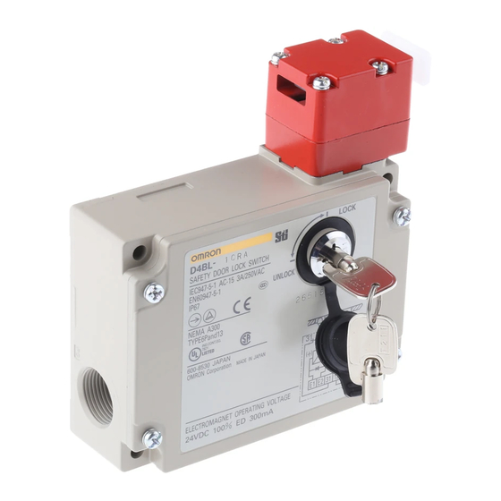
Guard Lock Safety-door Switch
D4BL
Release Protective Cover Locks Using
Controller Signals or Pushbutton Switches
after the Cutting Tool Stops Moving Due to
Inertia
• A mechanical lock is applied automatically when the Operation
Key is inserted. A high level of safety is achieved using a
mechanism where the lock is only released when voltage is
applied to the solenoid.
• Conforms to EN (TÜV) standards corresponding to the CE
marking.
• Approved by UL, CSA, BIA, SUVA and CCC standards.
• The Switch contact is opened by a direct opening mechanism
(NC contacts only) when the protective cover is opened. Direct
opening mechanism that is EN-approved is indicated by
the Switch.
• Auxiliary release key ensures easy maintenance and unlocks
the door in the case of a power failure.
• Tough aluminum die-cast body incorporating a switch box with
degree of protection satisfying IP67, UL, and CSA TYPE6P, 13.
• Equipped with a horizontal and vertical conduit opening.
• Models incorporating easy-to-see indicators for monitoring and
those using an adjustable Operation Key for a double door are
available.
• The mounting direction of the head can be changed to allow the
Operation Key to be inserted from four directions.
Note: Be sure to read the "Safety Precautions" on page A-78 and the
"Precautions for All Safety Door Switches" on page A-2.
Model Number Structure
■ Model Number Legend
Switch
D4BL -
-
1
2
3
4
1. Conduit Size (2-conduit)
1: PG13.5
2: G1/2
3: 1/2-14NPT
2. Built-in Switch (with Safety Switch and Lock Monitor
Switch Contacts)
C: 1NC/1NO (slow-action) + 1NC (slow-action)
D: 2NC (slow-action) + 1NC (slow-action)
3. Head Mounting Direction
R: Four mounting directions possible (right-side mounting at shipping)
Operation Key (Order Separately)
D4BL - K
1
1. Operation Key Type
1: Horizontal mounting
2: Vertical mounting
3: Adjustable mounting (Horizontal)
5
on
4. Door Lock and Release
(Auxiliary Release Key is Incorporated by All Models)
A: Mechanical lock/24-VDC solenoid release
B: Mechanical lock/110-VAC solenoid release
G: 24-VDC Solenoid lock/Mechanical release
5. Indicator
Blank: Without indicator
A:
10 to 115 VAC or VDC driving (with orange
and green LED indicator unit)
Guard Lock Safety-door Switch
D4BL
A-67
Advertisement
Table of Contents

Related Manuals for Omron D4BL


Summary of Contents for Omron D4BL
- Page 1 10 to 115 VAC or VDC driving (with orange and green LED indicator unit) 3. Head Mounting Direction R: Four mounting directions possible (right-side mounting at shipping) Operation Key (Order Separately) D4BL - K 1. Operation Key Type 1: Horizontal mounting 2: Vertical mounting 3: Adjustable mounting (Horizontal)
-
Page 2: Ordering Information
(Direct opening: approved) GS-ET-19 Mechanical lock: 9402293 Solenoid lock: 1998 20462-01 SUVA SUVA E6186/2.d UL508 E76675 CSA C22.2, No.14 LR45746 CQC (CCC) GB14048.5 2003010305073836 Note: Ask your OMRON representative for information on approved models. D4BL A-68 Guard Lock Safety-door Switch... - Page 3 Although the switch box is protected from dust, oil or water penetration, do not use the D4BL in places where dust, oil, water, or chemicals may enter through the key hole on the head, otherwise Switch damage or malfunctioning may occur.
- Page 4 Orange, green Connections ■ Contact Form (Diagrams Show State with Key Inserted and Lock Engaged) Model Contact Operating pattern Remarks D4BL-@C@@-@ 1NC/1NO+1NC Lock position Only NC contacts 11-12 and 31-32 have an approved direct opening mechanism. Stroke The terminals 11-12...
- Page 5 E1 (+) Solenoid Solenoid E2 ( ) E2 ( ) LED (orange) LED (orange) LED (green) LED (green) Auxiliary circuit Auxiliary circuit (Ground side) (Ground side) Safety circuit Safety circuit (monitor circuit) (monitor circuit) D4BL A-71 Guard Lock Safety-door Switch...
- Page 6 ■ Connection Example with OMRON’s G9SA Safety Relay Unit G9SA-321-T@ (24 VAC/VDC) + D4BL-@A-@, @B-@ (Mechanical Lock Type) Circuit Diagram (Manual Reset) Note: This example circuit is for Category 3. Lock release signal Safety Limit Switch with direct opening mechanism...
- Page 7 G9SA-301 (24 VAC/VDC) + D4BL-@G-@ (Solenoid Lock Type) Circuit Diagram (Auto-reset) Lock signal Note: 1. This example circuit is for Category 4. 2. The lock can be released at any time. Therefore, do not use a model with a solenoid lock in applications where the operator may be exposed to danger when the guard opens.
- Page 8 Nomenclature D4BL-@C@@-@ D4BL-@D@@-@ Operation Key Operation Key Lock plate Lock plate Auxiliary release key Rotating drum Auxiliary release key Rotating drum Lock monitor switch Lock monitor switch Operation plunger Solenoid Solenoid Operation plunger Seal ring (NBR) Seal ring (NBR) Auxiliary plunger...
- Page 9 Note: 1. All units are in millimeters unless otherwise indicated. 2. Unless otherwise specified, a tolerance of 0.4 mm applies to all dimensions. 3. There are fluctuations in the contact ON/OFF timing for 2NC contacts. Confirm performance before application. ■ Switches D4BL-@@@@-@ Four, M3.5 head clamping screws (116.5) 31.5...
-
Page 10: Horizontal Mounting
■ Operation Keys Horizontal Mounting Vertical Mounting D4BL-K1 D4BL-K2 53.7 78.7 5.3 x 7.3 long mounting hole 20 0.15 Long mounting hole 40.7 7.3 15 25.8 15.6 25.8 40 0.15 52.4 15.6 Two, 2.65R 5.3 11.9 7.5 11.8 11.8 4 dia. - Page 11 ■ With Operation Key Inserted Horizontal Mounting D4BL + D4BL-K1 Horizontal direction Vertical direction Operation Key insertion radius Operation Key insertion radius 1200 1000 53.5 min. 57 max. 53.5 min. 57 max. (20 0.15) (20 0.15) (12) (41) (41) (35)
-
Page 12: Safety Precautions
Switch. Electric shock may occur if the Switch is used without 2.75 N·m the cover attached. Connect a fuse in series with the D4BL in series to protect it from Two, M5 Operation Key mounting screw short-circuit damage. The value of the breaking current of the fuse must be calculated by multiplying the rated current by 150% to 200%. - Page 13 Switch Mounting Dimensions Four, M5 Incorrect 74 0.1 Greater than 0.3 100 0.1 The Operation Key for the D4BL is different from the one for the Operation Key Mounting Holes D4BS. • Horizontal Mounting Head Direction D4BL-K1 Two, M5 The head can be mounted in four directions. To remove the head, turn the head by 45 as shown in figures (A) and (B) below.
-
Page 14: Mounting The Cover
Cable Connection Example the indicator unit securely. 1. Connect the wires to the terminals in the order shown below for To ensure IP67, use OMRON’s SC-@M and Nippon Flex’s ABS- wiring efficiency. 08Pg13.5 and ABS-12 Pg13.5 Connectors. Recommended cable: UL2464-type cable that is AWG20 to AWG18 (0.5 to 1.0 mm... -
Page 15: Terms And Conditions Of Sale
Buyer indemnifies Omron against all related costs or expenses. rights of another party. 10. Force Majeure. Omron shall not be liable for any delay or failure in delivery 16. Property; Confidentiality. Any intellectual property in the Products is the exclu-... - Page 16 Cat. No. GC SAFETY-3 07/05 Specifications subject to change without notice Printed in USA...