Table of Contents
Advertisement
Quick Links
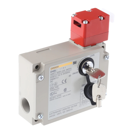
D4BL
Locking Safety-Door Switch
Protective Doors Are Locked Until
Machines Completely Stop Operating
The switch contact is opened by a positive
H
opening mechanism (NC contacts only).
Positive opening mechanism that is
EN-approved is indicated by
switch
Auxiliary release key ensures easy
H
maintenance and unlocks the door in the
case of a power failure
Tough aluminum die-cast Unit incorporating
H
a switch box with IP67 degree of protection
(EN60529, IEC529)
Standards and EC Directives:
H
Conforms to the following EC Directives:
Machinery Directive
Low Voltage Directive
EN1088
Approved Standards
H
Agency
Standard
TÜV Rheinland
EN60947-5-1
UL
UL508
CSA
CSA C22.2, No.14
BIA
GS-ET-19
SUVA
SUVA
on the
File No.
R9451050
(Positive opening:
approved)
E76675
LR45746
Mechanical lock:
9402293
Solenoid lock:
1998 20462-01
E6186/1.d
2
E
uC
Advertisement
Table of Contents

Related Manuals for Omron D4BL


Summary of Contents for Omron D4BL
- Page 1 D4BL Locking Safety-Door Switch Protective Doors Are Locked Until Machines Completely Stop Operating The switch contact is opened by a positive opening mechanism (NC contacts only). Positive opening mechanism that is EN-approved is indicated by on the switch Auxiliary release key ensures easy...
-
Page 2: Ordering Information
R: Mounting possible in 4 directions (with red and green LED indicator unit) (mounted in the right direction at time of delivery) Operation Key (Order Separately) D4BL - K 1. Operation Key Type Horizontal mounting Vertical mounting Adjustable mounting (Horizontal) -
Page 3: Specifications
D4BL J OPERATION KEY (ORDER SEPARATELY) Mounting type Part number Horizontal mounting D4BL-K1 Vertical mounting D4BL-K2 Adjustable mounting D4BL-K3 (Horizontal) Specifications J APPROVED STANDARD RATINGS TÜV (EN60947-5-1) Item Standard model Indicator model Utilization category AC-15 AC-15 Rated operating current (Ie) - Page 4 Operation Key insertion slot. 3. The life expectancy is for an ambient temperature of 5°C to 35°C and ambient humidity of 40% to 70%. For further conditions, consult your OMRON sales representative. Solenoid Coil Characteristics...
-
Page 5: Operation
D4BL Nomenclature D4BL-jCjj-j D4BL-jDjj-j Operation Key Operation Key Lock plate Lock plate Auxiliary release key Rotating drum Auxiliary release key Rotating drum Lock monitor switch Lock monitor switch Operation plunger Solenoid Operation plunger Solenoid Seal ring (NBR) Seal ring (NBR) -
Page 6: Internal Circuit
Two, 7 dia. the internal terminals (terminals 31 and 12, 23 and 24, and Two indicators 21 and 22) of the D4BL. 2. Each indicator unit must be connected in parallel with the contacts. When the contacts are open, the indicators will 26.8 53.2 57.2... - Page 7 D4BL J OPERATING MODE (Example of Electromagnetic Interlock System Operating Mode of D4BL-jCjA-A) Operating mode Door The protective door is The protective door is The protective door is The protective door is open. closed. closed and the machine is closed and the solenoid is operating.
- Page 8 D4BL Dimensions Unit: mm (inch) Note: A tolerance of ±0.4 mm applies to all dimensions unless otherwise specified. J SWITCHES D4BL-jjjj-j Four, M3.5 head clamping screws 31.5 116.5 37.5 Lock 34.2 protection Four, 5.3 dia. 123.5 mounting holes 74±0.1 Four, M4...
- Page 9 D4BL J WITH OPERATION KEY INSERTED Horizontal Mounting D4BL + D4BL-K1 Vertical direction Horizontal direction Operation Key insertion radius Operation Key insertion radius R ≧ 1000 (side view) R ≧ 1200 (side view) 53.5 min. 57 max. 53.5 min. 57 max.
-
Page 10: Installation
2 C 1 Note: Wire terminal 11 and terminal 22 on G9S to the PC output common. D4DN or D4BN Safety-door Lock Switch D4BL Guard Lock Safety-door Lock Switch with solenoid lock Reset switch KM1, KM2: J7K Magnet Contactor 3-phase motor... - Page 11 2 C 1 Note: Wire terminal 11 and terminal 22 on G9S to the PC output common. Safety Switch (D4D-j520N) D4BL Guard Lock Safety-door Lock Switch with mechanical lock Push-button switch for solenoid KM1, KM2: Magnet Contactor (LC1-D) 3-phase motor...
-
Page 12: Operating Environment
Operating Environment UNLOCK so that the lock will be released and the door can be Due to the wear and tear of the sealing of the D4BL, water and opened. some types of oil and chemical sprayed onto the D4BL may cause contact or insulation failures, current leakages, or fires. -
Page 13: Tightening Torque
Key and the during transportation. Be sure to remove the damper after D4BL as shown below. This may be due to the weight of the mounting the D4BL. door, vibration of the machine, or bouncing of the door against the rubber bumper. - Page 14 D4BL Switch and Operation Key Mounting Head Directions Mount the D4BL and Operation Key with four M5 screws with The head can be mounted in four directions. To remove the head, washers and tighten each screw to the specified torque.
-
Page 15: Mounting The Cover
CABLE/CONDUIT Switch body The following procedures are recommended for mounting and wiring the indicator unit securely. In order to ensure IP67, use OMRON’s SC-jM and Nippon Flex’s ABS-08Pg13.5 and ABS-12 Pg13.5 Connectors. Rotating lever (with protruding part) Recommended cable: UL2464-type cable that is 20 to 18 AWG Plunger (with groove) (0.5 to 1.0 mm... - Page 16 Insulation sheath edge Maintenance and Repairs Contact your OMRON representative for any repair or maintenance work on the D4BL. The D4BL must not be maintained or repaired by any unauthorized party. Using the D4BL Do not touch the solenoid because the solenoid radiates heat while power is being supplied.