
Related Manuals for Emerson Rosemount 3051N


Summary of Contents for Emerson Rosemount 3051N
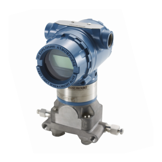
- Page 1 Reference Manual 00809-0100-4808, Rev CA June 2008 Rosemount 3051N Smart Pressure Transmitter for Nuclear Service www.rosemountnuclear.com...
- Page 3 Within the United States, contact Rosemount Nuclear Instruments, Inc. at 1-952-949-5210 for assistance. Outside of the United States, contact your local Emerson Process Management Sales Representative. The Rosemount logotype, and SMART FAMILY are registered trademarks of Rosemount Inc.
- Page 4 Chanhassen, MN 55317 IMPORTANT The Rosemount 3051N Pressure Transmitter is qualified for nuclear use per IEEE Std 344-1987 and IEEE Std 323-1983 (mild environment) as documented in Rosemount Report D2001019, and is supplied in accordance with 10CFR50 Appendix B and ISO 9001:2000 quality assurance programs.
- Page 5 Reference Manual 00809-0100-4808, Rev CA Rosemount 3051N June 2008 Revision Status Changes from June 2006 to June 2008 Page (Old) Page (New) Changes Cover, Cover, Document revision date change from June 2006 to June 2008, throughout throughout rev from BA to CA...
- Page 6 Reference Manual 00809-0100-4808, Rev CA Rosemount 3051N June 2008...
-
Page 7: Table Of Contents
Security Jumper Procedure ......2-3 Commissioning the Rosemount 3051N with a HART-Based Communicator . - Page 8 Digital-to-Analog Trim Using Other Scale....2-19 Compensating Rosemount 3051N Range 4 and 5 Differential Transmitters for Line Pressure ....2-20 SECTION 3 Overview .
- Page 9 Configuration Information ....... . . 5-11 Rosemount 3051N 4-20 mA/HART Output Smart Pressure Transmitters Typical Configuration Data Worksheet .
- Page 10 Reference Manual 00809-0100-4808, Rev CA Rosemount 3051N June 2008 Multifunction LED ........A-12 Touch Screen .
-
Page 11: Using This Manual
Appendix A: HART Communicator Gives an overview of the HART Communicator, defines its partial command menu tree for the Rosemount 3051N family, and provides a table of typical fast key sequences. A table of typical diagnostic messages is also included. - Page 12 Reference Manual Rosemount 3051N 00809-0100-4808, Rev CA June 2008...
-
Page 13: Overview
OVERVIEW This section contains information on commissioning and operating Rosemount 3051N Smart Pressure Transmitters. Tasks that should be performed on the bench prior to installation are explained in this section. When the HART Communicator is referenced, it refers to either the Rosemount 275 or Rosemount 375 as documented in Rosemount Report D2001019. -
Page 14: Failure Mode Alarm
To verify the transmitter alarm values, perform a loop test and set the transmitter output to the alarm value (see Table 2-1 and “Loop Test” in Section 2). TRANSMITTER There are three security methods with the Rosemount 3051N transmitter: SECURITY... -
Page 15: Security Jumper (Write Protect)
Reference Manual 00809-0100-4808, Rev CA Rosemount 3051N June 2008 Security Jumper: prevents all writes to transmitter configuration. Local Keys (Local Zero and Span) Software Lock Out: prevents changes to transmitter range points via local zero and span adjustment keys. With local keys security enabled, changes to configuration are possible via HART. -
Page 16: Commissioning The Rosemount 3051N With A Hart-Based Communicator
Alarm jumper not installed = High Alarm. COMMISSIONING THE Commissioning consists of testing the transmitter and verifying transmitter configuration data. You may commission Rosemount 3051N transmitters ROSEMOUNT 3051N either before or after installation. Commissioning the transmitter on the bench WITH A HART-BASED... -
Page 17: Setting The Loop To Manual
Reference Manual 00809-0100-4808, Rev CA Rosemount 3051N June 2008 To commission on the bench, connect the transmitter and the communicator as shown in Figure 2-3. Make sure the instruments in the loop are installed in accordance with intrinsically safe or nonincendive field wiring practices before connecting a communicator in an explosive atmosphere. -
Page 18: Wiring Diagrams (Field Hook-Up)
Reference Manual 00809-0100-4808, Rev CA Rosemount 3051N June 2008 Wiring Diagrams The following diagrams illustrate wiring loops for a field hook-up with a HART-based Communicator. (Field Hook-up) FIGURE 2-4. Field Hook-up (4–20 mA Transmitters). CAUTION ≥250Ω Do not use inductive-based transient protectors. -
Page 19: Review Configuration Data
Process Variables The process variables for the Rosemount 3051N provide the transmitter output, and are continuously updated. The process variable menu displays HART Comm. -
Page 20: Sensor Temperature
June 2008 NOTE Regardless of the range points, the Rosemount 3051N will measure and report all readings within the digital limits of the sensor. For example, if the 4 and 20 mA points are set to 0 and 10 in H... -
Page 21: Rerange
Reference Manual 00809-0100-4808, Rev CA Rosemount 3051N June 2008 FIGURE 2-5. Square Root Output Transition Point. Sq. Root Curve Transition Point Full Scale Output Full Scale (mA dc) Flow (%) Linear Section Sq. Root Curve Transition Point Slope=42 Slope=1 Rerange The Range Values command sets the 4 and 20 mA points (lower and upper range values). -
Page 22: Rerange With A Pressure Input Source And A Communicator
Reference Manual 00809-0100-4808, Rev CA Rosemount 3051N June 2008 NOTE If the transmitter security jumper is in the ON position, you will not be able to make adjustments to the zero and span. Refer to Figure 2-1 for the appropriate placement of the transmitter security jumper. - Page 23 Reference Manual 00809-0100-4808, Rev CA Rosemount 3051N June 2008 To rerange the transmitter using the span and zero buttons, perform the following procedure: Loosen the screw holding the label on top of the transmitter housing, and rotate the label to expose the zero and span buttons (see Figure 2-6).
-
Page 24: Damping
Reference Manual 00809-0100-4808, Rev CA Rosemount 3051N June 2008 Damping The process variable (PV) Damp command changes the response time of the transmitter to smooth variations in output readings caused by rapid changes HART Comm. 1, 3, 6 in input. Determine the appropriate damping setting based on the necessary response time, signal stability, and other requirements of the of loop dynamics of your system. -
Page 25: Transmitter Test
Reference Manual 00809-0100-4808, Rev CA Rosemount 3051N June 2008 Transmitter Test The transmitter Self Test command initiates a more extensive diagnostics routine than that performed continuously by the transmitter. The transmitter HART Comm. 1, 2, 1, 1 test routine can quickly identify potential electronics problems. If the transmitter test detects a problem, messages to indicate the source of the problem are displayed on the communicator screen. - Page 26 A HART Communicator is required for all sensor and output trim procedures. • Rosemount 3051N Range 4 and Range 5 transmitters require a special calibration procedure when used in differential pressure applications under high static line pressure (see “Compensating Rosemount 3051N Range 4 and 5 Differential Transmitters for Line Pressure”...
-
Page 27: Calibration Overview
• 4–20 mA Output Trim Using Other Scale (page 2-19) Figure 2-7 illustrates the Rosemount 3051N transmitter data flow. This data flow can be summarized in four major steps: A change in pressure is measured by a change in the sensor output (Sensor Signal). -
Page 28: Deciding Which Trim Procedure To Use
Reference Manual 00809-0100-4808, Rev CA Rosemount 3051N June 2008 FIGURE 2-7. Transmitter Data Flow with Calibration Options. Transmitter Ranged 0 to 100 inH Transmitter Electronics Module Microprocessor Sensor Digital PV Signal Sensor Input Pressure 20.00 mA Input Device Output Device... -
Page 29: Zero Trim
NOTE Do not perform a zero trim on Rosemount 3051N Absolute pressure transmitters. A zero trim is zero-based, and absolute pressure transmitters reference absolute zero. To correct mounting position effects on a Rosemount 3051N Absolute Pressure Transmitter, perform a low trim within the full sensor trim function. -
Page 30: Full Trim
Reference Manual 00809-0100-4808, Rev CA Rosemount 3051N June 2008 Full Trim To calibrate the sensor with a HART Communicator using the full trim function, perform the following procedure: HART Comm. 1, 2, 3, 3 Assemble and power the entire calibration system including a transmitter, HART Communicator, power supply, pressure input source, and readout device (see Figure 2-9). -
Page 31: Recall Factory Trim
Reference Manual 00809-0100-4808, Rev CA Rosemount 3051N June 2008 Recall Factory Trim The Recall Factory Trim commands allow the restoration of the as-shipped factory settings of the sensor trim and analog output trim. Recall Factory Trim— Resets the transmitter sensor trim to the as-shipped factory settings. The Recall Factory Trim—Sensor Trim command can be useful for recovering... -
Page 32: Compensating Rosemount 3051N Range 4 And 5 Differential Transmitters For Line Pressure
(P ) in these applications. Transmitters for Rosemount 3051N differential pressure transmitter ranges 0, 1, 2, and 3 do Line Pressure not require this procedure because the optimization occurs in the sensor. See “Static Pressure Effect”... - Page 33 0)(1200 psi) 1518 in H To complete a Rosemount 3051N full trim, enter the corrected values for low trim (LT) and high trim (HT). Refer to “Full Trim” on page 2-18. Enter the corrected input values for low trim and high trim through the communicator keypad after you apply the nominal value of pressure as the transmitter input.
- Page 34 Reference Manual 00809-0100-4808, Rev CA Rosemount 3051N June 2008 2-22...
-
Page 35: Overview
Environmental Considerations ..... page 3-14 OVERVIEW The information in this section covers installation considerations. Dimensional drawings illustrating the Rosemount 3051N and mounting brackets are included in this section. SAFETY MESSAGES Procedures and instructions in this section may require special precautions to ensure the safety of the personnel performing the operation. - Page 36 • Use only components supplied with the Rosemount 3051N or sold by Rosemount Nuclear Instruments Inc. as spare parts for the Rosemount 3051N. Improper assembly of manifold or mounting bracket to traditional flange can damage sensor module.
- Page 37 Reference Manual 00809-0100-4808, Rev CA Rosemount 3051N June 2008 FIGURE 3-1. Typical Installation Flowchart. START HERE Bench Calibration? Field Install Check Jumpers and Switches Configure (page 2-2) Verify (Section 2) Mount Transmitter (pages 3-4–3-14) Set Units Apply Pressure Wire Transmitter (pages 3-12–3-14)
-
Page 38: General Considerations
Install the enclosed pipe plug in unused conduit openings with a minimum of five threads engaged to comply with explosion proof requirements. MECHANICAL The following figures show dimensional drawings and installation examples of the Rosemount 3051N transmitters, including mounting brackets. CONSIDERATIONS NOTE For Rosemount 3051ND0 and 3051ND1, mount the transmitter solidly to prevent tilting. - Page 39 Keep drain/vent connections on the bottom for gas service and on the top for liquid service. NOTE The Rosemount 3051N transmitter incorporates two independent seals between the process connection and the conduit connection. FIGURE 3-2. Coplanar Flange...
- Page 40 Reference Manual 00809-0100-4808, Rev CA Rosemount 3051N June 2008 FIGURE 3-3. Rosemount 3051N Coplanar Flange Dimensional Drawing (Differential Pressure Transmitter Shown) 5 (127) -14 NPT Conduit Meter Label Connection Cover 4.3 (110) 4.1 (105) (two places) (optional) 0.75 (20) 0.75 (20)
- Page 41 Reference Manual 00809-0100-4808, Rev CA Rosemount 3051N June 2008 FIGURE 3-4. Traditional Flange Mounting Configurations with Optional Brackets for Panel Mounting OPTION CODE B2: OPTION CODE BS: TRADITIONAL FLANGE PANEL TRADITIONAL FLANGE MOUNTING BRACKET UNIVERSAL PANEL MOUNTING (PAINTED CARBON STEEL) BRACKET (STAINLESS STEEL) 9.5 (241)
- Page 42 Reference Manual 00809-0100-4808, Rev CA Rosemount 3051N June 2008 FIGURE 3-5. Traditional Flange (Option Code H2) Dimensional Drawing (127) -14 NPT Conduit Connection (Two Places) (110) 0.75 (20) Clearance for Cover Removal 0.75 (20) Clearance for Cover Removal Terminal connections...
-
Page 43: Mounting
(2,7 kg) without additional options. For complete weight information, including options, see “Physical Specifications” in Section 5. Optional mounting brackets available with the Rosemount 3051N allow mounting to a panel or wall. The B4 Bracket Option for use with the Coplanar flange is 316 SST and provided with 316 SST bolts. - Page 44 Reference Manual 00809-0100-4808, Rev CA Rosemount 3051N June 2008 NOTE In steam or other elevated temperature services, it is important that temperatures at the coplanar process flanges not exceed 250 °F (121 °C). In vacuum service, these temperature limits are reduced to 220 °F (104 °C).
- Page 45 Reference Manual 00809-0100-4808, Rev CA Rosemount 3051N June 2008 FIGURE 3-6. Typical Installation Examples to Illustrate Transmitter and Impulse Piping Locations. GAS OR LIQUID SERVICE GAS SERVICE STEAM SERVICE Flow Flow Flow Impulse Piping The piping between the process and the transmitter must accurately transfer the pressure to obtain accurate measurements.
-
Page 46: Process Connections
HART-based communicator. With 250 ohms of loop resistance, the transmitter will require a minimum of 16 volts to output 20 mA. If a single power supply is used to power more than one Rosemount 3051N transmitter, the power supply used, and circuitry common to the transmitters, should not have more than 20 ohms of impedance at 1200 Hz. -
Page 47: Wiring
5000 feet (1 500 meters). Do not use inductive-based transient protectors, including the Rosemount 470, as they can adversely affect the output of Rosemount 3051N 4–20 mA transmitters.The Rosemount 3051N includes the transient protection terminal block (T1) as standard. -
Page 48: Grounding The Transmitter Case
FIELD TERMINALS side of the electronics housing. This screw is identified by a ground symbol ( ), and is standard on all Rosemount 3051N transmitters. • External Ground Assembly: This assembly is included as standard with the transient protection terminal block (T1) included with the... -
Page 49: Overview
Reference Manual 00809-0100-4808, Rev CA Rosemount 3051N June 2008 Section 4 Troubleshooting Overview ........page 4-1 Safety Messages . -
Page 50: Returning Rosemount Products And Materials
The Rosemount 3051N must be returned to Rosemount Nuclear Instruments, Inc. (RNII) for repairs and/or failure analysis. Instructions for returning product follow. Any piece parts, if available, must be supplied by RNII to maintain the Rosemount 3051N qualification status. -
Page 51: Nuclear Specifications
Reference Manual 00809-0100-4808, Rev CA Rosemount 3051N June 2008 Section 5 Specifications and Reference Data Nuclear Specifications ......page 5-1 Performance Specifications . -
Page 52: Environmental
Reference Manual 00809-0100-4808, Rev CA Rosemount 3051N June 2008 Environmental Performance to normal operating limits as described in the “Performance Specifications” and “Functional Specifications” sections of this manual. Quality Assurance In accordance with 10CFR50 Appendix B, ISO 9001:2000 Program Nuclear Cleaning To <1 ppm chloride content... -
Page 53: Performance Specifications
Reference Manual 00809-0100-4808, Rev CA Rosemount 3051N June 2008 PERFORMANCE Based upon zero-based calibrations, reference conditions, 4–20mA analog output, and digital trim values equal to the span setpoints SPECIFICATIONS Reference Accuracy Includes hysteresis, terminal-based linearity, and repeatability Rosemount 3051ND Range Code Reference Accuracy ±... -
Page 54: Overpressure Effect
± 0.20% input reading (uncertainty after calibration correction for systematic effects) (1) Specification for Rosemount 3051N Range 0 is expressed in [% per 100 psi (689 KPa)] up to 750 psi (5 171 KPa) Less than ±0.005% of calibrated span per volt for RDF ≤ 10... -
Page 55: Functional Specifications
Reference Manual 00809-0100-4808, Rev CA Rosemount 3051N June 2008 FUNCTIONAL SPECIFICATIONS Service Liquid, gas, or vapor Output 4–20 mA, user-selectable for linear or square root output; digital signal based ® on HART protocol Power Supply Load Limitations Maximum loop resistance is determined by the voltage level of the external power supply, as described by: Max. -
Page 56: Span And Zero, Zero Elevation, And Suppression
Reference Manual 00809-0100-4808, Rev CA Rosemount 3051N June 2008 Span and Zero, Zero Zero and span values can be set anywhere within the range limits stated in Table 5-2 and Table 5-3, providing sensor limits are not exceeded. Elevation, and... -
Page 57: Maximum Working Pressure
Reference Manual 00809-0100-4808, Rev CA Rosemount 3051N June 2008 Figure 5-1. Typical Smart Transmitter Response Time Transmitter 4–20 mA Output vs. Time Pressure Released = Dead Time 20mA = Time Constant Response Time = 9.89mA 63.2% of Total Step Change... -
Page 58: Physical Specifications
Fill Fluid Silicone oil Flange Bolts Plated carbon steel, per ASTM A449, Type 1 (austenitic 316 SST per ASTM F593 for Rosemount 3051N Range Code 0) Electronics Housing Low-copper aluminum with polyester-polyurethane paint, or CF-3M (cast version of 316 SST) - Page 59 Reference Manual 00809-0100-4808, Rev CA Rosemount 3051N June 2008 Option Code Description Add: Stainless Steel Housing 3.1 lb (1.4 kg) Traditional Flange 2.4 lb (1.1 kg) LCD Meter for Aluminum Housing 0.5 lb (0.2 kg) LCD Meter for SST Housing 1.25 lb (0.6 kg)
-
Page 60: Ordering Information
Reference Manual 00809-0100-4808, Rev CA Rosemount 3051N June 2008 ORDERING INFORMATION Rosemount 3051N Differential, Gage, and Absolute Pressure Transmitters — = Not Applicable • = Applicable Rosemount Transmitter Type (Select One) 3051ND Differential Pressure Transmitter • — — 3051NG Gage Pressure Transmitter —... -
Page 61: Configuration Information
3051ND (1) All Rosemount 3051N transmitters are provided as standard with transient protection block (TI) and cleaning for < 1 PPM chloride. (2) Rosemount 3051ND0 is available only with Process Flange Code 0 (Alternate Flange H2), O-ring Code A, and stainless steel process flange bolting. - Page 62 Reference Manual 00809-0100-4808, Rev CA Rosemount 3051N June 2008 ROSEMOUNT 3051N 4-20 A/HART OUTPUT SMART PRESSURE TRANSMITTERS TYPICAL CONFIGURATION DATA WORKSHEET CONFIGURATION DATA SHEET Software Tag: |__|__|__|__|__|__|__|__| OUTPUT INFORMATION: (Software Selectable) 4 mA = ____________ 0★ Key to Symbols Upper Range Limit ★...
- Page 63 Reference Manual 00809-0100-4808, Rev CA Rosemount 3051N June 2008 HARDWARE SELECTABLE INFORMATION Alarm Option: High★ Transmitter Security Off★ SIGNAL SELECTION: (Software Selectable) 4–20 mA with simultaneous digital signal based on HART protocol★ Note: This is the only signal selection that has been evaluated for use in safety related applications.
- Page 64 Reference Manual 00809-0100-4808, Rev CA Rosemount 3051N June 2008 Figure 5-2. Rosemount 3051N Exploded View (with Coplanar Process Flange). Label Span and Zero Adjustments (Standard) Electronics Housing Terminal Block O-ring Cover Electronics Board Nameplate Sensor Module Housing Rotation Set Screw (180°...
- Page 65 Reference Manual 00809-0100-4808, Rev CA Rosemount 3051N June 2008 5-15...
- Page 66 Reference Manual 00809-0100-4808, Rev CA Rosemount 3051N June 2008 5-16...
-
Page 67: Overview
Transient Protection Terminal Block (T1) ... . . page 6-8 OVERVIEW The options available with the Rosemount 3051N can ease installation, improve the security of control systems, and simplify use. Included in this section is a description of LCD meter diagnostic messages. -
Page 68: Custom Meter Configuration
Reference Manual 00809-0100-4808, Rev CA Rosemount 3051N June 2008 The meter features a two-line display with five digits for reporting the process variable on the top line and six characters for displaying engineering units on the bottom line. The LCD meter can also display flow and level scales. The meter uses both lines to display diagnostic messages. -
Page 69: Installing The Meter
(when the kit is made available by Rosemount Nuclear Instruments, Inc.). To maintain the Rosemount 3051N qualification status, any piece parts for the Rosemount 3051N (if available) must be supplied by RNII. The meter kit includes: •... - Page 70 Reference Manual 00809-0100-4808, Rev CA Rosemount 3051N June 2008 4. Insert the interconnection header in the ten-pin socket exposed by removal of the jumpers. 5. Remove the two captive screws from the electronics module. To do so, loosen the screws to release the module, then pull out the screws until they are stopped by the captive thread inside of the circuit board standoffs.
-
Page 71: Diagnostic Messages
Reference Manual 00809-0100-4808, Rev CA Rosemount 3051N June 2008 FIGURE 6-2. Rosemount 3051N with Optional LCD Meter. Diagnostic Messages In addition to the output, the LCD meter displays abbreviated operation, error, and warning messages for troubleshooting the transmitter. Messages appear according to their priority, with normal operating messages appearing last. -
Page 72: Warnings
Reference Manual 00809-0100-4808, Rev CA Rosemount 3051N June 2008 Some non-volatile memory faults are user-addressable. Use a HART Communicator to diagnose the error and determine if it is repairable. Any error message that ends in “FACTORY” is not repairable. In cases of non user-addressable errors, you must replace the transmitter. -
Page 73: Operation
Security” in Section 2 for more information about the security jumper. MOUNTING BRACKETS Optional mounting brackets available with the Rosemount 3051N facilitate mounting to a panel. The standard bracket (option code B4) for use with the Coplanar flange is stainless steel with stainless steel bolts. Refer to Figure 3-2 in Section 3 for dimensions and mounting configurations. -
Page 74: Traditional Flange (H2)
Traditional Flange (H2) The traditional flange option converts the mounting configuration of the Rosemount 3051N to one similar to traditional style transmitters. This allows the Rosemount 3051N to replace traditional transmitters without changing existing manifolds, impulse piping, or bracket arrangements. The traditional flange also allows a higher process temperature at the process ports (300 °F... - Page 75 Reference Manual 00809-0100-4808, Rev CA Rosemount 3051N June 2008 FIGURE 6-4. Transient Protection Terminal Block (T1).
- Page 76 Reference Manual 00809-0100-4808, Rev CA Rosemount 3051N June 2008 6-10...
-
Page 77: Introduction
NOTE You may need to upgrade the software in your HART Communicator in order to take advantage of all features of the Rosemount 3051N. If you initiate communication with a Rosemount 3051N using a Communicator that has a previous version of the transmitter Device Descriptors (DDs), the communicator will display the following message: Notice: Upgrade software to access XMTR function. -
Page 78: Warnings
Reference Manual 00809-0100-4808, Rev CA Rosemount 3051N June 2008 Warnings Explosions can result in death or serious injury. • Do not remove the transmitter covers in explosive environments when the circuit is alive. • Before connecting a communicator in an explosive atmosphere, make sure the instruments in the loop are installed according to intrinsically safe or nonincendive field wiring practices. - Page 79 Reference Manual 00809-0100-4808, Rev CA Rosemount 3051N June 2008 FIGURE A-1. HART Communicator Typical Abbreviated Menu Tree for Rosemount 3051. Online 1 PROCESS 1 Pressure 1 Keypad Input Menu VARIABLE 2 Percent Range 2 Apply Values 1 DEVICE 3 Analog Output...
- Page 80 Reference Manual 00809-0100-4808, Rev CA Rosemount 3051N June 2008 Table A-1. Typical HART Fast Key Sequences for the Rosemount 3051 (partial listing). Function HART Fast Key Sequence Alarm and Saturation Levels 1, 4, 2, 7 Analog Output Alarm Type 1, 4, 3, 2, 4...
-
Page 81: Connections And Hardware
Reference Manual 00809-0100-4808, Rev CA Rosemount 3051N June 2008 CONNECTIONS AND The HART Communicator can interface with a transmitter from the control room, the instrument site, or any wiring termination point in the loop through HARDWARE the communicator connections as shown in Figure A-2 and Figure A-3. To communicate, connect the HART Communicator in parallel with the instrument or load resistor. - Page 82 Reference Manual 00809-0100-4808, Rev CA Rosemount 3051N June 2008 FIGURE A-4. Bench Hook-up (4–20 mA Transmitters). 24 V dc Supply ≥ 250Ω Current Meter FIGURE A-5. Field Hook-up (4–20 mA Transmitters). CAUTION: Do not use inductive-based transient protectors. ≥ 250Ω...
-
Page 83: Rosemount 275
Reference Manual 00809-0100-4808, Rev CA Rosemount 3051N June 2008 ROSEMOUNT 275 Communicator Keys The keys of the Rosemount 275 HART Communicator include action, function, alphanumeric, and shift keys. FIGURE A-6. Rosemount 275 HART Communicator. Function Keys Action Keys Alphanumeric Keys... -
Page 84: Alphanumeric And Shift Keys
Reference Manual 00809-0100-4808, Rev CA Rosemount 3051N June 2008 Hot Key Use this key to quickly access important, user-selectable options when connected to a HART-compatible device. Pressing the HOT KEY turns the HART Communicator on and displays the Hot Key Menu. See “Customizing the Hot Key Menu”... -
Page 85: Fast Key Sequences
Use Table A-1, an alphabetical listing of most on-line functions, to find the corresponding HART fast key sequences. These codes are applicable only to Rosemount 3051N transmitters and the HART Communicator. MENUS AND The HART Communicator is a menu driven system. Each screen provides a... - Page 86 Utility–The Utility option provides access to the contrast control for the HART Communicator LCD screen and to the autopoll setting used in multidrop applications. Note that although the Rosemount 3051N has multi-drop capability, which is a HART protocol feature, the Rosemount 3051N is not qualified/dedicated for use in multi-drop mode.
-
Page 87: Multifunction Led
Reference Manual 00809-0100-4808, Rev CA Rosemount 3051N June 2008 ROSEMOUNT 375 Communicator Keys The keys of the Rosemount 375 HART Communicator include navigation, function, alphanumeric, and tab keys. The keypad and touch screen have nearly total function redundancy. FIGURE A-9. Rosemount 375 HART Communicator. - Page 88 Reference Manual 00809-0100-4808, Rev CA Rosemount 3051N June 2008 Enter Key The enter ( ) key allows you to launch the focused item or to complete an editing action. It does not navigate you through a menu structure. For example, if you have the Cancel button in focus (highlighted) when you push the enter key, you will be choosing to cancel out of that particular window.
-
Page 89: Using The Soft Input Panel (Sip) Keyboard
Reference Manual 00809-0100-4808, Rev CA Rosemount 3051N June 2008 The touch screen should be contacted by blunt items only, preferably the stylus included with the Rosemount 375 Field Communicator. The use of sharp instruments, such as screwdrivers, can cause failure of the touch screen interface. Repair of the touch screen requires replacement of the entire Rosemount 375 Field Communicator display assembly, which is possible only at an authorized service center. -
Page 90: Fast Key Sequences
Reference Manual 00809-0100-4808, Rev CA Rosemount 3051N June 2008 Fast Key Sequences The Fast Key sequence is a sequence of numerical button presses, corresponding to the menu options that lead you to a given task. Use Table A-1, an alphabetical listing of most on-line functions, to find the corresponding HART fast key sequences. - Page 91 Reference Manual 00809-0100-4808, Rev CA Rosemount 3051N June 2008 Message Description Add item for ALL Asks the user whether the hot key item being added should be device types or only added for all device types or only for the type of device that is for this ONE device connected.
- Page 92 Reference Manual 00809-0100-4808, Rev CA Rosemount 3051N June 2008 Message Description Looking for a device Polling for multidropped devices at addresses 1–15. Local buttons Illegal pressure applied during zero or span operation. Repeat operator error ON the process after verifying the correct pressures.
- Page 93 LOSE data device. Upgrade 275 The communicator does not contain the most recent software to access Rosemount 3051N Device Descriptors (DDs). Select YES to XMTR function. communicate using the existing DDs. Select NO to abort Continue with old communication.
- Page 94 Reference Manual 00809-0100-4808, Rev CA Rosemount 3051N June 2008 Message Description Value out of range The user-entered value is either not within the range for the given type and size of variable or not within the min/max specified by the device.
- Page 95 Commissioning Functions performed with a HART-based communicator and the transmitter which test the transmitter, test the loop, and verify transmitter configuration data. See “Commissioning the Rosemount 3051N with a HART-Based Communicator” in Section 2 . Configuration Process of setting parameters that determine how the transmitter operates.
- Page 96 Communication between the host and the transmitters takes place digitally with the analog output of the transmitters deactivated. Note that although the Rosemount 3051N has multi-drop capability, which is a HART protocol feature, the Rosemount 3051N is not qualified/dedicated for use in multi-drop mode. Reranging Configuration function that changes the transmitter 4 and 20 mA settings.
- Page 97 Reference Manual 00809-0100-4808, Rev CA Rosemount 3051N June 2008 Index ..3-14 . . . 3-12 ....6-1 Access Requirements Electrical Considerations LCD Meter .
- Page 98 Reference Manual 00809-0100-4808, Rev CA Rosemount 3051N June 2008 ....2-2 Security Local Zero and Span Physical ..2-3 Removal Local Zero and Span Software .
- Page 100 Rosemount 3051N June 2008 The Emerson logo is a trade mark and service mark of Emerson Electric Co. Rosemount and the Rosemount logotype are registered trademarks of Rosemount Inc. PlantWeb is a mark of one of the Emerson Process Management companies.