Emerson Rosemount 3051 Manual
Pressure transmitter with 4-20 ma hart protocol
Hide thumbs
Also See for Rosemount 3051:
- Quick start manual ,
- Reference manual (222 pages) ,
- Manual (127 pages)

Related Manuals for Emerson Rosemount 3051


Summary of Contents for Emerson Rosemount 3051
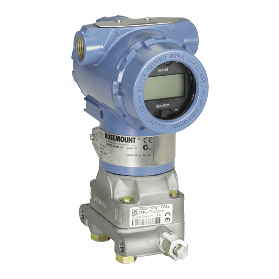
- Page 1 Manual 00809-0100-4007, Rev BD March 2023 Rosemount ™ 3051 Pressure Transmitter with 4-20 mA HART Protocol ®...
- Page 2 NOTICE Replacement equipment Replacement equipment or spare parts not approved by Emerson for use as spare parts could reduce the pressure retaining capabilities of the transmitter and may render the instrument dangerous. Use only bolts supplied or sold by Emerson as spare parts.
- Page 3 Severe changes in the electrical loop may inhibit HART Communication or the ability to reach alarm values. ® Therefore, Emerson absolutely cannot warrant or guarantee that the correct Failure alarm level (High or Low) can be read by the host system at the time of annunciation. NOTICE Nuclear applications The products described in this document are not designed for nuclear-qualified applications.
-
Page 5: Table Of Contents
Operation and maintenance....................75 5.1 Overview.............................75 5.2 Safety messages........................75 5.3 Recommended calibration tasks..................... 75 5.4 Calibration overview......................... 76 5.5 Trimming the pressure signal....................80 5.6 Trimming the analog output....................81 Chapter 6 Troubleshooting........................85 6.1 Overview.............................85 6.2 Safety messages........................85 6.3 Troubleshooting for 4-20 mA output..................85 6.4 Diagnostic messages........................ 87 Emerson.com/Rosemount... - Page 6 6.6 Reassemble the transmitter.....................95 6.7 Service support.......................... 98 Chapter 7 Safety Instrumented Systems (SIS) requirements..............99 7.1 Identify Rosemount 3051 safety certification................99 7.2 Installation in Safety Instrumented Systems (SIS) applications.......... 99 7.3 Configuring in Safety Instrumented Systems (SIS) applications........100 7.4 Safety Instrumented Systems (SIS) operation and maintenance........101 7.5 Inspection..........................103...
-
Page 7: Chapter 1 Introduction
Manual Introduction 00809-0100-4007 March 2023 1 Introduction 1.1 Models covered The following Rosemount 3051 Transmitters are covered by this manual: • Rosemount 3051C Coplanar Pressure Transmitter ™ — Measures differential and gauge pressure up to 2000 psi (137.9 bar). — Measures absolute pressure up to 4000 psia (275.8 bar). - Page 8 Introduction Manual March 2023 00809-0100-4007 Rosemount 3051...
-
Page 9: Chapter 2 Configuration
Refer to Safety messages. 2.3 System readiness If using HART -based control or asset management systems, confirm the HART capability ® of such systems prior to commissioning and installation. Not all systems can communicate with HART Revision 7 devices. Emerson.com/Rosemount... - Page 10 Device driver file names use device and DD Revision,such as 10_01. The HART protocol is designed to enable legacy device driver revisions to continue to communicate with new HART devices. To access new functionality, you must download the new device driver. Emerson recommends downloading new device driver files to ensure full functionality.
-
Page 11: Configuration Tools
Quick Service buttons • Local operator interface (LOI) Table 2-2: Power supply and resistance by communicator type Communicator Power supply Resistor AMS Device Manager ≥16.6 Vdc ≥250Ω AMS Trex (HART ≥16.6 Vdc ® ≥250Ω AMS Trex (HART + pwr) None None Emerson.com/Rosemount... - Page 12 Device driver (DD) menu trees 2.4.4 Configuring with the Quick Service buttons You can use the Quick Service buttons for the following configuration and maintenance tasks. • View Configuration • Zero • Rerange/Span • Loop Test • Flip Screen Rosemount 3051...
- Page 13 To activate the LOI, push either Configuration button. Configuration buttons are located on the LCD display or underneath the top tag of the transmitter. See Figure 2-3 for configuration button locations and Table 2-4 configuration button functionality. Remove the housing cover to access the LCD display. Emerson.com/Rosemount...
-
Page 14: How To Configure
Local Operator Interface (LOI). 2.5 How to configure Each unique application of the Rosemount 3051 may require different steps to commission and configure the transmitter. This section provides an overview of the procedures to perform common configuration tasks on your transmitter. 2.5.1 ... - Page 15 Manual Configuration 00809-0100-4007 March 2023 2.5.2 Verifying configuration parameters Emerson recommends that you verify the following configuration parameters prior to installation into the process. • Alarm and saturation levels • Damping • Process variables • Range values • • Transfer function •...
- Page 16 Low Flow Cut-off at four percent and a Low Flow Cut-in of five percent of the square root analog output range. Emerson recommends using application-specific configuration to configure differential pressure (DP) flow applications. Refer to...
- Page 17 In practice, you can change the transmitter range values as often as necessary to reflect changing process requirements. For a complete listing of range and sensor limits, refer to the Specifications section of the Rosemount 3051 Product Data Sheet. Select from one of the methods below to rerange the transmitter. Each method is unique;...
- Page 18 0 - 60 seconds. Damping with a communication device Procedure Go to Device Settings → Output → [pick the output you want to set damping for (such as Pressure or Level)] → Setup → Damping. Rosemount 3051...
- Page 19 The graphical LCD display gives you more options to choose from when customizing the display. The display will alternate between the selected items. • Pressure • Module temperature • Percent of range • Analog output • Level • Volume • Flow rate • Totalized flow • HART long tag ® Emerson.com/Rosemount...
- Page 20 You can also rotate the display manually in 90 degree increments to meet installations requiring a 90 degree or 270 degree rotation. Configure the graphical LCD display with a communication device Procedure Go to Device Settings → Display → Display → Display Parameters. Rosemount 3051...
-
Page 21: Application Specific Configuration
Go to Device Settings → Output → Flow → Setup → Configure Flow. Configuring low flow cut-off Emerson highly recommends using the low flow cut-off function to have a stable output and avoid problems due to process noise at a low flow or no flow condition. There are two key definitions to aid in understanding low flow cut-off: The pressure at which the field device will stop measuring the flow rate. - Page 22 For a flow rate of USGPH, the totalizer unit would be USGAL, and the flow unit of time would be hours. The flow unit is displayed on the communication device for convenience when you configure totalized flow on a communication device. Rosemount 3051...
- Page 23 2. Once the totalizer is configured and you are ready to begin totalizing, do the following: a) Go to Device Settings → Output → Totalizer → Control. b) Set the Totalizer Mode value to Stopped c) Run the Clear Totalizer method. d) Set the Totalizer Mode value to Totalizing Emerson.com/Rosemount...
- Page 24 To simplify configuration and to capture the unique applications that are associated with level measurement, Emerson recommends using the built-in level configurator to quickly and easily configure the transmitter to measure level. Level configuration parameters...
- Page 25 10 feet above. The Level Configurator method walks you through the configuration to establish the pressure at both minimum and maximum level. Figure 2-7: Level Configurator unit information screen Figure 2-8: Level Configurator tank configuration screen Emerson.com/Rosemount...
- Page 26 March 2023 00809-0100-4007 Figure 2-9: Level Configurator technology screen Figure 2-10: Level Configurator Water Return screen After you complete the Level Configurator method, you can view the Level Output screen to confirm that the values are set as expected. Rosemount 3051...
- Page 27 Adjust the level reading on the Level Configuration window. • Use a strapping table to configure the level and volume relationship. The Configure Tank method creates a relationship between level and volume using the following parameters: User-selectable tank geometry Tank type • Sphere • Vertical bullet Emerson.com/Rosemount...
-
Page 28: Detailed Transmitter Setup
The Rosemount 3051 Transmitter automatically and continuously performs self-diagnostic routines. If the self-diagnostic routines detect a failure, the transmitter drives the output to configured alarm and value based on the position of the alarm switch. - Page 29 Manual Configuration 00809-0100-4007 March 2023 (continued) Table 2-6: Rosemount 3051 alarm and saturation values Level 4-20 mA saturation 4-20 mA alarm High 20.8 mA ≥ 21.75 mA Table 2-7: NAMUR-compliant alarm and saturation values Level 4-20 mA saturation 4-20 mA alarm 3.8 mA...
- Page 30 A user-defined range, entered in the same units as the Monitored Device Deadband Variable, beyond the Alert Value trigger when a process alert will not be enunciated. Rosemount 3051...
- Page 31 2. Map the secondary variable, tertiary variable, and quaternary variable by going to Device Settings → Communication → HART → Variable Mapping. Re-map the primary variable with the local operator interface (LOI) Procedure 1. Click either button to activate the LOI. 2. Go to Extended Menu → Assign PV. Emerson.com/Rosemount...
-
Page 32: Configure Via Bluetooth ® Wireless Technology
® Procedure 1. Launch AMS Device Configurator. AMS Device Configurator for Emerson Field Devices. 2. Click on the device you want to connect to. 3. On first connection, enter the key for this device. 4. At the top left, click the menu icon to navigate the desired device menu. - Page 33 D. 20 mA Overview Emerson ships the transmitter with Loop Integrity off as default and without any loop characterization performed. Once the transmitter is installed and powered up, you must perform a loop characterization for the Loop Integrity diagnostic to function.
- Page 34 Severe changes in the electrical loop may inhibit HART communication or the ability to ® reach alarm values. Therefore, Emerson cannot absolutely warrant or guarantee that the correct Failure alarm level (High or Low) can be read by the host system at the time of annunciation.
- Page 35 Manual Configuration 00809-0100-4007 March 2023 NOTICE Emerson does not recommend the loop integrity diagnostic for transmitters operating in multidrop mode. Loop integrity action When the voltage deviation exceeds the set limit, you can configure three possible actions: • Disable Diagnostic •...
- Page 36 Configuration Manual March 2023 00809-0100-4007 Figure 2-15: Changes in process noise or variability and effect on statistical parameters Standard deviation increases or decreases with changing noise level. A. Process noise B. Standard deviation C. Mean D. Time (minutes) Rosemount 3051...
- Page 37 Procedure 1. Go to Diagnostics → Alerts → Plugged Impulse Line Diagnostic → Settings → Configure Plugged Impulse Line Diagnostic. 2. Select a notification mode: • HART alert ® • Analog Output Alarm 3. Select if the transmitter is installed in a flow application or not. Emerson.com/Rosemount...
-
Page 38: Performing Transmitter Tests
The analog loop test command verifies the output of the transmitter, the integrity of the loop, and the operations of any recorders or similar devices installed in the loop. Emerson recommends that you verify the 4-20 mA points in addition to alarm levels when installing, repairing, or replacing a transmitter. -
Page 39: Configuring Burst Mode
Burst mode applies only to the transmission of dynamic data and does not affect the way other transmitter data is accessed. However, when activated, Burst mode can slow down communication of non-dynamic data to the host by 50 percent. Emerson.com/Rosemount... -
Page 40: Establishing Multidrop Communication
® they do for a transmitter in a standard point-to-point installation. Figure 2-17 shows a typical multidrop network. This figure is not intended as an installation diagram. Rosemount 3051... - Page 41 A. HART modem B. Power supply Emerson sets the Rosemount 3051 to address zero (0) at the factory, which allows operation in the standard point-to-point manner with a 4-20 mA output signal. To activate multidrop communication, you must change the transmitter address to a number from 1 to 63.
- Page 42 Procedure 1. Go to Utility → Configure HART Application. 2. Select Polling Addresses. 3. Enter 0-63. Communicate with a multidropped transmitter using Asset Management Solutions (AMS) Device Manager Procedure 1. Click the HART modem icon. 2. Select Scan All Devices. Rosemount 3051...
-
Page 43: Chapter 3 Hardware Installation
3 Hardware installation 3.1 Overview The information in this section covers installation considerations for the Rosemount 3051 with HART protocol. Emerson ships a Quick Start Guide with every transmitter to describe ® recommended pipe-fitting and wiring procedures for each initial installation. - Page 44 Output damping At the factory, Emerson sets the output damping for the Rosemount 3051CD0 to 3.2. If the transmitter output is still noisy, increase the damping time. If you need a faster response, decrease the damping time.
-
Page 45: Installation Procedures
3.4 Installation procedures 3.4.1 Mount the transmitter For dimensional drawing information refer to the Dimensional Drawings section of the Rosemount 3051 Product Data Sheet. Process flange orientation Mount the process flanges with sufficient clearance for process connections. For safety reasons, place the drain/vent valves so the process fluid is directed away from possible human contact when the vents are used. - Page 46 Always ensure a proper seal by installing the electronics housing cover(s) so that metal contacts metal. Use Rosemount O-rings. Flange bolts Emerson can ship the Rosemount 3051 with a coplanar flange or a traditional flange installed with four 1.75-in. flange bolts. Table 3-1...
- Page 47 A. Differential transmitter B. Gauge/absolute transmitter C. Drain/vent D. Vented fitting E. 1.75 in. (44 mm) x 4 F. 1.50 in. (38 mm) x 4 Dimensions are in inches (millimeters). For gauge and absolute transmitters: 150 (38) x 2 Emerson.com/Rosemount...
- Page 48 Description Quantity Size in. (mm) Differential pressure Flange bolts 1.75 (44) Flange/adapter 2.88 (73) Gauge/absolute pressure Flange bolts 1.75 (44) Flange/adapter bolts 2.88 (73) Rosemount 3051T Transmitters are direct mount and do not require bolts for process connection. Rosemount 3051...
- Page 49 Dimensions are in inches (millimeters). Figure 3-6: Panel mounting bracket option codes B2 and B8 A. Mounting holes 0.375 diameter (10) Dimensions are in inches (millimeters). Figure 3-7: Flat mounting bracket option codes B3 and BC Dimensions are in inches (millimeters). Emerson.com/Rosemount...
- Page 50 Table 3-2: Mounting brackets Option Process connections Mounting Materials code In-Line Tradi- Pipe Panel Flat Carbon Stainless CS bolts SST bolts planar tional mount mount panel steel steel mount (CS) (SST) bracket bracket Rosemount 3051...
- Page 51 C. ⅜-in.-16 x 1¼-in. bolts for mounting to transmitter D. 2.8 (71) Dimensions are in inches (millimeters). Carbon steel (CS) head markings Stainless steel (SST) head markings Alloy K-500 head marking The last digit in the FS93_ head marking may be any letter between A and M. Emerson.com/Rosemount...
- Page 52 In steam service above 250 °F (121 °C), fill impulse lines with water to prevent steam from contacting the transmitter directly and to ensure accurate measurement start-up. NOTICE For steam or other elevated temperature services, it is important that temperatures at the process connection do not exceed the transmitter’s process temperature limits. Rosemount 3051...
- Page 53 Density variations between the legs The best location for the transmitter in relation to the process pipe is dependent on the process. Use the following guidelines to determine transmitter location and placement of impulse piping. • Keep impulse piping as short as possible. Emerson.com/Rosemount...
- Page 54 Do not attempt to loosen or remove flange bolts while the transmitter is in service. Use plant-approved lubricant or sealant when making the process connections. Refer to the Dimensional drawings section of the Rosemount 3051 Product Data Sheet for the distance between pressure connections. You can vary the distance by ±¼-in. (6.4 mm) by rotating one or both of the flange adapters.
- Page 55 NOTICE Electronics damage Rotation between the sensor module and the process connection can damage the electronics. Do not apply torque directly to the sensor module. To avoid damage, apply torque only to the hex-shaped process connection. See Figure 3-11. Emerson.com/Rosemount...
- Page 56 Rosemount 305, 306, and 304 Manifolds The Rosemount 305 Integral Manifold is available in two designs: Traditional and Coplanar. You can mount the traditional Rosemount 305 Integral Manifold to most primary elements with mounting adapters in the market today. Rosemount 3051...
- Page 57 2. Install the Integral Manifold on the sensor module. Use the four 2.25-in. (57.2 mm). manifold bolts for alignment. Finger tighten the bolts; then tighten the bolts incrementally in a cross pattern as seen in Figure 3-13 to final torque value. Flange bolts for complete bolt installation and torque values. Emerson.com/Rosemount...
- Page 58 Flange bolts for complete bolt installation information and torque values. When fully tightened, the bolts should extend through the top of the sensor module housing. 3. Leak-check assembly to maximum pressure range of transmitter. Rosemount 3051...
- Page 59 C. Equalize (closed) D. Process E. Isolate (open) F. Drain/vent valve Procedure 1. To zero the Rosemount 3051, close the block valve to the low pressure (downstream) side first. A. Drain/vent valve B. Isolate (open) C. Equalize (closed) D. Process E.
- Page 60 4. Open the block valve on the low pressure side of the transmitter to return the transmitter to service. A. Drain/vent valve B. Isolate (open) C. Equalize (closed) D. Process E. Isolate (open) F. Drain/vent valve Zero a five-valve natural gas manifold Five-valve natural gas configurations shown: Rosemount 3051...
- Page 61 1. Close the block valve on the low pressure (downstream) side of the transmitter. A. Test (plugged) B. Isolate (open) C. Process D. Equalize (closed) E. Equalize (closed) F. Drain vent (closed) G. Process H. Isolate (closed) I. Test (plugged) Emerson.com/Rosemount...
- Page 62 The manifold is now in the proper configuration for zeroing the transmitter. A. Test (plugged) B. Isolate (open) C. Process D. Equalize (open) E. Equalize (open) F. Drain vent (closed) G. Process H. Isolate (closed) I. Test (plugged) Rosemount 3051...
- Page 63 I. Test (plugged) 5. Close the equalize valve on the high pressure (upstream) side. A. Test (plugged) B. Isolate (open) C. Process D. Equalize (closed) E. Equalize (closed) F. Drain vent (closed) G. Process H. Isolate (closed) I. Test (plugged) Emerson.com/Rosemount...
- Page 64 6. To return the transmitter to service, open the low side isolation valve. A. Test (plugged) B. Isolate (open) C. Process D. Equalize (closed) E. Equalize (closed) F. Drain vent (closed) G. Process H. Isolate (open) I. Test (plugged) Rosemount 3051...
-
Page 65: Chapter 4 Electrical Installation
4 Electrical installation 4.1 Overview The information in this section covers installation considerations for the Rosemount 3051 Transmitter. A Quick Start Guide is shipped with every transmitter to describe pipe-fitting, wiring procedures, and basic configuration for initial installation. Related information... - Page 66 Carefully align pins for insertion into the output board. 4. Re-insert screws. 5. Reattach transmitter housing cover. Ensure that the cover is fully engaged to comply with explosion-proof requirements. 6. Re-attach power and return loop to automatic control. Rosemount 3051...
-
Page 67: Configuring Transmitter Security
Quick Service buttons. For 90 degree and 270 degree orientation, the physical display rotation is still required. 4.4 Configuring transmitter security There are three ways to manage security with the Rosemount 3051 Transmitter. • Security switch •... -
Page 68: Move Alarm Switch
3. Use a small screwdriver to slide the switch to the Lock position. 4. Reattach transmitter housing cover. Emerson recommends tightening the cover until there is no gap between the cover and housing to comply with explosion proof requirements. 4.4.2 ... -
Page 69: Electrical Considerations
Mount the transmitter with the electrical housing positioned downward for drainage. To avoid moisture accumulation in the housing, install wiring with a drip loop and ensure the bottom of the drip loop is mounted lower than the conduit connections of the transmitter housing. Figure 4-3 shows recommended conduit connections. Emerson.com/Rosemount... - Page 70 The total resistance load is the sum of the resistance of the signal leads and the load resistance of the controller, indicator, I.S. barriers, and related pieces. If you use intrinsic safety barriers, include the resistance and voltage drop. Rosemount 3051...
- Page 71 Signal wiring supplies all power to the transmitter. 2. For a 4-20 mA HART output, connect the positive lead to the terminal marked pwr/ ® comm+ and the negative lead to the terminal marked pwr/comm-. Emerson.com/Rosemount...
- Page 72 Connected to a good earth ground at the power supply end. 3. Reattach the field terminals housing cover. The cover must be fully engaged to comply with explosion-proof requirements. At terminations outside the transmitter housing, verify the cable shield drain wire is continuously connected. Rosemount 3051...
- Page 73 Internal ground connection: The internal ground connection screw is inside the FIELD TERMINALS side of the electronics housing. This screw is identified by a ground symbol ). The ground connection screw is standard on all Rosemount 3051 Transmitters. Refer to Figure 4-7.
- Page 74 You can order the transient protection terminal block as an installed option (option code T1) or as a spare part to retrofit existing transmitters in the field. See the Spare parts section of the Rosemount 3051 Product Data Sheet for part numbers. The lightning bolt symbol shown in Figure 4-9 identifies the transient protection terminal block.
-
Page 75: Operation And Maintenance
If any trim is done improperly or with inaccurate equipment, it may degrade the transmitter's performance. Emerson calibrates absolute pressure transmitters (Rosemount 3051CA and 3051TA) at the factory. Trimming adjusts the position of the factory characterization curve. Emerson provides instructions to perform configuration functions with the following: •... -
Page 76: Calibration Overview
5.4 Calibration overview NOTICE Emerson fully calibrates the Rosemount 3051 Pressure Transmitter at the factory. Emerson provides a field calibration option to meet plant requirements or industry standards. NOTICE Sensor calibration allows you to adjust the pressure (digital value) reported by the transmitter to be equal to a pressure standard. - Page 77 Monitor all configuration changes by looking at a display or by measuring the loop output. Table 5-1 shows the physical differences between the two sets of buttons. Table 5-1: Local configuration button options Local operator interface (LOI) and Quick Service Digital Zero Trim - gray retainer buttons- green retainer Emerson.com/Rosemount...
- Page 78 3. Calculate the total probable error (TPE). 4. Calculate the stability per month. 5. Calculate the calibration frequency. Sample calculation for Rosemount 3051 (0.04 percent accuracy and ten-year stability) The following is an example of how to calculate calibration frequency.
- Page 79 5.4.3 Compensating for span line pressure effects (Range 4 and Rosemount 3051 Range 4 and 5 Pressure Transmitters require a special calibration procedure when used in differential pressure applications. The purpose of this procedure is to optimize transmitter performance by reducing the effect of static line pressure in these applications.
-
Page 80: Trimming The Pressure Signal
Always adjust the low trim value first to establish the correct offset. Adjustment of the high trim value provides a slope correction to the characterization curve based on the low trim value. The trim values help optimize performance over a specific measurement range. Rosemount 3051... -
Page 81: Trimming The Analog Output
4 and 20 mA points to match the plant standards. Perform this trim after the digital to analog conversion, so that it only affects the 4-20 mA analog signal. Figure 5-2 Figure 5-3 graphically show the two ways the characterization curve is affected when an analog output trim is performed. Emerson.com/Rosemount... - Page 82 Operation and maintenance Manual March 2023 00809-0100-4007 Figure 5-2: 4-20 mA output trim - zero/lower trim A. Before trim B. After trim C. Meter reading D. mA output Rosemount 3051...
- Page 83 If you add a resistor to the loop, ensure that the power supply is sufficient to power the transmitter to a 20 mA output with additional loop resistance. Refer to Power supply for a 4-20 mA HART ® Perform a 4-20 mA output trim with a communication device Procedure Go to Device Settings → Calibration → Analog Output → Calibration → Analog Calibration. Emerson.com/Rosemount...
- Page 84 This command can be useful for recovering from an inadvertent trim, incorrect plant standard, or faulty meter. Recall factory trim - analog output with a communication device Procedure Go to Device Settings → Calibration → Analog Calibration → Factory Calibration → Restore Analog Calibration. Rosemount 3051...
-
Page 85: Chapter 6 Troubleshooting
4. Verify clean DC power to transmitter (maximum AC noise 0.2 volts peak to peak). 5. Verify the output is between 4 and 20 mA or saturation levels. 6. Use the communication device to poll for all addresses. Emerson.com/Rosemount... - Page 86 Milliamp reading is erratic Recommended actions 1. Verify power source to transmitter has adequate voltage and current. 2. Check for external electrical interference. 3. Verify transmitter is properly grounded. 4. Verify shield for twisted pair is only grounded at one end. Rosemount 3051...
-
Page 87: Diagnostic Messages
There are no pressure updates from the sensor to the electronics. Sensor Communication Failure Graphical LCD display NO P UPDATE LCD display NO PRESS UPDATE Local operator interface (LOI) Recommended actions 1. Ensure the sensor cable connection to the electronics is tight. 2. Replace the pressure sensor. Emerson.com/Rosemount... - Page 88 Restart the device. Loop Test Current Fixed The analog output is fixed and does not represent the process measurement due to the device being set to loop test mode. Loop Test Current Fixed Graphical LCD display ANLOG FIXED LCD display Rosemount 3051...
- Page 89 The loop current is saturated due to the analog value being outside the saturation value range, or the primary variable is being saturated.. Graphical LCD Loop Current Saturated display ANLOG SAT LCD display Local operator ANALOG SAT interface (LOI) Emerson.com/Rosemount...
- Page 90 The plugged impulse line diagnostic has detected a change in process noise levels, which could be attributed to a plugged impulse line, plugged flow element, or agitation loss. Graphical LCD Plugged Impulse Line Diagnostic display Plug Line LCD display Local operator Plugged Line interface (LOI) Rosemount 3051...
- Page 91 3. Replace the electronic circuit board. Loop Integrity Diagnostic The Loop Integrity Diagnostic has detected a deviation of the terminal voltage outside of the configured limits. This may indicate degraded or loop integrity. Loop Integrity Diagnostic Graphical LCD display Emerson.com/Rosemount...
- Page 92 Bluetooth alert. Bluetooth Electronics Error Graphical LCD display LCD display Local operator interface (LOI) Recommended actions 1. Remove the front housing cover (considering hazardous location requirements). 2. Replace the display (which contains the Bluetooth electronics). 3. Restart the device. Rosemount 3051...
-
Page 93: Disassembling The Transmitter
You may reuse undamaged O-rings. 6.5.2 Remove terminal block Electrical connections are located on the terminal block in the compartment labeled FIELD TERMINALS. Procedure 1. Remove the housing cover from the field terminal side. Emerson.com/Rosemount... - Page 94 3. Using a 5/64-in. hex wrench, loosen the housing rotation set screw one full turn. 4. Unscrew the module from the housing, making sure the black cap on the sensor module and sensor cable do not catch on the housing. Rosemount 3051...
-
Page 95: Reassemble The Transmitter
Ensure the power posts from the electronics housing properly engage the receptacles on the electronics board. Do not force. The electronics board should slide gently on the connections. 3. Tighten the captive mounting screws. 4. Replace the electronics housing cover. Emerson.com/Rosemount... - Page 96 • Coplanar process flange with flange adapters: a. Hold the process flange in place by installing the two alignment screws to finger tightness (screws are not pressure retaining). Do not over-tighten, as this will affect module-to-flange alignment. Rosemount 3051...
- Page 97 NOTICE Take care to place the opening on the valve so that process fluid will drain toward the ground and away from human contact when the valve is opened. 2. Tighten the drain/vent valve to 250 in.-lb. (28.25 N-m). Emerson.com/Rosemount...
-
Page 98: Service Support
For inquiries outside of the United States, contact the nearest Emerson representative for RMA instructions. To expedite the return process outside of the United States, contact the nearest Emerson representative. WARNING Hazardous substances Individuals who handle products exposed to a hazardous substance may be injured. -
Page 99: Safety Instrumented Systems (Sis) Requirements
There are no additional instructions for installing the transmitter in SIS applications. WARNING Only allow qualified personnel to install the Rosemount 3051 in SIS applications. Always ensure a proper seal by installing the electronics housing cover(s) so that metal contacts metal. -
Page 100: Configuring In Safety Instrumented Systems (Sis) Applications
Use any HART capable configuration tool to communicate with and verify configuration of ® the Rosemount 3051. NOTICE Transmitter output is not safety-rated during the following: configuration changes, multidrop, and loop test. Use alternative means to ensure process safety during transmitter configuration and maintenance activities. -
Page 101: Safety Instrumented Systems (Sis) Operation And Maintenance
7.4.2 Perform a guided proof-test If you select the guided proof-test option, the Rosemount 3051 will support a feature that can perform a guided partial or comprehensive proof-test. This feature walks you through the necessary steps to perform a proof-test. The alarm levels and required steps will be provided without the need to look them up. - Page 102 This tests for possible quiescent current related failures. This tests for compliance voltage problems, such as a low loop power supply voltage or increased wiring distance. This also tests for other possible failures. Rosemount 3051...
-
Page 103: Inspection
Only allow qualified personnel to repair the product and replace parts. 7.5.2 Rosemount 3051 Safety Instrumented Systems (SIS) reference Operate the Rosemount 3051 in accordance with the functional and performance specifications provided in the Specifications section of the Rosemount 3051 Product Data Sheet. - Page 104 Safety Instrumented Systems (SIS) requirements Manual March 2023 00809-0100-4007 Transmitter response time See the Specifications section of the Rosemount 3051 Product Data Sheet. At least once every 60 minutes Self-diagnostics test interval 7.5.5 Product life 50 years - based on worst case component wear-out mechanisms; not based on wear-out of process wetted materials.
-
Page 105: Appendix A Reference Data
Reference data A.1 Ordering information, specifications, and drawings To view current Rosemount 3051 ordering information, specifications, and drawings, follow these steps: Procedure 1. Go to Emerson.com/Rosemount3051CP. 2. Scroll as needed to the green menu bar and click Documents & Drawings. - Page 106 Reference data Manual March 2023 00809-0100-4007 Rosemount 3051...
-
Page 107: Appendix B Device Driver (Dd) Menu Trees
Manual Device driver (DD) menu trees 00809-0100-4007 March 2023 B Device driver (DD) menu trees Figure B-1: First level menu trees Emerson.com/Rosemount... - Page 108 Device driver (DD) menu trees Manual March 2023 00809-0100-4007 Figure B-2: Process Variables menu Figure B-3: Device Settings 1 Rosemount 3051...
- Page 109 Manual Device driver (DD) menu trees 00809-0100-4007 March 2023 Figure B-4: Device Settings 2 Emerson.com/Rosemount...
- Page 110 Device driver (DD) menu trees Manual March 2023 00809-0100-4007 Figure B-5: Device Settings 3 Rosemount 3051...
- Page 111 Manual Device driver (DD) menu trees 00809-0100-4007 March 2023 Figure B-6: Device Settings 4 Emerson.com/Rosemount...
- Page 112 Device driver (DD) menu trees Manual March 2023 00809-0100-4007 Figure B-7: Diagnostics 1 Rosemount 3051...
- Page 113 Manual Device driver (DD) menu trees 00809-0100-4007 March 2023 Figure B-8: Diagnostics 2 Emerson.com/Rosemount...
- Page 114 Device driver (DD) menu trees Manual March 2023 00809-0100-4007 Figure B-9: Maintenance 1 Rosemount 3051...
- Page 115 Manual Device driver (DD) menu trees 00809-0100-4007 March 2023 Figure B-10: Maintenance 2 Emerson.com/Rosemount...
- Page 116 Device driver (DD) menu trees Manual March 2023 00809-0100-4007 Rosemount 3051...
-
Page 117: Appendix C Quick Service Buttons
Trim to PV Zero Set current reading as 4 mA Rerange Set 4 mA Set 20 mA Loop Test Set 4 MA Set 8 MA Set 12 MA Set 16 MA Set 20 MA Flip screen Flip 180 Degrees Emerson.com/Rosemount... - Page 118 Quick Service buttons Manual March 2023 00809-0100-4007 Rosemount 3051...
-
Page 119: Appendix D Local Operator Interface (Loi)
13. Press the Enter button to select for the eight digit. 000011.2 The number entry is complete. A SAVE screen appears. Usage notes • To move backwards in the number, scroll to the Left arrow symbol and press Enter. Emerson.com/Rosemount... -
Page 120: Enter Text In The Local Operator Interface (Loi)
Enter numbers in the local operator interface (LOI), except the following characters are available in all locations: , space. NOTICE If the current text contains a character the LOI cannot display, it will be shown as an asterisk " ". Rosemount 3051... - Page 121 Manual 00809-0100-4007 March 2023 Emerson.com/Rosemount...
- Page 122 The Emerson logo is a trademark and service mark of Emerson Electric Co. Rosemount is a mark of one of the Emerson family of companies. All other marks are the property of their respective owners. The "Bluetooth" word mark and logos are registered trademarks owned by Bluetooth, SIG, Inc.