
Related Manuals for Emerson Rosemount 3051N


Summary of Contents for Emerson Rosemount 3051N
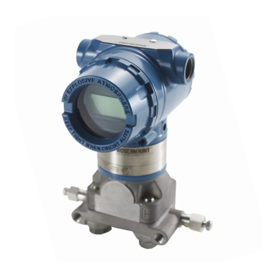
- Page 1 Reference Manual 00809-0100-4808, Rev DA October 2016 ™ Rosemount 3051N Smart Pressure Transmitter for Nuclear Service...
- Page 2 This page intentionally left blank...
-
Page 3: Table Of Contents
Reference Manual Contents 00809-0100-4808, Rev DA October 2016 1Section 1: Introduction Using this manual ..............1 2Section 2: Transmitter Functions Overview . - Page 4 Digital-to-analog trim using other scale ........21 2.12.11 Compensating Rosemount 3051N Range 4 and 5 Differential Transmitters for 2.12.12 line pressure .
- Page 5 Configuration information ............48 Rosemount 3051N 4-20 mA/HART Output Smart Pressure Transmitters A.6.1...
- Page 6 Contents Reference Manual 00809-0100-4808, Rev DA October 2016 BAppendix B: Options Overview ............... . 51 Safety messages.
- Page 7 Chanhassen, MN 55317 Important The Rosemount 3051N Pressure Transmitter is qualified for nuclear use per IEEE Std 344-1987 and IEEE Std 323-1983 (mild environment) as documented in Rosemount Report D2001019, and is supplied in accordance with 10CFR50 Appendix B and ISO 9001:2008 quality assurance programs. To ensure compliance with 10CFR Part 21, the transmitter must comply with the requirements herein and in Report D2001019 throughout its installation, operation, and maintenance.
- Page 8 Title Page Reference Manual 00809-0100-4808, Rev DA October 2016 This page intentionally left blank viii Title Page...
-
Page 9: Using This Manual
Appendix C: HART® Communicator provides an overview of the HART Communicator, defines its partial command menu tree for the Rosemount 3051N Family, and provides a table of typical Fast Key sequences. A table of typical diagnostic messages is also included. - Page 10 Reference Manual Introduction 00809-0100-4808, Rev DA October 2016 This page intentionally left blank Introduction...
-
Page 11: Overview
Reference Manual Transmitter Functions 00809-0100-4808, Rev DA October 2016 Section 2 Transmitter Functions Overview ............... . page 3 Safety messages . -
Page 12: Failure Mode Alarm
October 2016 Failure mode alarm Rosemount 3051N Transmitters automatically and continuously perform self-diagnostic routines. If the self-diagnostic routines detect a failure, the transmitter drives its output outside of the normal saturation values. The transmitter will drive its output low or high based on the position of the failure mode alarm jumper. -
Page 13: Security Jumper (Write Protect)
Reference Manual Transmitter Functions 00809-0100-4808, Rev DA October 2016 2.4.1 Security jumper (write protect) You can prevent changes to the transmitter configuration data with the write protection jumper. Security is controlled by the security (write protect) jumper located on the electronics board or meter face. -
Page 14: Commissioning Transmitter With A Hart-Based Communicator
Commissioning consists of testing the transmitter and verifying transmitter configuration data. You may commission Rosemount 3051N Transmitters either before or after installation. Commissioning the transmitter on the bench before installation using a HART-based Communicator ensures that all transmitter components are in good working order and acquaints you with the operation of the device. -
Page 15: Wiring Diagrams (Bench Hook-Up)
Reference Manual Transmitter Functions 00809-0100-4808, Rev DA October 2016 2.6.2 Wiring diagrams (bench hook-up) Connect the bench equipment as shown in Figure 2-3 and turn on the HART-based Communicator by pressing the ON/OFF key. The communicator will search for a HART-compatible device and will indicate when the connection is made. -
Page 16: Review Configuration Data
Transmitter Functions Reference Manual 00809-0100-4808, Rev DA October 2016 Do not use inductive-based transient protectors. Note Signal point may be grounded at any point or left ungrounded Review configuration data HART Fast Keys 1, 5 Note Information and procedures in this section that make use of HART Communicator Fast Key sequences assume that the transmitter and communicator are connected, powered, and operating correctly. -
Page 17: Check Output
For example, if the 4 and 20 mA points are set to 0 and 10 in H on a range code 1 Rosemount 3051N Transmitter, and the transmitter detects a pressure of 25 inH... -
Page 18: Set Output
Activate the transmitter square root output option to make the analog output proportional to flow. As the input approaches zero, the Rosemount 3051N Transmitter automatically switches to a linear output in order to ensure a more smooth, stable output near zero. See Figure 2-5. -
Page 19: Rerange With A Communicator Only
Reference Manual Transmitter Functions 00809-0100-4808, Rev DA October 2016 2.9.4 Rerange with a communicator only HART Fast Keys 1, 2, 3, 1, 1 Reranging using only the communicator changes the values of the analog 4 and 20 mA points independently without a pressure input. Note Changing the lower or upper range point results in similar changes to the span. -
Page 20: Damping
Transmitter Functions Reference Manual 00809-0100-4808, Rev DA October 2016 To rerange the transmitter using the span and zero buttons, perform the following procedure. 1. Loosen the screw holding the label on top of the transmitter housing, and rotate the label to expose the zero and span buttons (see Figure 2-6 on page 12). -
Page 21: Lcd Display Meter Options
Reference Manual Transmitter Functions 00809-0100-4808, Rev DA October 2016 2.9.8 LCD display meter options HART Fast Keys 1, 4, 3, 4 The Meter Options command allows you to customize the LCD display meter for use in your application. The meter can be configured to display the following information: Engineering units ... -
Page 22: Transmitter Test
Transmitter Functions Reference Manual 00809-0100-4808, Rev DA October 2016 2.11.1 Transmitter test HART Fast Keys 1, 2, 1, 1 The transmitter Self Test command initiates a more extensive diagnostics routine than that performed continuously by the transmitter. The transmitter test routine can quickly identify potential electronics problems. -
Page 23: Calibration
Reference Manual Transmitter Functions 00809-0100-4808, Rev DA October 2016 2.12 Calibration Calibrating a smart transmitter is different from calibrating an analog transmitter. The one-step calibration process of an analog transmitter is done in three steps with a smart transmitter. Rerange—sets the 4 and 20 mA points at the desired pressures; ... -
Page 24: Calibration Overview
Note A HART Communicator is required for all sensor and output trim procedures. Rosemount 3051N Transmitter Range 4 and Range 5 Transmitters require a special calibration procedure when used in differential pressure applications under high static line pressure (see “Compensating Rosemount 3051N Range 4 and 5 Differential Transmitters for line pressure”... -
Page 25: Deciding Which Trim Procedure To Use
Reference Manual Transmitter Functions 00809-0100-4808, Rev DA October 2016 Figure 2-7. Transmitter Data Flow with Calibration Options Transmitter Ranged 0 to 100 inH 20.00 mA 3051:PT-4001 Online 1 áDevice Setup 2PV100.00 inH2O 3AO20.00 mA 4LRV0.00 inH2O 5URV100.00 inH2O A. Sensor F. -
Page 26: Sensor Trim
Note Do not perform a zero trim on Rosemount 3051N Absolute Pressure Transmitters. A zero trim is zero-based, and absolute pressure transmitters reference absolute zero. To correct mounting position effects on a Rosemount 3051N Absolute Pressure Transmitter, perform a low trim within the full sensor trim function. -
Page 27: Full Trim
Reference Manual Transmitter Functions 00809-0100-4808, Rev DA October 2016 Note The transmitter must be within three percent of true zero (zero-based) in order to calibrate it using the zero trim function. 3. Follow the commands provided by the communicator to complete the adjustment of the zero trim. 2.12.5 Full trim HART Fast Keys... -
Page 28: Recall Factory Trim
A. Dead weight tester (calibration standard for sensor trim only) B. HART-based communicator C. 250 ohm minimum loop resistance D. 24 Vdc power supply E. Rosemount 3051N Pressure Transmitter F. Precision meter 2.12.6 Recall factory trim The Recall Factory Trim commands allow the restoration of the as-shipped factory settings of the sensor trim and analog output trim. -
Page 29: Digital-To-Analog Trim
Reference Manual Transmitter Functions 00809-0100-4808, Rev DA October 2016 2.12.10 Digital-to-analog trim 1, 2, 3, 2, 1 HART Fast Keys To perform a digital-to-analog trim with a HART Communicator, perform the following procedure. 1. From the ONLINE screen, select 1 Device Setup > 2 Diag/Service > 3 Calibration > 2 Trim Analog Output >... -
Page 30: Compensating Rosemount 3051N Range 4 And 5 Differential Transmitters For Line Pressure
Correctable to ±0.2% of reading per 1000 psi for line pressures from 0 to 3626 psi. The systematic span shift caused by the application of static line pressure is –1.00% of input reading per 1000 psi for Rosemount 3051N Range 4 transmitters, and –1.25% of reading per 1000 psi for Range 5 transmitters. -
Page 31: Transmitter Functions
0 + (0.01/1000 psi)(1500 in H 0)(1200 psi) 1518 in H To complete a Rosemount 3051N Transmitter full trim, enter the corrected values for low trim (LT) and high trim (HT). Refer to “Full trim” on page Enter the corrected input values for low trim and high trim through the communicator keypad after applying the nominal value of pressure as the transmitter input. - Page 32 Reference Manual Transmitter Functions 00809-0100-4808, Rev DA October 2016 This page intentionally left blank Transmitter Functions...
-
Page 33: Overview
Use only components supplied with the Rosemount 3051N or sold by Rosemount Nuclear Instruments Inc. as spare parts for the Rosemount 3051N. - Page 34 Installation Reference Manual 00809-0100-4808, Rev DA October 2016 Figure 3-1. Typical Installation Flowchart START HERE Bench Calibration? Field Install Check Jumpers and Switches (page Configure Verify (Section Mount Transmitter (page Set Units Apply Pressure Wire Transmitter (page Set Range Points Within Specifications? Power Transmitter...
-
Page 35: General Considerations
Install the enclosed pipe plug in unused conduit openings with a minimum of five threads engaged to comply with explosion proof requirements. Mechanical considerations The following figures show dimensional drawings and installation examples of the Rosemount 3051N Transmitters including mounting brackets. 3.4.1 Rosemount 3051ND0 and 3051ND1 For Rosemount 3051ND0 and 3051ND1, mount the transmitter solidly to prevent tilting. -
Page 36: Steam Service
Keep drain/vent connections on the bottom for gas service and on the top for liquid service. 3.4.4 Independent seals The Rosemount 3051N Transmitter incorporates two independent seals between the process connection and the conduit connection. Figure 3-2. Coplanar Flange Mounting Configurations with Optional Bracket (Code B4) for Panel Mounting 2.81... - Page 37 Reference Manual Installation 00809-0100-4808, Rev DA October 2016 Figure 3-3. Rosemount 3051N Coplanar Flange Dimensional Drawing (Differential Pressure Transmitter Shown) A. Meter cover (optional) F. Terminal connections B. 0.75 (20) clearance for cover removal -18 NPT on coplanar flange for pressure connection C.
- Page 38 Installation Reference Manual 00809-0100-4808, Rev DA October 2016 Figure 3-4. Traditional Flange Mounting Configurations with Optional Brackets for Panel Mounting Option code BS: Traditional flange universal panel Option code B2: Traditional flange panel mounting mounting bracket (stainless steel) bracket (painted carbon steel) 2.81 (71) 2.81 (71) 2.81...
-
Page 39: Mounting
Note: Dimensions are nominal in inches (millimeters). 3.4.5 Mounting The Rosemount 3051N Pressure Transmitter weighs approximately 6.0 lb (2,7 kg) without additional options. For complete weight information, including options, see “Physical specifications” on page 45. Optional mounting brackets available with the Rosemount 3051N allow mounting to a panel or wall. - Page 40 Installation Reference Manual 00809-0100-4808, Rev DA October 2016 Dimensions and typical mounting configurations are contained in this section. Note The transmitter is calibrated in an upright position at the factory. If you mount the transmitter in any other position, the zero point will shift by an amount equivalent to the liquid head caused by the varied mounting position.
- Page 41 Reference Manual Installation 00809-0100-4808, Rev DA October 2016 Figure 3-6. Typical Installation Examples to Illustrate Transmitter and Impulse Piping Locations Gas or liquid service Gas service Steam service Impulse piping The piping between the process and the transmitter must accurately transfer the pressure to obtain accurate measurements.
-
Page 42: Process Connections
With 250 ohms of loop resistance, the transmitter will require a minimum of 16 volts to output 20 mA. If a single power supply is used to power more than one Rosemount 3051N Transmitter, the power supply used, and circuitry common to the transmitters, should not have more than 20 ohms of impedance at 1200 Hz. -
Page 43: Wiring
24 AWG or larger wire, and do not exceed 5000 feet (1500 meters). Do not use inductive-based transient protectors, including the Rosemount 470, as they can adversely affect the output of Rosemount 3051N 4–20 mA transmitters.The Rosemount 3051N includes the transient protection terminal block (T1) as standard. -
Page 44: Grounding The Transmitter Case
Rosemount 3051N Transmitters. External Ground Assembly: This assembly is included as standard with the transient protection terminal block (T1) included with the Rosemount 3051N. Note Grounding the transmitter case using the threaded conduit connection may not provide a sufficient ground. -
Page 45: Cover Installation
Reference Manual Installation 00809-0100-4808, Rev DA October 2016 3.6.2 Cover installation Always install the electronics housing covers metal-to-metal to ensure a proper seal. Installation... - Page 46 Reference Manual Installation 00809-0100-4808, Rev DA October 2016 This page intentionally left blank Installation...
-
Page 47: Overview
Reference Manual Troubleshooting 00809-0100-4808, Rev DA October 2016 Section 4 Troubleshooting Overview ............... . page 39 Safety messages . -
Page 48: Returning Rosemount Products And Materials
The Rosemount 3051N Smart Pressure Transmitter is supplied by Rosemount Nuclear Instruments, Inc. as a non-field repairable device to ensure its qualification status is maintained. The Rosemount 3051N must be returned to Rosemount Nuclear Instruments, Inc. (RNII) for repairs and/or failure analysis. -
Page 49: Nuclear Specifications
Specifications and Reference Data Reference Manual October 2016 00809-0100-4808, Rev DA Appendix A Specifications and Reference Data Nuclear specifications ............. page 41 Performance specifications . -
Page 50: Hydrostatic Testing
Reference Manual Specifications and Reference Data October 2016 00809-0100-4808, Rev DA (1)(2) A.1.5 Hydrostatic testing A.2.3 Ambient temperature effect Rosemount 3051ND/NG Model Range code Hydrostatic test pressure 750 psi Range code Ambient temperature effect per 50° F (28° C) 3051ND 2000 psi ±... -
Page 51: Static Pressure Effect
3626 psi (25 MPa) Max. Loop Resistance = 43.5 (Power Supply Voltage – 10.5) ohms 1. Ps equals static line pressure applied. 1935 2. Specification for Rosemount 3051N Range 0 is expressed in (% per 100 psi [689 KPa]). 1500 1000... -
Page 52: Span And Zero, Zero Elevation, And Suppression
Reference Manual Specifications and Reference Data October 2016 00809-0100-4808, Rev DA A.3.5 Span and zero, zero elevation, and suppression Zero and span values can be set anywhere within the range limits stated in Table A-2 Table A-3, providing sensor limits are not exceeded. -
Page 53: Maximum Working Pressure
Flange bolts pressure. Plated carbon steel, per ASTM A449, Type 1 or SAE J492 Grade 5 A.3.12 Overpressure limits (austenitic 316 SST per ASTM F593 for the Rosemount 3051N Transmitters withstand the following overpressure Range Code 0) without damage: Electronics housing... - Page 54 Reference Manual Specifications and Reference Data October 2016 00809-0100-4808, Rev DA Weight Transmitter without options: 6.0 lb (2,7 kg) (see table below for additional weights) Option Description Add: code Stainless steel housing 3.1 lb (1.4 kg) Traditional flange 2.4 lb (1.1 kg) LCD display meter for 0.5 lb (0.2 kg) aluminum housing...
-
Page 55: Ordering Information
Specifications and Reference Data Reference Manual October 2016 00809-0100-4808, Rev DA A.5 Ordering information Table A-4. Rosemount 3051N Differential, Gage, and Absolute Pressure Transmitters Ordering Information — = Not Applicable • = Applicable Model Transmitter type (select one) ND NG NA 3051ND Differential pressure transmitter •... -
Page 56: Configuration Information
3051ND 2 A 2 2 A 1 A B4 All Rosemount 3051N Transmitters are provided as standard with transient protection block (TI) and cleaning for < 1 PPM chloride. Rosemount 3051ND0 is available only with Process Flange Code 0 (Alternate Flange H2), O-ring Code A, and stainless steel process flange bolting. - Page 57 Specifications and Reference Data Reference Manual October 2016 00809-0100-4808, Rev DA A.6.1 Rosemount 3051N 4-20 A/HART Output Smart Pressure Transmitters Typical Configuration Data Worksheet Software Tag: |__|__|__|__|__|__|__|__| Output information: (software selectable) ___________________ 4 mA = Key to Symbols ____________________ Upper Range Limit H...
- Page 58 4–20 mA with simultaneous digital signal based on HART ProtocolH Note: This is the only signal selection that has been evaluated for use in safety related applications. Figure A-2. Rosemount 3051N Exploded View (with Coplanar Process Flange) A. Cover G. Electronics board K.
-
Page 59: Overview
3051N can ease installation, improve the security of control systems, and simplify use. Included in this section is a description of LCD display meter diagnostic messages. The Rosemount 3051N LCD display meter option is qualified to maintain structural integrity throughout the specified seismic event. Operation of the LCD display meter is not addressed for use during or after a seismic event. -
Page 60: Custom Meter Configuration
Reference Manual Options October 2016 00809-0100-4808, Rev DA B.3.1 Custom meter configuration The user-configurable scale is a feature that enables the LCD display meter to display flow, level, or custom pressure units. The meter can ® be configured using a HART Communicator (see Table C-1 on page 62). -
Page 61: Installing The Meter
B.3.2 Installing the meter For transmitters ordered with the LCD display meter, the meter is shipped installed. Installing the meter on an existing Rosemount 3051N Transmitter requires a small instrument screwdriver and the meter kit (when the kit is made available by Rosemount Nuclear Instruments, Inc.). -
Page 62: Diagnostic Messages
Electronics are able to verify alarm current levels. An alarm level test is recommended before returning the transmitter to service (see “Alarm level verification” on page Figure B-2. Rosemount 3051N with Optional LCD Display Meter B.3.3 Diagnostic messages In addition to the output, the LCD display meter displays abbreviated operation, error, and warning messages for troubleshooting the transmitter. -
Page 63: Warnings
Options Reference Manual October 2016 00809-0100-4808, Rev DA FAIL MODULE The sensor module is disconnected or is malfunctioning. Verify the sensor module ribbon cable is connected to the back of the electronics board. If the ribbon cable is properly connected, there is a problem within the sensor module. Possible sources of problems include: Pressure or temperature updates are not being received in the sensor module. -
Page 64: Operation
B.4 Mounting brackets Optional mounting brackets available with the Rosemount 3051N facilitate mounting to a panel. The standard bracket (B4) for use with the coplanar flange is stainless steel with stainless steel bolts. Refer to Figure 3-2 on page 28 for dimensions and mounting configurations. -
Page 65: Traditional Flange (H2)
00809-0100-4808, Rev DA B.4.1 Traditional flange (H2) The traditional flange option converts the mounting configuration of the Rosemount 3051N to one similar to traditional style transmitters. This allows the Rosemount 3051N to replace traditional transmitters without changing existing manifolds, impulse piping, or bracket arrangements. - Page 66 Reference Manual Options October 2016 00809-0100-4808, Rev DA This page intentionally left blank Options...
-
Page 67: Introduction
If YES is selected, the communicator will communicate properly with the transmitter using the existing Rosemount 3051N DDs. However, software features added since the revision of the DDs in the communicator will not be accessible. If NO is selected, the communicator will default to a generic transmitter functionality. -
Page 68: Safety Messages
Reference Manual HART Communicator October 2016 00809-0100-4808, Rev DA Safety messages Procedures and instructions in this section may require special precautions to ensure the safety of the personnel performing the operations. Information that raises potential safety issues is indicated by a warning symbol ( ). - Page 69 HART Communicator Reference Manual October 2016 00809-0100-4808, Rev DA FIGURE C-1. HART Communicator Typical Abbreviated Menu Tree Online 1 PROCESS 1 Pressure 1 Keypad Input Menu VARIABLE 2 Percent Range 2 Apply Values 1 DEVICE 3 Analog Output 1 Self Test SETUP 1 Digital-to-Analog Trim 4 Sensor...
- Page 70 Reference Manual HART Communicator October 2016 00809-0100-4808, Rev DA Table C-1. Typical HART Fast Key Sequences (partial listing) Function HART Fast Key sequence Alarm and Saturation Levels 1, 4, 2, 7 Analog Output Alarm Type 1, 4, 3, 2, 4 Custom Meter Configuration 1, 3, 7, 2 Custom Meter Value...
-
Page 71: Connections And Hardware
HART Communicator Reference Manual October 2016 00809-0100-4808, Rev DA Connections and hardware The HART Communicator can interface with a transmitter from the control room, the instrument site, or any wiring termination point in the loop through the communicator connections as shown in Figure C-2, Figure... - Page 72 Reference Manual HART Communicator October 2016 00809-0100-4808, Rev DA Figure C-4. 475 HART Communicator Terminal Access Door A. Access door B. Communication terminals C. HART communication terminal markings Figure C-5. Bench Hook-up (4–20 mA Transmitters) A. Current meter 250 ohms (necessary for HART communication only) B.
-
Page 73: Menus And Functions
Note Although the Rosemount 3051N has multi-drop capability, which is a HART protocol feature, the Rosemount 3051N is not qualified/dedicated for use in multi-drop mode. Once selecting a MAIN menu option, the HART Communicator provides the information needed to complete the operation. -
Page 74: Online Menu
C-1, an alphabetical listing of most online functions, to find the corresponding HART Fast Key sequences. These codes are applicable only to Rosemount 3051N Transmitters and the HART Communicator. For additional details, refer to the applicable HART Field Communicator User Manual. -
Page 75: Diagnostic Messages
HART Communicator Reference Manual October 2016 00809-0100-4808, Rev DA Diagnostic messages The following pages contain a list of messages used by the 275, 375, and 475 HART Communicators (HC) and their corresponding descriptions. Variable parameters within the text of a message are indicated with <variable parameter>. Reference to the name of another message is identified by [another message]. - Page 76 Reference Manual HART Communicator October 2016 00809-0100-4808, Rev DA Message Description Download data from Select the SEND softkey to transfer information from the communicator configuration memory to memory to the device. device Exceed field width Indicates the field width for the current arithmetic variable exceeds the device-specified description edit format.
- Page 77 SEND or LOSE data thrown away before connecting to another device. Upgrade 275 Field The communicator does not contain the most recent Rosemount 3051N Device Communicator software to Descriptors (DDs). Select YES to communicate using the existing DDs. Select access XMTR function.
- Page 78 HART Communicator Reference Manual October 2016 00809-0100-4808, Rev DA This page intentionally left blank HART Communicator...
- Page 79 Digital trim operation that allows adjustment of the output electronics to conform to the plant standard. Three types of analog output trim are available: 4–20 mA Trim, 4–20 mA Other Scale, and Low Power. “Analog output trim” on page 20. Low Power is not approved for use with the Rosemount 3051N. Cloning ®...
- Page 80 Note that although the Rosemount 3051N has multi-drop capability, which is a HART protocol feature, the Rosemount 3051N is not qualified/dedicated for use in multi-drop mode.
- Page 81 Unique number (1-15) used to identify a multidropped transmitter. Transmitters that are not multidropped have 0 as an address. Note that although the Rosemount 3051N has multi-drop capability, which is a HART Protocol feature, the Rosemount 3051N is not qualified/dedicated for use in multi-drop mode.
- Page 82 Reference Manual Glossary October 2016 00809-0100-4808, Rev DA This page intentionally left blank Glossary...
- Page 83 Updated document revision from CA to DA, implementation date from June 2008 to October 2016, and formatting Cover Cover Updated cover photo to Rosemount 3051N with enhanced electronics housing ii, 5-2 vii, 41 Updated ISO 9001 to year 2008 2-1, throughout...
- Page 84 Standard Terms and Conditions of Sale can be found at: www.Emerson.com/en-us/Terms-of-Use 8200 Market Blvd. The Emerson logo is a trademark and service mark of Emerson Electric Co. Chanhassen, MN 55317, USA Rosemount and Rosemount logotype are trademarks of Emerson. HART is a registered trademark of the FieldComm Group.