
Related Manuals for Mitsubishi WS-48613


Summary of Contents for Mitsubishi WS-48613
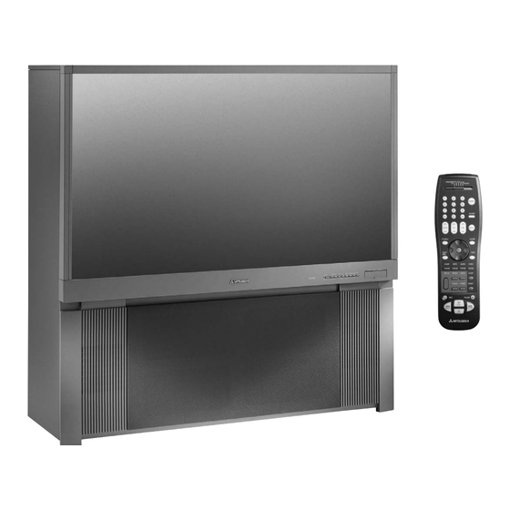
- Page 1 Owner’s Guide Projection Television Models WS-48513, WS-48613, WS-55513, WS-55613, WS-55813, WS-65513, WS-65613, WS-65713, WS-65813, WS-73513, WS-73713 visit our website at w w w. m i t s u b i s h i -t v.c o m...
- Page 2 CAUTION: To assure continued FCC compliance, the user must use a shielded video interface cable with bonded ferrite cores at both ends, when using the VGA or DVI input. Changes or modifications not expressly approved by Mitsubishi could void the user’s authority to operate this equipment.
-
Page 3: Table Of Contents
Audio/Video Surround Sound Receiver or Stereo System...21 DVD Player with Component Video ...22 Satellite Receiver with S-Video...22 External Digital TV (DTV or HDTV) Receiver ...23 MonitorLink™ with MonitorLink Control or DVI...25 Computer with a VGA Monitor...25 IR Emitter NetCommand® or IR Emitter Repeater ...25 Chapter 3 Basic Functions including NetCommand ®... -
Page 4: Important Safeguards
Do not block these openings or allow them to be obstructed by placing the TV on a bed, sofa, rug, or other similar surface. Nor should it be placed over a radiator or heat register. If the TV is to be placed in a rack or bookcase, ensure that there is adequate ventilation and that the manufacturer’s instructions... -
Page 5: Power Lines
Never push objects of any kind into this TV through openings as they may touch dangerous voltage points or short-out parts that could result in fire or electric shock. Never spill liquid of any kind on or into the TV. - Page 7 Chapter . . . Television Overview Thank you...8 Unpacking your New TV ...9 Special Features... 10 Front Control Panel ... 11 Back Panel ... 12 Important Notes ... 14...
-
Page 8: Thank You
The very core of our corporate philosophy is to provide our customers with the very best. Our development team at Mitsubishi has worked to provide you with a television that defines “state-of-the-art,” with the capability to meet your needs now and in the future. -
Page 9: Unpacking Your New Tv
® NetCommand Home Network Control System Your Mitsubishi bigscreen HDTV offers a new level of networking to combine selected older products with new and future digital products. NetCommand supports IEEE 1394 connections, HAVi (Home Audio Video Interoperability) Control system, Audio Video Control... -
Page 10: Front Control Panel
� � ����� � � ����� � ����� � � ����� � � ����� � CARD 2 SmartMedia CARD 1 MMC & SD IEEE 1394 CARD 3 CompactFlash CARD 4 M EMORY TICK ������� ����� �� ����� �� ������� IEEE 1394 WS-48613 WS-55613 WS-65613... -
Page 11: Front Control Panel
On from the Low Energy Mode, or using the SYSTEM RESET button, this light will flash rapidly for about one minute. Do not attempt to turn on the TV during this period. Wait for the flashing to stop before attempting to turn the TV on. -
Page 12: Back Panel
The left and right audio allow the external Mitsubishi HDTV Receiver/Controller or DVI set-top box to provide audio to the TV to be able to use the TV speakers. When MonitorLink is used as DVI, it is HDCP compatible. - Page 13 MonitorLink. While MonitorLink provides the digital video signal, MonitorLink Control provides enhanced functioning such as automatic power ON/OFF and input selection. If you are not connecting a Mitsubishi HDTV Receiver/Controller with MonitorLink features, MonitorLink Control can be used as an RS-232C control signal input port with an external control system.
-
Page 14: Important Notes
Mix the types of pictures shown. Uneven picture tube aging is NOT covered by your warranty. The normal use of a TV should include a mixture of TV picture types. The most frequently used picture types should fill the screen with constantly moving images rather than stationary images or patterns. - Page 15 Audio/Video Surround Sound Receiver or Stereo System ...21 DVD Player with Component Video Connections ...22 Satellite Receiver with S-Video...22 External Digital TV (DTV or HDTV) Receiver with Component Video ...23 with RGB,HV Video Connections...24 MonitorLink™ with MonitorLink Control or DVI ...25 Computer with a VGA Monitor Output ...25...
-
Page 16: External Devices And Netcommand Setup (Overview)
TV’s memory. NetCommand will also automatically switch the TV and compatible or learned Audio/Video (A/V) Receivers to the correct input used with each device. It is important that the inputs on the TV and A/V Receiver match the NetCommand Setup. -
Page 17: Netcommand Pre-Memorized Devices
Bright light near the TV screen can also adversely affect the learning feature. If it is not possible to learn a device, you will need to use the original remote control of the device, or program the TV remote to operate these devices in the traditional manner. -
Page 18: Antenna Or Wall Outlet Cable For Digital Broadcasts
1. Connect the UHF and VHF antenna leads to the UHF/ VHF combiner. 2. Push the combiner onto ANT-A on the TV back panel. Note: UHF/VHF combiners are not provided with the TV. They should be available at most electronic stores. -
Page 19: Single Analog Antenna, Wall Outlet Cable
1. Connect the incoming cable to ANT-A on the TV back panel. Note: Connect two coaxial cables as follows: 2. One from LOOP-OUT on the TV back panel to IN on the cable box back panel. 3. One from OUT on the cable box back panel to ANT-B on the TV back panel. -
Page 20: Analog Vcr
1. Connect the incoming cable to ANT-A on the TV back panel. Note: Connect three coaxial cables as follows: 2. One from LOOP-OUT on the TV back panel to IN on the back of the cable box. � 3. One from OUT on the back of the cable box to ANTENNA IN on the VCR back panel. -
Page 21: Analog Vcr With Composite Video Or S-Video And Audio Connections
Figure 8 1. Connect a set of audio cables from the Monitor OUTPUT AUDIO 2 on the back of the TV to the TV AUDIO INPUT on the back of the A/V Receiver. The red cable connects to the R (right) channel and the white cable connects to the L (left) channel. -
Page 22: Dvd Player With Component Video
Do not display the same stationary images on the screen for more than 15% of your total TV viewing in one week. Examples of stationary images are letterbox top/bottom bars from DVD or other video sources, side bars when showing standard TV pictures on widescreen TV’s, stock market reports, video game patterns, station logos, black or bright Closed caption backgrounds, web sites or stationary computer images. -
Page 23: External Digital Tv (Dtv Or Hdtv) Receiver
Connecting an External Digital TV (DTV or HDTV) Receiver DTV Connectors and Adaptors Figure 11 The TV back panel has 5 RCA-type connectors for the Input-DTV. The back panel of your external DTV receiver may use RCA-type connectors or BNC-type connectors. -
Page 24: With Rgb,Hv Video Connections
Connecting an External Digital TV (DTV or HDTV) Receiver with RGB, HV Video Connections It may be necessary to obtain a VGA to RGB audio adaptor cable. These are available at most computer stores and many electronic stores. Some of the adaptor cables have RCA type connector ends, others have BNC type ends and will require adaptors as shown on page 21. -
Page 25: Monitorlink™ With Monitorlink Control Or Dvi
Connecting MonitorLink™ with MonitorLink Control or DVI MonitorLink and MonitorLink Control Figure 14 1. Connect a MonitorLink cable from the Mitsubishi Receiver/Controller back panel to the TV back panel. 2. Connect the L (left) and R (right) audio cables from... -
Page 26: Ir Emitter Netcommand® Or Ir Emitter Repeater
The emitters connected to these jacks are not used by NetCommand, but will repeat any IR command received by the TV. These emitters allow the TV to be the remote control sensor for other devices outside the range of the hand-held remote control. - Page 27 Basic Functions including NetCommand Editing Remote Control Functions: Overview ...28 Remote Control Functions: Operation and Care ...29 Programming the Remote Control to Control NetCommand A/V Products ...30 3D Graphical Viewpoint Menu System...31 Using the Remote Control with NetCommand® Setup...32 NetCommand Initial Setup Guide ...33 NetCommand Editing Guide ...34 NetCommand Initial Setup ...35 Edit NetCommand...
-
Page 28: Remote Control Functions: Overview
23. EXCH: Exchange PIP or POP and main TV picture. 24. SLEEP: Set the TV to turn off within 2 hours. See Sleep Timer for setup instructions. 25. PIP DEVICE: Displays PIP Selection menu to select the PIP or POP image source device. -
Page 29: Remote Control Functions:operation And Care
Remote Control Functions:Operation and Care CABLE/DBS/DTV AUDIO DEVICE TVMENU DEVI C E MENU V-CHIP AUDIO INFO EXCH PIP CH PIP/POP PIP DEVICE FORMAT PAUSE PLAY REW/REV STOP Figure 1. Remote Control Overview Operation Figure 2 Installing the Batteries: 1. Remove the remote control’s back cover by gently pressing the ribbed tab in the direction of the arrow and sliding off the cover. -
Page 30: Programming The Remote Control To Control Netcommand A/V Products
3. Enter the three digit code of 935, and then release the POWER button on the remote control. 4. The remote control is now programmed to send NetCommand signals to the TV so the TV can control the IEEE 1394 devices and older NetCommand supported or learned IR devices, while the slide switch is in the TV position. -
Page 31: Graphical Viewpoint Menu System
Your TV has a special control system called NetCommand devices. For instructions on operating these control features, see the next page. Your TV also has Mitsubishi’s exclusive 3D Graphical on-screen operating system, which provides on-screen information for menu choices and changes, using the TV’s remote control. -
Page 32: Using The Remote Control With Netcommand® Setup
In order to use the TV’s NetCommand feature, you need to provide some detailed information during the setup of your Mitsubishi TV. You must define the Manufacturer of the devices that are connected to the television, or learn the IR code remote control signals for the device connected. -
Page 33: Netcommand Initial Setup Guide
You will find detailed information regarding each screen in the pages following this Guide. Initial Initial NetCommand Setup: When you first turn on your TV. You may Cancel at any screen. Language Screen Page 35 Figure 1... -
Page 34: Netcommand Editing Guide
(See Learning Instructions for details) Name screen (select name for the device) Page 39 Figure 10 Monitor Out to AVR screen (select TV monitor output that is connected to AVR and AVR input used) Page 39 Figure 11 Change New Device screen... -
Page 35: Netcommand Initial Setup
Initial Setup ® When you first power On your new Mitsubishi TV, the initial setup screens appear. In order to use NetCommand, select these screens after you have connected the compatible equipment to the TV. Most IR remote control signal formats can be learned by NetCommand. - Page 36 On the Review Screen, adding or deleting check marks will turn the adjacent devices, memory cards or inputs On or Off. If 1394 devices are not connected to the TV, the 1394 Name list will not appear on the Review screen.
-
Page 37: Edit Netcommand
NetCommand will display at the bottom of the screen. If a number follows the manufacturer’s name, (example: Mitsubishi 1), this indicates additional models are optimized for that manufacturer. For many device types, non-listed models will operate in the same way as the listed models and you can still use the pre-loaded setting. - Page 38 This confirms the signal learned status. 4. To test the learned command, press ENT(er) on the TV remote. The A/V Receiver will perform the selected function. The A/V Receiver needs to be turned on and the IR emitters properly placed for the test to be successful (see page 26 for IR emitter placement).
- Page 39 Figure 11 Use this screen if you connected Audio 2 Out or Audio Video 1 Out from Monitor Output of the TV to the A/V Receiver. Select “Audio 2” or “Audio Video 1” on this screen and then select the input on the A/V Receiver connected to Monitor Out.
-
Page 40: Adding Devices
Edit NetCommand Mitsubishi’s NetCommand offers the ability to edit your home theater configuration so that you can add new devices, change device settings and connection inputs, delete devices and even learn the remote control IR signals of devices that are not already in the NetCommand memory. - Page 41 NetCommand will display at the bottom of the screen. If a number follows the manufacturer’s name, (example: Mitsubishi 1), this indicates additional models are optimized for that manufacturer. For many device types, non-listed models will operate in the same way as the listed models and you can still use the pre-loaded setting.
- Page 42 Figure 19 This screen allows you to match the device names with the inputs that were connected to the TV in Chapter 2. Inputs 1-3, Components 1 & 2, Input-DTV and/or the A/V Receiver all need to be checked, if connected. Add or remove check marks to indicate what type of connections (Audio, Video or Both) are used with each input.
- Page 43 IR code as a previously added device of the same type and manufacturer. You can specify the IR setting for the new device. For example, for the second Mitsubishi VCR you can specify the IR Code setting to VCR-B, if the primary Mitsubishi VCR is using the VCR-A IR code.
-
Page 44: Changing, Deleting Devices
Change screen. To change a device, select the device by name, not type. You can change the name or input connections to the TV and A/V Receiver. If “Other” is selected for the manufacturer then you can also “Learn”. -
Page 45: Connecting Ieee 1394 Devices
6 pin to 4 pin adaptor computer stores. If you connect a 6-pin device to the TV (such as a camcorder) that is designed to receive electrical power from another 6-pin device, then you will need to connect the camcorder directly to the household AC, or use the camcorder’s battery for power. -
Page 46: Adding Ieee 1394 Devices Automatically
Connecting IEEE 1394 Devices, continued When Connecting IEEE 1394 Devices • Do not loop the last device in the chain back to the TV. When the device chain is looped, the TV may not be able to work with the other devices. -
Page 47: Adding Ieee 1394 Devices Automatically
VCR. For example, if the IEEE 1394 device you have added is a Mitsubishi D-VHS VCR, and you have selected an analog connection as a second connection, then you will select Mitsubishi for the manufacturer. - Page 48 Adding IEEE 1394 Devices Automatically, continued Compatible IEEE 1394 Devices It is possible to connect devices to the TV that have IEEE 1394 connectors but are not compatible with the TV or with ® the NetCommand control system. Areas of compatibility to consider are: 1.
- Page 49 Chapter . . . Device Selection Device Selection Menu ...50 PIP Device Selection Menu ...51 Transport Menu ...51 Channel Selection, Sleep Timer, Audio and Video Buttons...52 NetCommand Controlled Recordings...53...
-
Page 50: Device Selection Menu
NetCommand® has not been setup, the Device Selection menu allows you to select an input for viewing. When NetCommand is setup the Device Selection menu allows you to select the device for viewing, select audio from the TV speakers or A/V Receiver, power compatible devices On or Off, and verify the destination of signals. -
Page 51: Pip Device Selection Menu
You can turn off the automatic display of the transport menu in the Setup menu of the TV. The Setup menu is explained in the next chapter. When turned off, the transport menu will not be displayed when you select VCR or DVD Player on the Device Selection menu, or press a transport button, or DEVICE MENU. -
Page 52: Channel Selection, Sleep Timer, Audio And Video Buttons
1. Press SLEEP on the remote control. Note: A message indicating the length of time the sleep timer is to be set for is displayed on the TV screen. 2. Each press of SLEEP increases the time displayed by 30 minutes, until the maximum value of 120 minutes is reached. -
Page 53: Netcommand Controlled Recordings
Audio Video 1 of Monitor Output. During the analog recording, the TV can be powered Off. If the TV is powered On, it must be tuned to the source that is being recorded. If the Monitor outputs are sent through the A/V Receiver to a recording device, then the A/V Receiver must be turned on and set to the TV input. - Page 54 NetCommand will change the tag to “Record No More”. Restrictions for Traditional VCRs If turned On, the TV must be tuned to the source device. • Either your VCR must be connected directly to Audio Video 1 or, if the A/V Receiver is connected to Audio Video 1, then the VCR must be connected to the record outputs on the A/V Receiver.
- Page 55 Chapter . . . TV Menu Screen Operations Main Menu Choices ...56 Setup Menu ...57 Antenna Menu...58 Time Menu...60 Captions Menu...62 V-Chip Lock Menu ...64 A/V Settings Menu ...67 A/V Settings Descriptions ...68 Advanced Menu: Convergence ...70 Important Notes ...72...
-
Page 56: Main Menu Choices
Figure 2. Main menu, Antenna selected Time Figure 3 Manually set the time for the TV, or select Auto and the TV will automatically set the time based upon Extended Data Service (XDS) time data. This time data is usually broadcast by your local PBS station. -
Page 57: Setup Menu
• IEEE 1394 functions that pass through the TV or IEEE 1394 recordings from the TV or Ant-DTV will not be possible. • The amount of time required to turn on the TV will increase to more than one minute. -
Page 58: Antenna Menu
Name Channels shown on Antenna A or Antenna B can be named (up to four characters). After you enter a name, it will appear on the TV screen, next to the channel number. 1. Press ADJUST to select each letter. - Page 59 Once you have added a channel to an SQV memory, “SQV” and the memory bank number will appear under the tuned channel number on the TV screen. Adding SQV Channels 1. Select the channel using the “Channel” option box or press CH 2.
-
Page 60: Time Menu
This data is automatically retrieved from a PBS channel or other channel carrying this service when received on Ant-A or Ant-B. Be aware that some channels may send incorrect time information, this is not a defect in the TV. Figure 12. Time Menu, Auto Clock Setting Time Zone When Auto has been selected for the Clock Setting, you need to select the correct time zone. -
Page 61: Set Time
Device Press ADJUST the timer turns on the TV. If the TV is already on, the timer will turn the TV to this selected device. Channel When Antenna A, Antenna B, or Antenna DTV is the selected device, you may select any memorized channel. -
Page 62: Captions Menu
If you use Closed Captions frequently, Mitsubishi recommends gray for the background to reduce uneven aging of the picture tubes. Note: See page 72 for information concerning uneven aging of picture tubes. -
Page 63: Background Opacity
• Transparent - See-through text to the TV program • Translucent - TV program is visible behind the text • Opaque - Solid color text; blocks the TV program • Flashing - Text flashing in intervals Background Opacity You can customize the background for digital captions using the following categories: •... -
Page 64: V-Chip Lock Menu
V-CHIP button on the remote control to conveniently turn the V-CHIP on or off. The factory preset is TV-PG for TV ratings or PG for movie ratings, allowing only programs rated TV-PG/PG or lower. You can change the blocking level to various TV ratings and lettered categories or movie ratings. - Page 65 As an example, if you select to block V (Violence) at the TV-14 level, you will also block any program that has the V category listing at the TV-PG rating level as well.
- Page 66 8 seconds. If the TV is already on, a message will be displayed to confirm the release of the Front Button Lock. If the TV is in Low Energy mode, to restore the function of the front panel buttons, press Power on the front panel.
-
Page 67: A/V Settings Menu
The contrast in dark scenes is enhanced for better picture quality. Brighter scenes will not be affected. TV Speakers This selection will turn on or off the TV’s internal speakers. You may select Off when sending the sound through a separate stereo system or surround sound A/V receiver. -
Page 68: A/V Settings Descriptions
When connecting to an A/V Receiver, set level sound to OFF and turn the TV speakers off to send full dynamics to the A/V Receiver. This feature only works with Dolby Digital sources. -
Page 69: Video Settings
On setting will automatically apply video decoding, the same as used with the Off setting. Try the Off setting when the TV seems to have difficulties and adds too many jagged edges to the images. -
Page 70: Advanced Menu: Reset Factory Defaults, Convergence
Select Advanced to perform the functions listed below. Figure 22. Advanced Menu, Convergence Your Mitsubishi TV has three picture tubes which need to be aligned to properly converge the projected light beams on the screen. Each picture tube projects a single color of red, blue or green. -
Page 71: Auto Color Correction
Color Balance Figure 26 Your Mitsubishi TV uses six colors (Magenta, Red, Yellow, Green, Cyan and Blue) to create color balance. You may adjust the intensity of the colors automatically or manually (PerfectColor™) or reset them to the default settings. -
Page 72: Important Notes
On-line (Internet) web sites: or any other stationary or repetitive computer style images. Closed Caption Backgrounds: When set to black or bright color, if Close Caption will be used frequently, Mitsubishi suggests the use of the gray background. - Page 73 Chapter . . . Special Features NetCommand Controlled Peer-to-Peer Connections ...74 NetCommand Remote Control Buttons Device Menu, Guide ...75 Recording on a NetCommand Traditional VCR, A/V Disc Search, Track List Screen...76 Memory Card Playback ...77 Device Menu with NetCommand ...79 Operation of PIP and POP ...81 Display Formats ...82 Note on Software Updates ...84...
-
Page 74: Netcommand Controlled Peer-To-Peer Connections
Recording from Ant-DTV to a DVCR is also a peer-to-peer connection. In this case the TV is one of the devices in the peer-to peer connection. Analog or traditional (non-digital) devices can not be used for peer-to-peer connections. -
Page 75: Netcommand Remote Control Buttons: Device Menu, Guide
• For IEEE 1394 devices with digital connections, the first press and ENT(er). For of GUIDE will display the TV’s digital channel guide. The second press will display the program guide for the tuned device, such as a cable box or DBS. -
Page 76: Recording On A Net Command® Traditional Vcr, A/V Disc Search, Track List Screen
VCR’s remote control or front panel. To record directly from antenna or cable: 1. Press DEVICE on the TV’s remote to display the Device Selection menu. Highlight the traditional VCR and press POWER to turn on the VCR. If necessary, press GUIDE to select the input the VCR is on, such as Antenna input (or line input). -
Page 77: Memory Card Playback
Inserting a Memory Card 1. Insert a card into a matching card slot on the front of the TV. Be sure to use the correct card slot. Card 1 will accept MultiMediaCard™ and SD Memory Card. Card 2 will accept SmartMedia™. Card 3 will accept CompactFlash®. - Page 78 HOME to exit. Figure 6. Media Setup Menu IMPORTANT JPEG images cannot be edited through the TV. Only name changes should be made on your PC to avoid file incompatibility problems. MP3’s must have at least 32 KHz sampling rate.
-
Page 79: Device Menu With Netcommand
Device Menu with Net Command NetCommand Compatible Traditional Devices (Analog) When Device Selection Menu is Displayed and the Device is Highlighted (Yellow Outline) REMOTE A/VReceiver CONTROL BUTTON POWER Power On/Off (toggle) DEVICE MENU GUIDE Changes between Digital and Analog audio FORMAT IEEE 1394 and HAVi Devices (Digital) When Device Selection Menu is Displayed and the Device is Highlighted (Yellow Outline) - Page 80 Device Menu with Net Command When Net Command® Compatible Traditional Device is Viewed or Played Remote Control Receiver Button CH up/down Channel up/down VOL up/down Volume Up/Down MUTE Mute On/Off 0-9 (digits) number functions DEVICE Menu 1st press Transport Menu, 2nd press Setup Menu display HOME ENTer...
-
Page 81: Operation Of Pip And Pop
POPs Activating the PIP and POP Press PIP/POP to activate the PIP/POP option. With each press of the PIP/POP button on the TV remote control (within 3 seconds of each other), the PIP/POP will cycle through the following display options:... -
Page 82: Display Formats
(called 4:3 aspect ratio) you will encounter. While there will never be a perfect solution for displaying a narrow image on a wide screen, Mitsubishi offers several display formats to choose from. Press FORMAT on the TV remote control to cycle through the available display formats. - Page 83 Display Formats �������� ������ �������������� �� ������� ��� �� ������� �������� ���� ������������ ���������� ������ ������������ ��� ������������ ���� ��� ��������� ��� ������� �� ��� ���� ������������ ���������� ��������� ��� ��������� ��� ������� �� ��� ������������ ��� �������� ���������� ��������� ���� ���...
-
Page 84: Software Updates
Software Updates From time to time, Mitsubishi may offer software updates to expand the features or operation of this TV. When these updates are available they will be announced on our web site, Mitsubishi-tv.com. If you return your Owner’s registration card, with your model and serial number, you may receive written notification of available software updates. -
Page 85: Appendixes
If you forget your passcode, you can view the locked TV without entering your passcode. This is done by pressing the number 9 and QV buttons on the TV remote control at the same time, when your passcode is requested. This process temporarily unlocks the TV. - Page 86 This page intentionally blank...
-
Page 87: Vga Input
This exciting new networking and control technology is designed to provide high-performance digital connections and product control, making products easier to use. At the time of development,the only products available for compatibility testing - the Mitsubishi and JVC DVHS VCRs. These D-VHS VCRs are fully compatible with this TV. -
Page 88: Appendix C:remote Control Programming Codes
If the equipment does not respond, repeat steps 2-4 with the next three digit code listed in step 3 for your equipment. A/V Receivers Mitsubishi 010, 011, 012, 013, 014, 360 Admiral... - Page 89 Appendix C: Remote Control Programming Codes DVD Players Mitsubishi Aiwa 261, 274 Apex 266, 283 Bose Denon 250, 273 Ferguson GE/RCA/Proscan 251, 256 Harman Kardon 282, 288 Hitachi Kenwood 271, 289 Mintek Next Base Normande Onkyo 267, 280 Oritron 263, 268...
- Page 90 A/V Receiver chart while the slide switch is set to TV, the volume and mute functions change to match the A/V receiver. This is useful when using an A/V Receiver with the TV all the time. In all other cases, only one of the below devices is allowed for each slide switch position.
- Page 91 Appendix C: Remote Control Programming Codes When your remote control has been programmed to operate another manufacturer’s product, the function performed on each layer can vary. The most common functions are: � � � � ��� � � ��� � ����� � �...
-
Page 92: Appendix D: On-Screen Information Displays
Appendix D: On Screen Information Displays When you turn on the TV, change Devices, change Channels or when you press the INFO button on the remote control the TV will display the current status. Below are the most common displays; please note that seldom or never do all of the different status indicators appear at the same time. -
Page 93: Appendix E: Netcommand® Specialized Device Keys
Hi Speed 480p/1080i out 1,2,3,4,5,6,7,8,9,0 1,2,3,4,5,6,7,8,9,0 Input Input Change Sub channel separator‡ Digital Sub channel Chapter + Chapter Skip Forward Chapter - Chapter Skip Reverse Name on TV Remote POWER** POWER** MUTE GUIDE** GUIDE** Automatic (when device is selected) CHAN CHAN GUIDE... -
Page 94: Appendix F: Cleaning And Service
Diamond Shield™. Service If you are unable to correct a problem with your TV, consult your Mitsubishi dealer or a Mitsubishi Authorized Warranty Service Center. • DO NOT adjust any controls other than those described in this Owner’s Guide. -
Page 95: Appendix G: Diamond Shield™ Removal
Appendix G: Diamond Shield™ Removal for Models WS-48513, WS-48613, WS-55513, WS-55613, WS-65513, WS-65613 and WS-73513 The instructions below will lead you through the Diamond Shield removal process for models WS-48513, WS-48613, WS-55513, WS-55613, WS-65513, WS-65613 and WS-73513. The Diamond Shield for these models comes installed by the factory. -
Page 96: Diamond Shield Installation
Appendix G: Diamond Shield™ Installation for Models WS-55813, WS-65713, WS-65813 and WS-73713 The instructions below will lead you through the Diamond Shield installation process. Included in the Diamond Shield package are the following items: For models WS-55813, WS-65713, WS-65813 and WS-73713 (1) Diamond Shield™... -
Page 97: Appendix H: Cabinet Separation
Appendix H: Cabinet Separation for Models WS-65513, WS-65613 ��� ���������� ������� ��� ������� ��������� ���� ��� �������� ��� ���������� ���������� ���������� ������ �������� ��� �������� ���� ���� ��������� �� ��� ������� ����� ������ ��� �� ��������� �� ����� ��� ������ �������� ��� ������ ��� ������������ ����� ����... - Page 98 WS-73513, WS-73713 For Mitsubishi Dealers and Service Personnel Only The Mitsubishi TV models WS-65713, WS-73513 and WS-73713 cabinets are assembled in two pieces. These pieces may be separated to allow for easier delivery and set up. The instructions below show how to safely separate and reattach the cabinet.
- Page 99 Appendix H: Cabinet Separation for Model WS-65813 ��� ���������� ������� ��� ������� ��������� ���� ��� ���������� �� ����� �������� ���������� ���������� ������� ��� ���� ��������� �� ��� ������� ����� ������ ��� �� ��������� �� ����� ��� ������ �������� ��� ������ ��� ������������ ����� ���� ��� �� ������ ��������...
-
Page 100: Troubleshooting
• Room lighting may affect the signal. Have the remotes very close (6 inches or less) to the TV during Learning. • If using a Mitsubishi remote control make sure slide switch is not set to TV position. • Some but not all device key functions can be learned by NetCommand. - Page 101 • Digital devices (Ant-DTV ,1394 devices and Memory cards) cannot display in the PIP or POP. • The A/V Receiver is not connected to any input of the TV. To check the A/V Receiver menu temporarily plug into an unused input of the TV.
- Page 102 • The device is already in use (for example: the device is currently recording). • The source is copy-protected or violates copy protection. • The device’s digital video signal is not supported by the TV, such as DV video, common with camcorders. Use analog connections instead, if available.
-
Page 103: Using The System Reset Button
The TV will turn off and the green led will flash quickly for about one minute. When the green led stops flashing, you may turn on the TV again. The changes you made while the TV was most recently on, before you used the SYSTEM RESET button may lost, however, the changes you made previously are not lost. -
Page 104: Index
Index A/V (Audio Video) Memory Reset 67 Receiver, Connecting 21 A/V Disc Search 76 A/V Receiver Connecting 21 with NetCommand 37-39 Advanced Menu 56, 70-71 Advanced Convergence 71 Convergence 70 Reset Factory Defaults 70 Antenna Menu 56, 58-59 Appendixes A: Bypassing the V-Chip Lock 85 B: High Definition Input Connection Compatibility 87 C: Remote Control Programming Codes 88-91 D: On Screen Information Displays 92... - Page 105 Time Zone Setting 60 Timer, Setting the 61 Track List 76 Transport Menu 51, 57 Troubleshooting 100-103 TV Speakers Selection 67 V-Chip Lock Menu 56, 64-66 Front Button Lock 66 Lock by Time 66 Passcode 64, 85 Start, Stop Time, 64...
- Page 106 Demo Mode This TV has a demo mode for use in a retail store. To turn On/Off, press the following buttons in sequence: MENU, 0, QV, 0 LICENSOR’S SUPPLIERS DO NOT MAKE OR PASS ON TO END USER OR ANY OTHER THIRD PARTY, ANY EXPRESS,...
-
Page 107: Warranty
MITSUBISHI service center; physical abuse to or misuse of the product (including any failure to carry out any maintenance as described in the Owner’s Guide or any product damaged by excessive physical or electrical stress);... -
Page 108: Mitsubishi Tv Software
ABOVE LIMITATIONS MAY NOT APPLY TO YOU. MDEA’s liability to you for direct damages for any cause whatsoever and regardless of the form of the action, will be limited to the money paid by you for the TV (based on fair market value of the TV) that caused the damages. - Page 109 NetCommand system to use the TV outputs to transfer the device’s audio to the A/V Receiver. See Edit NetCommand Setup. 2. Use RCA type “Y” splitter cables to split the device’s audio output to be connected to both the TV and the A/V Receiver.
- Page 110 To order replacement or additional remote controls or owner’s guides call (800) 553-7278 visit our website at w w w.m i t s u b i s h i -t v.c o m © 2003 Mitsubishi Digital Electronics America, Inc. Written and Printed in the U.S.A 871D370B10...