Advertisement
Quick Links
Published Manual Number/ECN: ME6PM1S1AE/2015352A
• Publishing System: TPAS2
• Access date: 08/24/2015
• Document ECNs: Latest
Schematic/Electrical Parts
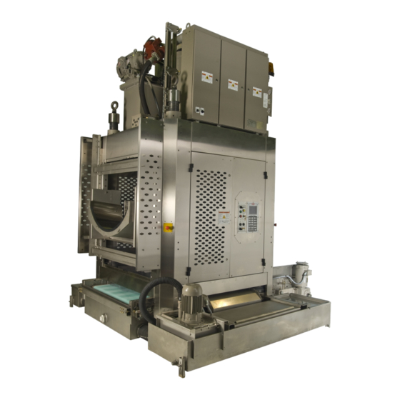
SINGLE STAGE PRESS
MP1540, MP1550, MP1601,
MP1602, MP1603, MP1604,
MP1650, MP1A50, and MP1A03
PELLERIN MILNOR CORPORATION
POST OFFICE BOX 400, KENNER, LOUISIANA 70063-0400, U.S.A.
Advertisement

Related Manuals for Milnor MP1550


Summary of Contents for Milnor MP1550
- Page 1 Published Manual Number/ECN: ME6PM1S1AE/2015352A • Publishing System: TPAS2 • Access date: 08/24/2015 • Document ECNs: Latest Schematic/Electrical Parts SINGLE STAGE PRESS MP1540, MP1550, MP1601, MP1602, MP1603, MP1604, MP1650, MP1A50, and MP1A03 PELLERIN MILNOR CORPORATION POST OFFICE BOX 400, KENNER, LOUISIANA 70063-0400, U.S.A.
- Page 3 Document Component Parts List W6PM1SPL/2015184N Limited Standard Warranty BMP720097/2008272A How to Get the Necessary Repair Components BIUUUD19/20081231 Milnor Allied Interface Specifications and Signals, Single Stage Press BICALC02P1/20031016 How to Use Milnor® Electrical Schematic Diagrams BIUUUK01/20130308 Sample Schematic BMP010012/2001503N Wiring Safety Fence Gate Interlocks...
- Page 4 Table of Contents, continued ME6PM1S1AE/15352A Page Description Document Soft Squeeze W6PM1SSQ/2011452B Electrical Valves MkV only W6PM1SVS/2014252B Electrical Valves Mk VI - Spray Ring W6PM1SVSA/2014252B Electrical Valves Mk VI - Soft Squeeze W6PM1SVSB/2014252B...
- Page 13 (unless the time period is specifically extended for certain parts pursuant to a specific MILNOR published extended warranty) from our factory with no operating hour limitation. This warranty is contingent upon the equipment being installed, operated and serviced as specified in the operating manual supplied with the equipment, and operated under normal conditions by competent operators.
- Page 14 • If the component is an electrical component, give the schematic number if known. • If the component is a motor or an electrical control, give the nameplate data from the used component. To write to the Milnor factory: Pellerin Milnor Corporation Post Office Box 400...
- Page 15 Interface Specifications and Signals, Single Stage Press An allied device that interfaces with the Milnor system machine equipped with Mark 5 or later microprocessor controls must meet the electrical specifications and functional requirements given in Section 1 “Electrical and Functional Specifications”.
- Page 16 Functional Requirements 1.3. 1. For numeric signals (batch codes) from allied to Milnor (allied loading interface), all signals must be properly set when the operational signal indicating this data is valid occurs. Signals must remain set for the longer of 5 seconds or through any subsequent operational signal requiring this data (see “Loading Interface non-Numeric Signals...”).
- Page 17 In an allied loading interface, all numeric signals pass from allied to Milnor and are therefore, inputs to Milnor. 2. Loading interface non-numeric signals and enabling order—In this table, each row represents a signal and each column provides pertinent information for that signal.
- Page 18 Output* 312* o1/j o1/1 load allowed / press free Milnor will read in all batch data (previous table and next three signals) when it receives the "transfer complete / press loaded" signal. Input i1/i io1/8 new customer Input...
- Page 19 * For outputs from Milnor, Milnor does not normally assign either pin of the potential-free contact as the common. Hence, both pins have unique pin and wire numbers. In this table these are listed together in the same cell, with a dot between (e.g., C • D) **To provide eight customer code signals with limited available terminals, Customer codes A through H had to share pin 1.
- Page 20 H = This input is represented by the character “H” on the display. Note 4: When the Milnor Dryer/Shuttle Controller is provided for a new installation, the LCD displays are omitted from the controllers for any shuttle(s) and dryer(s) also provided. In this case, inputs and outputs may be viewed on the monitor supplied with the shuttle/dryer controller.
- Page 21 This table's columns correspond to, and align with the columns in each table of numeric signals herein. For higher numbers, use the “Decimal Value of Signal” values in this table to convert between decimal and binary as explained herein. PELLERIN MILNOR CORPORATION...
- Page 22 602 to binary, use the “Decimal value of binary 1 in this position” values, as follows: 512 = highest value not exceeding 602. 602 – 512 = 90 64 = highest value not exceeding 90. 90 – 64 = 26 16 = highest value not exceeding 26. 26 – 16 = 10 PELLERIN MILNOR CORPORATION...
- Page 23 (zero) in any position has the decimal value 0 (zero). The conversion for binary 1001011010 looks like this: 512 + 0 + 0 + 64 + 0 + 16 + 8 + 0 + 2 + 0 = 602 Hence, binary 1001011010 = decimal 602. — End of BICALC02 — PELLERIN MILNOR CORPORATION...
- Page 24 “SR” stands for safety reset. Thus, CDSR is a time delay relay that serves as a safety reset. ® The following are descriptions of electrical components used in Milnor machines. Descriptions are in alphabetical order by the component class code (two character prefix).
- Page 25 ® How to Use Milnor Electrical Schematic Diagrams Figure 2: Time Delay Relay (CD) Coil and Contacts Legend Coil Contacts CL=Control, Latch Relay (Figure 3)—A relay which latches in an energized or set position when operated by one coil (the latch/set coil). The relay stays latched even though coil voltage is removed.
- Page 26 ® How to Use Milnor Electrical Schematic Diagrams Figure 5: Photo-eye (CP) Symbols Legend Example of single assembly Example of two separate assemblies CS=Control, Contactor/Motor Starter (Figure 6)—A relay capable of handling heavier electrical loads, usually a motor. Figure 6: Other Control Symbols...
- Page 27 ® How to Use Milnor Electrical Schematic Diagrams Figure 7: Thermal Overload (ET) Schematic Symbol Legend Heater (one per phase) Overload relay; contacts open if overload condition exists EX=Electrical Transformer (Figure 8)—A device that transfers electrical energy from one isolated circuit to another, often raising or lowering the voltage in the process.
- Page 28 ® How to Use Milnor Electrical Schematic Diagrams Figure 10: Proximity Switches (PX) Switch Symbols Legend Alternating current proximity switch Direct current proximity switch SC=Switch, Cam Operated (Figure 11)—A switch in which the electrical contacts are opened and/or closed by the mechanical action of a cam(s). Applications include 35-50 pound timer operated machines, Autospot, timer reversing motor assembly, and some balancing systems.
- Page 29 ® How to Use Milnor Electrical Schematic Diagrams Figure 15: Mechanical Switch (SM) Figure 16: Pressure Switch (SP) ST=Switch, Temperature Operated (Figure 17)—A switch that is actuated at a preset temperature (e.g., dryer safety probes) or has adjustable set points (e.g., Motometers or Combistats).
- Page 30 Milnor machines often do not correspond to the pin numbers shown in the schematics. • Ignore pin numbers imprinted on in-line connectors (e.g., Molex connectors) and relay bases.
- Page 31 ® How to Use Milnor Electrical Schematic Diagrams Figure 22: Plug-in Relays 11-pin Relay with Grey Base Legend Left. View of relay base Right. Same view, show- ing pin num- bers 14-pin Relay with Grey Base (older) 14-pin Relay with Black Base (newer)
- Page 32 ® How to Use Milnor Electrical Schematic Diagrams Note 3: Relay functional names ending with the letter "M" (e.g., CRxxM) are not discrete components but are a component of a printed circuit board. They are usually not individually replaceable. Figure 23: AMP Connector Pin Locations...
- Page 33 ® How to Use Milnor Electrical Schematic Diagrams Figure 24: Molex Connector Pin Locations 15-pin Connector 9-pin Connector 6-pin Connector 4-Pin Connector 2-pin Connector Legend View of mating halves of connector Same view, showing assigned pin numbers PELLERIN MILNOR CORPORATION...
- Page 34 ® How to Use Milnor Electrical Schematic Diagrams Figure 25: Pressure Switch Component Legend Contact 1—Normally open Contact 2—Normally closed Contact 3—Common Figure 26: Toggle Switch Component Legend Normally closed contacts Common contacts Normally open contacts Pole Figure 27: Switch with Replaceable Contact Blocks...
- Page 35 3. Line numbers are provided along the bottom edge of the drawing. These permit service ® personnel in the field and at the Milnor factory to quickly relate circuit locations when discussing troubleshooting over the phone. Page and line numbers are referenced on the drawing as explained in items five and six below.
- Page 36 This indicates on which page (W6DRYGS+) and line number (08) the relay coil can be found for this set of contacts Any relay that ends with an "M" is located on an electronic board. This indicates on which schematic page and line number the relay contacts of this coil (on Line 08) are located (i.e.,...
- Page 37 Mass termination assembly Pin number 1MTA5-9 MTA designation on board Board MTA group designation An MTA is a connection on an electronic circuit board. The notes and the tag page locate the appropriate board. Major revision (letter) Page number (S+) Machine type (Gas fired dryer) Wire identification marking.
- Page 38 This document is to be used in conjunction with Milnor document W6SYSSG “Micro 6 Systems Schematic: Customer-Provided Safety Fence Gate Interlock”. Together, these documents describe how to connect a customer-provided gate switch or series of switches to any Milnor shuttle, press, or centrifugal extractor. Another Milnor document—BISUUI01 “Proximity Safeguarding for Automatic Shuttle Conveyors”—discusses the general hazards that safety fencing addresses.
- Page 39 ® Wiring Safety Fence Gate Interlocks on Milnor Shuttles, Presses and Centrifugal Extractors Testing Once wiring is completed, it is vital to test the system to ensure that: 1. all gate interlocks function properly, and 2. all components that were part of the machine's three-wire circuit before the gate interlocks were added continue to function properly.
- Page 44 W6PM1STG1 2012235B...
- Page 45 COINC ONLY INCOMING AIR ALL VALVES ARE N/C UNLESS OTHER WISE NOTED MICRO 6 SYSTEMS SINGLE STAGE PRESS AIR VALVE BOX PELLERIN MILNOR CORPORATION B2TAG98011 2005342G OPTIONAL FOR PIVOTING COINIC 1MTM1 SNUBBER CSHP CRGC CRFLH CRFLL CRPRB CD1 BOARD HYDRAULIC...