Sharp UX-P410 Service Manual
Hide thumbs
Also See for UX-P410:
- Operation manual (87 pages) ,
- User manual (91 pages) ,
- Operation manual (291 pages)
Table of Contents
Advertisement
Quick Links
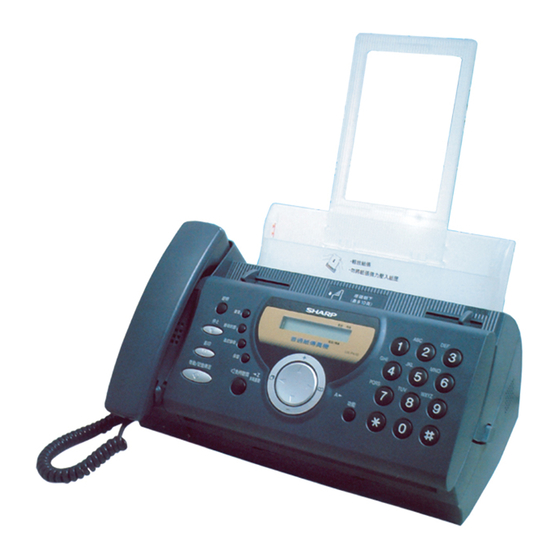
Illustration: UX-P410TH
[1] Specifications ............................................ 1-1
[2] Operation panel ......................................... 1-2
[3] Transmittable documents .......................... 1-3
[4] Installation ................................................. 1-4
[5] Quick reference guide ............................... 1-8
[6] Option imaging film specifications ..............1-8
[1] Adjustments ............................................... 2-1
[2] Diagnostics and service soft switch .......... 2-2
[3] Troubleshooting ....................................... 2-19
[4] Error code table ....................................... 2-20
[1] General description ................................... 3-1
[2] Disassembly and assembly
procedures ....................................... 3-3
[1] Block diagram ............................................4-1
[2] Wiring diagram .......................................... 4-2
[3] Point-to-point diagram ............................... 4-3
Parts marked with "
" are important for maintaining the safety of the set. Be sure to replace these parts with specified ones for
maintaining the safety and performance of the set.
SERVICE MANUAL
CONTENTS
SHARP CORPORATION
UX-P410TH/FO-P610TH/NX-P160TH
No. 00ZUP410THSME
FACSIMILE
MODEL
MODEL
SELECTION CODE DESTINATION
UX-P410
FO-P610
NX-P160
[1] Circuit description ...................................... 5-1
[2] Circuit description of control PWB ..............5-2
[3] Circuit description of TEL/LIU PWB .......... 5-9
power supply PWB ............................5-12
[5] Circuit description of CIS unit ...................5-12
[1] Control PWB circuit ................................... 6-1
[2] TEL/LIU PWB circuit ................................. 6-9
[3] Power supply PWB circuit ...................... 6-14
[4] Operation panel PWB circuit ................... 6-16
[1] Protocol ..................................................... 7-1
[2] Power on sequence .................................. 7-2
[1] Service tools .............................................. 8-1
[2] IC signal name .......................................... 8-4
[3] Rewriting version up the FLASH ROM .......8-4
This document has been published to be used
for after sales service only.
The contents are subject to change without notice.
UX-P410
FO-P610
NX-P160
TH
Thailand
TH
Thailand
TH
Thailand
Advertisement
Table of Contents

Related Manuals for Sharp UX-P410


Summary of Contents for Sharp UX-P410
-
Page 1: Table Of Contents
UX-P410TH/FO-P610TH/NX-P160TH SERVICE MANUAL No. 00ZUP410THSME FACSIMILE UX-P410 FO-P610 NX-P160 MODEL Illustration: UX-P410TH MODEL SELECTION CODE DESTINATION UX-P410 Thailand FO-P610 Thailand NX-P160 Thailand CONTENTS CHAPTER 1. GENERAL DESCRIPTION CHAPTER 5. CIRCUIT DESCRIPTION [1] Specifications ..........1-1 [1] Circuit description ........5-1 [2] Operation panel ......... - Page 2 UX-P410TH/FO-P610TH/NX-P160TH CAUTION FOR BATTERY REPLACEMENT (Danish) ADVARSEL ! Lithiumbatteri-Eksplosionsfare ved fejlagtig håndtering. Udskiftning må kun ske med batteri af samme fabrikat og type. Levér det brugte batteri tilbage til leverandoren. (English) Caution ! Danger of explosion if battery is incorrectly replaced. Replace only with the same or equivalent type recommended by the equipment manufacturer.
-
Page 3: Chapter 1. General Description
As a part of our policy of continuous improvement, SHARP reserves the right to make design and specification changes for product improvement without prior notice. The performance specifications figures indicated are nominal values of production units. There may be some deviations from these values in individual units. -
Page 4: Operation Panel
UX-P410TH/FO-P610TH/NX-P160TH [2] Operation panel HELP TEL FAX RESOLUTION RECEPTION TEL/FAX A.M. STOP MODE POLL PQRS WXYZ COPY HOLD START/MEMORY FUNCTION REDIAL 10 11 1. HELP key 11. COPY key Press this key to print out the Help List, a quick reference When a document is in the feeder, press this key to make a guide to the operation of your fax machine. -
Page 5: Transmittable Documents
UX-P410TH/FO-P610TH/NX-P160TH [3] Transmittable documents 5. Automatic Document Feeder Capacity Number of pages that can be placed into the feeder at anytime is as 1. Document Sizes follows: Normal size: max. ADF 10 pages Width 148 – 210 mm Normal size Special size: single sheet only (manual feed) Length 140 –... -
Page 6: Installation
ENVIRONMENT print about 150 A4-size pages. • • When replacing the film, use a roll of SHARP FO-9CR imaging film. The machine must be installed on a level surface. One roll can print about 180 A4-size pages. • Keep the machine away from air conditioners, heaters, direct sun- light, and dust. - Page 7 UX-P410TH/FO-P610TH/NX-P160TH Remove the new roll of imaging film from its packaging. 3. Assembly and connections • Cut the band that holds rolls together. Connect the handset as shown and place it on the handset rest. ♦ The ends of the handset cord are identical, so they will go into either socket.
- Page 8 UX-P410TH/FO-P610TH/NX-P160TH Moving your fax and reconnecting. Print contrast setting. Should it be necessary to move your fax to a new location, first dis- You fax has been set at the factory to print at normal contrast. If connect the telephone line cord before disconnecting the power lead. desired, you can change the print contrast setting to LIGHT.
- Page 9 UX-P410TH/FO-P610TH/NX-P160TH Gently and remove the document. Rotate the front gear until the film is taut, and then close the operation panel (press down on both sides to make sure it clicks into • Be careful not to tear the document. place).
-
Page 10: Quick Reference Guide
UX-P410TH/FO-P610TH/NX-P160TH [5] Quick reference guide [6] Option imaging film specifications 1. Structure SENDING FAXES This article is composed of polyester film coated with heat-resistant layer, Place your document (up to 10 pages) face down in the document feeder. matt layer and hot melt ink layer, leader film and paper core. Ink film specification is "DNP standard ink film HC". -
Page 11: Chapter 2. Adjustments
UX-P410TH/FO-P610TH/NX-P160TH CHAPTER 2. ADJUSTMENTS 3. Settings (1) Dial mode selector [1] Adjustments DIAL mode (Soft Switch No. SW-B4 DATA No. 3) (step 1) Select "OPTION SETTING". General KEY : FUNCTION Since the following adjustments and settings are provided for this model, DISPLAY: OPTION SETTING NUMBER OF RING... -
Page 12: Diagnostics And Service Soft Switch
UX-P410TH/FO-P610TH/NX-P160TH [2] Diagnostics and service soft switch 1. Operating procedure (1) Entering the diagnostic mode Press FUNC → 9 → → 8 → # → 7 , and the following display will appear. ROM Ver. TB97 After 2 sec: DIAG MODE Then press the START key. - Page 13 UX-P410TH/FO-P610TH/NX-P160TH 3. Diagnostic items description 3. 6. Signal send mode 3. 1. Soft switch mode This mode is used to send various signals to the circuit during FAX com- munication. Every push of START key sends a signal in the following Used to change the soft switch settings.
- Page 14 UX-P410TH/FO-P610TH/NX-P160TH 3. 12. Entry data receive In this mode, the registered data sent from the other machine is receiv- ed and the received data is registered in the machine. When this mode is used for receiving, the other machine must be in the entry data send mode.
- Page 15 UX-P410TH/FO-P610TH/NX-P160TH 5. Soft switch description • Soft switch Initial setting Switch setting and function DATA ITEM Remarks Protect from echo Forced 4800 BPS reception Footer print Length limitation of copy/send/receive No limit Copy/send: 60cm Receive: 1m CSI transmission No transmitted Transmitted DIS receive acknowledgement during G3 Twice...
- Page 16 RX mode Equalizer freeze control (MODEM) Equalizer freeze control 7200 BPS only CNG transmission in manual TX mode Initial compression scheme for sharp fax in TX mode MR mode H2 mode Modem speed automatic fallback when RX level is under -40dBm...
- Page 17 UX-P410TH/FO-P610TH/NX-P160TH Switch setting and function Initial setting DATA ITEM Remarks Auto dial mode delay timer of after line 1.7 seconds 3.0 seconds 3.6 seconds 4.0 seconds connect No.1 No.2 Dial mode Tone Pulse OPTION Pulse → Tone change function by Enable Disable Dial pulse make/break ratio (%)
- Page 18 UX-P410TH/FO-P610TH/NX-P160TH Switch setting and function Initial setting DATA ITEM Remarks Reserved Reserved Reserved Reserved Reserved Reserved Reserved Reserved Cl off detection timer (0-1550ms setting by Binary input 50ms step) No. = 16 8 4 2 1 1 2 3 4 5 0 1 1 1 0 Reserved Reserved...
- Page 19 UX-P410TH/FO-P610TH/NX-P160TH Switch setting and function Initial setting DATA ITEM Remarks CNG detection in STAND-BY mode OPTION Number of CNG detect (AM mode) 1pulse 2pulses 3pulses 4pulses No. 2 No. 3 Number of CNG detect (STAND-BY mode) 1pulse 2pulses 3pulses 4pulses No.
- Page 20 UX-P410TH/FO-P610TH/NX-P160TH Switch setting and function Initial setting DATA ITEM Remarks Busy tone detection pulse number 2pulses 4pulses 6pulses 10pulses No. 1 No. 2 Fax switching when A.M. full OPTION Reserved Reserved Reserved Reserved Busy tone continuous sound detect time 5sec 10sec Reserved Reserved...
- Page 21 UX-P410TH/FO-P610TH/NX-P160TH Switch setting and function Initial setting DATA ITEM Remarks Reserved Reserved Reserved Reserved Reserved Reserved Reserved Reserved Reserved Reserved Reserved Reserved Reserved Reserved Reserved Reserved Reserved Reserved Sender’s phone number setting Cannot change Change allowed Reserved Reserved Reserved Ringer volume Middle High OPTION...
- Page 22 UX-P410TH/FO-P610TH/NX-P160TH Switch setting and function Initial setting DATA ITEM Remarks Reserved Reserved Reserved Reserved Cut off mode (COPY mode) OPTION A4 paper enable Enable Disable LEGAL & LETTER paper enable Enable Disable Reserved Paper set size LETTER LEGAL No. 1 No.
- Page 23 UX-P410TH/FO-P610TH/NX-P160TH Switch setting and function Initial setting DATA ITEM Remarks Reserved Reserved Reserved Reserved Reserved Reserved Reserved Reserved Reserved Reserved Reserved Reserved Reserved Reserved Reserved Reserved Reserved Reserved Reserved Reserved Reserved Reserved Reserved Reserved Reserved Reserved Reserved Reserved Reserved Reserved Reserved Reserved Reserved...
- Page 24 UX-P410TH/FO-P610TH/NX-P160TH SW-A2 No. 7 Communication error treatment in RTN sending mode • Soft switch function description (Reception) SW-A1 No. 1 Protect from echo Used to determine communication error treatment when RTN is sent by occurrence of a received image error in G3 reception. When it is set to Used to protect from echo in reception.
- Page 25 When using the pulse dial, set to 1. When using the tone dial, set to 0. ment by H2 mode. When set to "1", even if the other fax is Sharp model, SW-B4 No. 4 Pulse → Tone change function by fax transmit the document by MR mode.
- Page 26 UX-P410TH/FO-P610TH/NX-P160TH SW-B6 No. 1 ~ No. 5 DTMF signal transmission level (High) SW-D3 No. 1 ~ No. 5 CI off detection timer (0-1550ms setting by 50ms step) The transmission level of DTMF signal is adjusted. (higher frequency) Set the minimum time period of CI signal interruption which affords to be 00000: 0dBm judged as a CI OFF section with 50ms steps.
- Page 27 UX-P410TH/FO-P610TH/NX-P160TH SW-E3 No. 1 Disconnect the line when DTMF "#" is received during SW-G3 No. 7 Choice after quiet detect TEL/FAX automatic switching mode "0": The reception begins when no sound is detected in A.M. mode. When set to "1", if machine detects the DTMF code # during tel/fax "1": The DIS signal is transmitted only once when no sound is detected automatic switching mode, stop the pseudo ringer and disconnect the in A.M.
- Page 28 UX-P410TH/FO-P610TH/NX-P160TH SW-H2 No. 8 Busy tone continuous sound detect time SW-L2 No. 7 Reception reduction ratio in case of memory full Set detecting time busy tone continuous sound for 5 or 10 seconds. This model is designed so that the print is started according to the set- ting of SW-L2 No.3 when reception of one page is completed.
-
Page 29: Troubleshooting
UX-P410TH/FO-P610TH/NX-P160TH [3] Troubleshooting Refer to the following actions to troubleshoot any of the problems men- • Apply line equalization SOFT SWITCH A5-1, 2. tioned in 1-4. May be used in case [1] [2] [3] [4]. [1] A communication error occurs. •... -
Page 30: Error Code Table
UX-P410TH/FO-P610TH/NX-P160TH [4] Error code table 1. Communication error code table G3 Transmission Code Final received signal Error Condition (Receiver side) Incomplete signal frame Cannot recognize bit stream after flag NSF, DIS Cannot recognize DCS signal by echo etc. Cannot recognize NSS signal (FIF code etc) Disconnects line during reception (carrier missing etc) Disconnects line by fall back Disconnects line during reception of multi page... -
Page 31: Chapter 3. Mechanism Blocks
UX-P410TH/FO-P610TH/NX-P160TH CHAPTER 3. MECHANISM BLOCKS 3-2. Automatic document feed 1) Use of the paper feed roller and separate plate ensures error-free transport and separation of documents. The plate spring presses the [1] General description document to the paper feed roller to assure smooth feeding of the document. - Page 32 UX-P410TH/FO-P610TH/NX-P160TH 2) Structure of recording mechanism Back of document Recording is achieved by applying a suitable pressure to the thermal Last page of head through the imaging film of the recording paper feed roller and the document recording paper. The main scanning is electronically performed, and the sub-scanning is Paper feed plate First page of mechanically performed (by sending the recording paper with the re-...
- Page 33 UX-P410TH/FO-P610TH/NX-P160TH [2] Disassembly and assembly procedures • This chapter mainly describes the disassembly procedures. For the assembly procedures, reverse the disassembly procedures. • Easy and simple disassembly/assembly procedures of some parts and units are omitted. For disassembly and assembly of such parts and units, refer to the Parts List.
- Page 34 UX-P410TH/FO-P610TH/NX-P160TH Operation panel unit, top cover unit Parts list (Fig. 2) and sub frame unit Part name Q’ty Part name Q’ty Mechanism unit Operation panel unit Stopper plate Screw (3×10) NOTE: For disassembly of the inside of the unit, Operation panel unit/ Hook refer to the exploded view in the parts top cover unit/ sub frame unit...
- Page 35 UX-P410TH/FO-P610TH/NX-P160TH CIS unit and thermal head unit Parts list (Fig. 3) Part name Q’ty Part name Q’ty NOTE: For disassembly of the inside of the unit, Mechanism unit Head cover Screw (3×10) Thermal head unit refer to the exploded view in the parts CIS unit guide.
- Page 36 UX-P410TH/FO-P610TH/NX-P160TH Wire treatment Parts list (Fig. 4) Part name Q’ty Screw (4×6) Band (100mm) Core (F2125) Screw AC cord Bottom plate AC cord earth cable Figure for setting the Speaker Hold Spring Wire holder PWB Speaker Power supply PWB TEL/LIU PWB Hold Head Spring...
-
Page 37: Chapter 4. Diagrams [1] Block Diagram
UX-P410TH/FO-P610TH/NX-P160TH CHAPTER 4. DIAGRAMS [1] Block diagram 4 – 1... -
Page 38: Wiring Diagram
UX-P410TH/FO-P610TH/NX-P160TH [2] Wiring diagram 4 – 2... -
Page 39: Point-To-Point Diagram
UX-P410TH/FO-P610TH/NX-P160TH [3] Point-to-point diagram CNMT TPBD- TPBD- CNLIUA CNLIUA TPAD- TPAD- RHS- RHS- TPBD TPBD TX/RX TPAD TPAD MOTOR +24VL +24VL MICMUTE MICMUTE TELIN TELIN TEL/LIU TELMUTE TELMUTE RXIN RXIN TXOUT TXOUT CNTH STRB1- STRB1- FILM FILM STRB2- STRB2- HS-(N.C.) RANK RANK TELOUT... -
Page 40: Chapter 5. Circuit Description
UX-P410TH/FO-P610TH/NX-P160TH CHAPTER 5. CIRCUIT DESCRIPTION 3. Operational description Operational descriptions are given below: • [1] Circuit description Transmission operation When a document is loaded in stand-by mode, the state of the docu- ment sensor is sensed via the 1 chip fax engine (SCE209). With 1. -
Page 41: Circuit Description Of Control Pwb
UX-P410TH/FO-P610TH/NX-P160TH 4) External RAM and ROM [2] Circuit description of control PWB Moveable and programmable size external SRAM memory of up to 1 MB, DRAM memory of up to 4 MB, and ROM of up to 2 MB can be 1. - Page 42 UX-P410TH/FO-P610TH/NX-P160TH 12) Video Processing 20) Power Up/Down Control The CX06835 supports two modes of shading correction for scanner Power Up/Down detection is provided internally. The threshold voltages data non-uniformity arising from uneven sensor output or uneven illumi- are: nation. Corrections are provided on either an 8-pixel group or are ap- •...
- Page 43 UX-P410TH/FO-P610TH/NX-P160TH SCE209 (IC3) Terminal descriptions (1/3) Input Output Pin List Pin Description Type Type VDDPLL — — — PLL Power VSSPLL — — — PLL GND ROMCSn — 13Xs — SYNC/GPO[20] — 13Xs — — 13Xs — — 13Xs — DEBUGn —...
- Page 44 UX-P410TH/FO-P610TH/NX-P160TH SCE209 (IC3) Terminal descriptions (2/3) Input Output Pin List Pin Description Type Type — — — Digital Power GPIO[11]/BE/SERINP/SR4IN 13Xs — GPIO[19]/RDY/SEROUT 13Xs — START — — CLK1n/GPO[25] — 13Xs — CLK2/GPO[24] — 13Xs — — — — IA GND MCLK —...
- Page 45 UX-P410TH/FO-P610TH/NX-P160TH SCE209 (IC3) Terminal descriptions (3/3) Input Output Pin List Pin Description Type Type A[12] 13Xs CPU Address Bus A[13] 13Xs CPU Address Bus A[14] 13Xs CPU Address Bus A[15] 13Xs CPU Address Bus A[16] 13Xs CPU Address Bus — —...
- Page 46 UX-P410TH/FO-P610TH/NX-P160TH (3) Panel control block The following controls are performed by the SCE209. • Operation panel key scanning • Operation panel LCD display (4) Mechanism/recording control block • Recording control block diagram (1) TEST[1:0] BATRSTN RESETN TONE ALTTONE TSTCLK REGDMA WAITN OPO[7:0]* SYNC...
- Page 47 UX-P410TH/FO-P610TH/NX-P160TH (5) Modem block (CX20438) Integrated Analog Control Resisters for CX20438 The CX20438 IA can be used as a Primary Integrated Analog (PIA) codec or as a Secondary Integrated Analog (SIA) codec, depending on the signal connection with the SCE Controller ASIC device. In the SCE100 product, both the PIA and the SIA are packaged external to the SCE Controller device, whereas in the SCE209, the PIA is packaged with the SCE209 Controller and the SIA is external.
-
Page 48: Circuit Description Of Tel/Liu Pwb
UX-P410TH/FO-P610TH/NX-P160TH [3] Circuit description of TEL/LIU PWB (1) TEL/LIU block operational description 1) Block diagram TEL/LIU PWB CONTROL PWB RTLOOP 0,6dB IC102 SIGTX SPKRP LINE TXOUT SP OUT ENABLE MIC ENABLE CI DETECTOR SIGRX MICP RXIN /LINE SELECT LINEIN IC102 0,20,25,30dB LINE IN ENABLE Q101... - Page 49 UX-P410TH/FO-P610TH/NX-P160TH 5. CI detection circuit 4) Signal selection The following signals are used to control the transmission line of TEL/ • CI is detected by the photo coupler which is integrated in series in FAX signal. For details, refer to the signal selector matrix table. the primary side TEL circuit well proven in the existing unit.
- Page 50 UX-P410TH/FO-P610TH/NX-P160TH [Signals for status recognition according to input signals] Signal Name Function Signal Name (CNLIUA) Signal Name (CNLIUA) H:The handset is in the on-hook state. RHS- TXOUT L: The handset is in the off-hook state. +24VL Incoming call (CI) detection signal FILM MICMUTE TELIN...
-
Page 51: Circuit Description Of Power Supply Pwb
UX-P410TH/FO-P610TH/NX-P160TH [4] Circuit description of power supply PWB This power supply unit has the function to convert the AC 220 - 240 V, 50/60 Hz to DC +24 V, and provide these outputs to the equipment. The following explains the function of each block. 1. -
Page 52: Chapter 6. Circuit Schematics And Parts Layout
UX-P410TH/FO-P610TH/NX-P160TH CHAPTER 6. CIRCUIT SCHEMATICS AND PARTS LAYOUT 6 – 1... - Page 53 UX-P410TH/FO-P610TH/NX-P160TH 6 – 2...
- Page 54 UX-P410TH/FO-P610TH/NX-P160TH 6 – 3...
- Page 55 UX-P410TH/FO-P610TH/NX-P160TH 6 – 4...
- Page 56 UX-P410TH/FO-P610TH/NX-P160TH 6 – 5...
- Page 57 UX-P410TH/FO-P610TH/NX-P160TH 6 – 6...
- Page 58 UX-P410TH/FO-P610TH/NX-P160TH Control PWB parts layout (Top side) 6 – 7...
- Page 59 UX-P410TH/FO-P610TH/NX-P160TH Control PWB parts layout (Bottom side) 6 – 8...
- Page 60 UX-P410TH/FO-P610TH/NX-P160TH 6 – 9...
- Page 61 UX-P410TH/FO-P610TH/NX-P160TH 6 – 10...
- Page 62 UX-P410TH/FO-P610TH/NX-P160TH 6 – 11...
- Page 63 UX-P410TH/FO-P610TH/NX-P160TH TEL/LIU PWB parts layout (Top side) 6 – 12...
- Page 64 UX-P410TH/FO-P610TH/NX-P160TH TEL/LIU PWB parts layout (Bottom side) 6 – 13...
- Page 65 UX-P410TH/FO-P610TH/NX-P160TH 6 – 14...
- Page 66 UX-P410TH/FO-P610TH/NX-P160TH Power supply PWB parts layout (Top side) PCPSM0534 RDENT2175XHZZ R102 R104 NTC1 F101 BEA1 R123 R121 R122 BEA101 VR101 R117 R110 Power supply PWB parts layout (Bottom side) 6 – 15...
- Page 67 UX-P410TH/FO-P610TH/NX-P160TH 6 – 16...
- Page 68 UX-P410TH/FO-P610TH/NX-P160TH Operation panel PWB parts layout Operation panel PWB parts layout (Top side) (Bottom side) Note: Since the parts of PWB cannot be supplied, change it as a unit. 6 – 17...
-
Page 69: Chapter 7. Operation Flowchart
UX-P410TH/FO-P610TH/NX-P160TH CHAPTER 7. OPERATION FLOWCHART [1] Protocol Receive side Transmitter side G3 communication (Document inserted into document sensor during standby) To recording position Document inserted to the reading position (DCS) (DCS) 1st page Next page insert command Cut line printed Cut line printed Recording paper ejected Document ejected... -
Page 70: Power On Sequence
UX-P410TH/FO-P610TH/NX-P160TH [2] Power on sequence START CPU initialized MODEM initialized “WAIT A MOMENT” display STOP key ? “MEMORY CLEAR ?” display 3 sec ? STAND-BY START key ? COPY key ? STOP key ? “MEMORY CLEARED” display “MEMORY CLEARED” display 3 sec ? Memory clear Memory clear... -
Page 71: Chapter 8. Others
UX-P410TH/FO-P610TH/NX-P160TH CHAPTER 8. OTHERS [1] Service tools 1. List PRICE PARTS CODE DESCRIPTION Q’TY RANK CPWBF3201SCS1 Extension board unit (TEL/LIU PWB) PSHEZ3579SCZZ Shading wave memory standard paper Extension board unit TEL/LIU PWB (BROWN) (ORANGE) FILM (RED) +24VL (YELLOW) PRICE PARTS CODE DESCRIPTION Q’TY RANK... - Page 72 UX-P410TH/FO-P610TH/NX-P160TH 2. Description 2-1. Relay board unit 1. Remove the TEL/LIU PWB, control PWB and Power Supply PWB from this unit, and mount the relay board unit instead. • Before connecting the wiring to the relay board unit, set the test PWB switches to the fixed position.
- Page 73 UX-P410TH/FO-P610TH/NX-P160TH 3. Shading paper The white and black basis is applied to remember the shading wave- form. Be sure to perform this operation when replacing the battery or replacing the control PWB. Execute in the shading mode of DIAG mode. SHADING WAVE MEMORY STANDARD PAPER (PSHEZ3579SCZZ) 8 –...
-
Page 74: Ic Signal Name
UX-P410TH/FO-P610TH/NX-P160TH [2] IC signal name CONTROL PWB UNIT IC3: VHiSCE209//-1 (SCE209) VDDPLL VSSPLL A[16] A[15] ROMCSn SYNC/GPO[20] A[14] A[13] A[12] A[11] DEBUGn TSTCLK A[10] A[9] SXIN A[8] A[7] SXOUT OPO[0]/GPO[8]/SMPWRCTRL A[6] A[5] OPO[1]/GPO[9]/PMPWRCTRL OPO[2]/GPO[10]/RINGER A[4] OPO[3]/GPO[11] OPO[4]/GPO[12]/SSTXD1 A[3] A[2] OPO[5]/GPO[13] OPO[6]/GPO[14] A[1] A[0]... -
Page 75: Parts Guide
UX-P410TH/FO-P610TH/NX-P160TH PARTS GUIDE UX-P410 FO-P610 NX-P160 MODEL MODEL SELECTION CODE DESTINATION UX-P410 Thailand FO-P610 Thailand NX-P160 Thailand CONTENTS Cabinet, etc. Control PWB unit Top cover/Sub frame TEL/LIU PWB unit Upper cabinet/Document guide upper Power supply PWB unit Drive unit Operation panel PWB unit Packing material &... - Page 76 UX-P410TH/FO-P610TH/NX-P160TH [1] Cabinet,etc. OPERATION PANEL UNIT DOCUMENT GUIDE UPPER TOP COVER/ SUB FRAME DRIVE UNIT – 1 –...
- Page 77 UX-P410TH/FO-P610TH/NX-P160TH PRICE PART DESCRIPTION PARTS CODE RANK MARK RANK [1] Cabinet,etc. CCNWN395BXH01 Speaker ass’y CLEVP2358XH01 Hook switch lever ass’y CROLR2481XH01 PO roller ass’y DCEKC789SXHZZ Control PWB unit(Within ROM) DCEKL339CXH04 TEL/LIU PWB unit QPWBF3368XHZ2 Wire holder(PWB only) QCNWN399BXHZZ Panel cable LBNDJ2006XHZZ Band(100mm) LBSHP2140XHZA Back bearing,left...
- Page 78 UX-P410TH/FO-P610TH/NX-P160TH [2] Top cover/Sub frame PRICE PART DESCRIPTION PARTS CODE RANK MARK RANK [2] Top cover/Sub frame GCOVA2448XHVB Top cover [P410] GCOVA2448XHRI Top cover [P610] GCOVA2448XHVA Top cover [P160] MSPRC3301XHZZ Hopper spring NGERP2318XHZZ Pinion gear PGIDM2619XHVC Hopper guide,left [P410] PGIDM2619XHSJ Hopper guide,left [P610] PGIDM2619XHVA...
- Page 79 UX-P410TH/FO-P610TH/NX-P160TH [3] Upper cabinet/Document guide upper PRICE PART DESCRIPTION PARTS CODE RANK MARK RANK [3] Upper cabinet/Document guide upper GCASP2173XHZK Panel case [P410] GCASP2173XHZL Panel case [P610] GCASP2173XHSV Panel case [P160] JBTN-2357XHSE 12 key [P410] JBTN-2357XHSB 12 key [P610/P160] JBTN-2359XHSG Start key [P410] JBTN-2359XHSD...
- Page 80 UX-P410TH/FO-P610TH/NX-P160TH [4] Drive unit 10 2 PRICE PART DESCRIPTION PARTS CODE RANK MARK RANK [4] Drive unit CGERH2314XH05 Slip gear ass’y CLEVP2359XH01 Planet gear lever ass’y A CLEVP2360XH01 Planet gear lever ass’y B CLEVP2361XH01 Planet gear lever ass’y C CLEVP2362XH01 Planet gear lever ass’y D LFRM-2226XHZZ Drive unit frame...
- Page 81 UX-P410TH/FO-P610TH/NX-P160TH [5] Packing material & Accessories TAPE TAPE TAPE TAPE AC CORD PRICE PART DESCRIPTION PARTS CODE RANK MARK RANK [5] Packing material & Accessories DUNTK497CXHAG Handset [P410] DUNTK497CXHBW Handset [P610] DUNTK497CXHFW Handset [P160] QCNWG209BXHAG Handset cord [P410] QCNWG209BXHBW Handset cord [P610] QCNWG209BXHOW Handset cord...
- Page 82 UX-P410TH/FO-P610TH/NX-P160TH PRICE PART DESCRIPTION PARTS CODE RANK MARK RANK [6] Control PWB unit UBATL2049SCZZ Battery(CR2032T23) [BAT1] VCEAGA0JW227M Capacitor(6.3WV 220µF) [C1] VCEAGA1EW476M Capacitor(25WV 47µF) [C2] VCEAGA0JW227M Capacitor(6.3WV 220µF) [C3] VCEAGA1HW106M Capacitor(50WV 10µF) [C4] VCEAGA1HW106M Capacitor(50WV 10µF) [C5] VCEAGA1EW476M Capacitor(25WV 47µF) [C6] VCEAGA1HW106M Capacitor(50WV 10µF) [C8]...
- Page 83 UX-P410TH/FO-P610TH/NX-P160TH PRICE PART DESCRIPTION PARTS CODE RANK MARK RANK [6] Control PWB unit VCKYCY1HB471K Capacitor(50WV 470PF) [C199] VCKYCY1HF104Z Capacitor(50WV 0.1µF) [C200] QCNCM2666XH0G Connector(7pin) [CNCIS] QCNCM7014SC0B Connector(2pin) [CNCSW] QCNCM2508SC1D Connector(14pin) [CNLIUA] QCNCM7014SC0F Connector(6pin) [CNMT] QCNCM2666XH1F Connector(16pin) [CNPN] QCNCM7014SC0C Connector(3pin) [CNPRG] QCNCM2638SC0F Connector(6pin) [CNPW] QCNCM2666XH0C...
- Page 84 UX-P410TH/FO-P610TH/NX-P160TH PRICE PART DESCRIPTION PARTS CODE RANK MARK RANK [6] Control PWB unit Resistor(1/16W 270Ω ±5%) VRS-CY1JB271J [R160] Resistor(1/16W 270Ω ±5%) VRS-CY1JB271J [R161] Resistor(1/16W 270Ω ±5%) VRS-CY1JB271J [R165] Resistor(1/16W 270Ω ±5%) VRS-CY1JB271J [R166] Resistor(1/16W 39KΩ ±5%) VRS-CY1JB393J [R167] Resistor(1/16W 120KΩ ±5%) VRS-CY1JB124J [R168] Resistor(1/16W 1KΩ...
- Page 85 UX-P410TH/FO-P610TH/NX-P160TH PRICE PART DESCRIPTION PARTS CODE RANK MARK RANK [7] TEL/LIU PWB unit Resistor(1/16W 1KΩ ±5%) VRS-CY1JB102J [R101] Resistor(1/16W 27KΩ ±5%) VRS-CY1JB273J [R102] VCKYCY1AB105K Capacitor(10WV 1.0µF) [R103] Resistor(1/16W 3.3KΩ ±5%) VRS-CY1JB332J [R104] Resistor(1/10W 150Ω ±5%) VRS-TS2AD151J [R105] Resistor(1/16W 1KΩ ±5%) VRS-CY1JB102J [R107] Resistor(1/16W 3.3KΩ...
- Page 86 UX-P410TH/FO-P610TH/NX-P160TH PRICE PART DESCRIPTION PARTS CODE RANK MARK RANK [8] Power supply PWB unit 0KY0M850A0010 Fuse holder(TP00351) [FH4] 0KY0L110K2230 Inductor(PLA10A) [L1] 0KY0D763A8R00 Thermistor(NTH7D8R0) [NTC1] 0KYH7101AS002 Photo coupler(SFH615A) [PC1] 0KY0T645A0020 FET(2SK2717) [Q1] 0KY0T358A0040 Transistor(2SC1741AS) [Q2] 0KY0T358A0040 Transistor(2SC1741AS) [Q21] 0KY0T394A0010 Transistor(2SC4081) [Q22] 0KY0T394A0010 Transistor(2SC4081) [Q23]...
- Page 87 UX-P410TH/FO-P610TH/NX-P160TH I n d e x PRICE PART PRICE PART PRICE PART PARTS CODE PARTS CODE PARTS CODE MARK MARK MARK RANK RANK RANK RANK RANK RANK LPLTP3175XHZZ 3-12 PGIDM2620XHVA CCNWN395BXH01 LPLTP3176XHZZ 3-13 PGIDM2620XHVC CGERH2314XH05 LPLTP3177XHZZ 1-49 PGIDM2621XHSA 2-17 CGERH2566XH01 5-21 LPLTP3179XHZZ 2-20...
- Page 88 UX-P410TH/FO-P610TH/NX-P160TH PRICE PART PRICE PART PRICE PART PARTS CODE PARTS CODE PARTS CODE MARK MARK MARK RANK RANK RANK RANK RANK RANK VCCCCY1HH101J 6-14 VCKYCY1HF104Z 6-17 VRS-CY1JB104J 6-141 ″ ″ ″ 6-19 6-18 6-174 ″ ″ 6-20 6-22 VRS-CY1JB105J 6-135 ″...
- Page 89 UX-P410TH/FO-P610TH/NX-P160TH PRICE PART PRICE PART PRICE PART PARTS CODE PARTS CODE PARTS CODE MARK MARK MARK RANK RANK RANK RANK RANK RANK 0KY0R353U6840 8-54 XEBSD20P06000 3-B1 0KY0R854E5020 8-79 XEBSD30P08000 4-B1 0KY0T358A0040 8-47 ″ XEBSD30P10000 1-B1 8-48 ″ 2-B2 0KY0T394A0010 8-49 ″...
- Page 90 UX-P410TH/FO-P610TH/NX-P160TH © COPYRIGHT 2003 BY SHARP CORPORATION ALL RIGHTS RESERVED. No part of this publication may be reproduced, stored in a retrieval system, or transmitted in any form or by any means, electronic, mechanical, photocopying, recording, or otherwise, without prior written permission of the publisher.