Cisco Catalyst 9124AX Series Hardware Installation Manual
Outdoor access point
Hide thumbs
Also See for Catalyst 9124AX Series:
- Hardware installation manual (118 pages) ,
- Installation manual (118 pages)
Table of Contents
Advertisement
Quick Links
Advertisement
Table of Contents

Related Manuals for Cisco Catalyst 9124AX Series


Summary of Contents for Cisco Catalyst 9124AX Series
- Page 1 Cisco Catalyst 9124AX Series Outdoor Access Point Hardware Installation Guide First Published: 2021-03-29 Americas Headquarters Cisco Systems, Inc. 170 West Tasman Drive San Jose, CA 95134-1706 http://www.cisco.com Tel: 408 526-4000 800 553-NETS (6387) Fax: 408 527-0883...
- Page 2 Cisco has more than 200 offices worldwide. Addresses and phone numbers are listed on the Cisco website at www.cisco.com/go/offices. Cisco and the Cisco logo are trademarks or registered trademarks of Cisco and/or its affiliates in the U.S. and other countries. To view a list of Cisco trademarks, go to this URL: https://www.cisco.com/c/en/us/about/legal/trademarks.html.
-
Page 3: Table Of Contents
Power Sources Power Injectors Ethernet (PoE) Ports C H A P T E R 3 Unpacking Your Access Point Package Contents Unpacking the Access Point Optional Tools and Hardware from Cisco Cisco Catalyst 9124AX Series Outdoor Access Point Hardware Installation Guide... - Page 4 C H A P T E R 5 Configuring and Deploying the Access Point Controller Discovery Process Deploying the Access Point in a Wireless Network Checking the Access Point LEDs Cisco Catalyst 9124AX Series Outdoor Access Point Hardware Installation Guide...
- Page 5 This Device Meets the Industry Canada Guidelines for Exposure to Radio Waves Cet appareil est conforme aux directives internationales en matière d'exposition aux fréquences radioélectriques Additional Information on RF Exposure Declaration of Conformity Statements Cisco Catalyst 9124AX Series Outdoor Access Point Hardware Installation Guide...
- Page 6 Contents Cisco Catalyst 9124AX Series Outdoor Access Point Hardware Installation Guide...
-
Page 7: Preface
Communications, Services, and Additional Information, on page viii About this Guide This guide provides instructions to install your Cisco Access Point and provides links to resources that can help you configure it. This guide also provides mounting instructions and troubleshooting information. -
Page 8: Related Documentation
A warning symbol precedes each warning statement. Related Documentation All user documentation for the Cisco Catalyst 9124AX series access point is available at the following URL: https://www.cisco.com/c/en/us/support/wireless/catalyst-9124ax-series/series.html For detailed information and guidelines for configuring and deploying your access point in a wireless network, see the following documentation: •... -
Page 9: About The Cisco Catalyst 9124Ax Series Outdoor Access Point
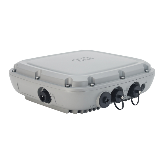
Introduction to Cisco Catalyst 9124AX Series Outdoor Access Point Cisco Catalyst 9124AX Series Outdoor Access Point is a Wi-Fi 6 technology based outdoor access point. This AP series has two models—one with omni antennas and the other with directional antennas, designed to use both the 2.4-GHz and the 5-GHz bands. - Page 10 • Integrated Bluetooth Low Energy (BLE) radio enables IoT use cases such as location tracking and wayfinding. • Cisco RF ASIC, a fully integrated Software Defined Radio (SDR), can perform advanced radio frequency (RF) spectrum analysis, and deliver features such as next–generation CleanAir, Wireless Intrusion Prevention System (WIPS), Dynamic Frequency Selection (DFS) detection.
-
Page 11: Ap Model Numbers And Regulatory Domains
You must verify whether the AP model you have is approved for use in your country. To verify approval and to identify the regulatory domain that corresponds to a particular country, visit http://www.cisco.com/go/aironet/compliance. Not all regulatory domains have been approved. As and when they are approved, the compliance list is updated. - Page 12 The C9124AXI-x and 9124AXD-x AP models have four internal dual-band antennas with dedicated 2.4-GHz and 5-GHz radios, one internal single-band antenna with a dedicated 2.4-GHz IoT radio, and one dual-band antenna with a dedicated 2.4-GHz and 5-GHz AUX radio. Cisco Catalyst 9124AX Series Outdoor Access Point Hardware Installation Guide...
-
Page 13: Hardware Features
Power Sources, on page 12 Access Point Views, Ports, and Connectors Cisco Catalyst 9124AX Series Outdoor AP has multiple options that you can use to power the AP or join the AP to the controller. Section Connectors and Ports, on page 5 show the connectors and ports for C9124AXI and C9124AXD models. - Page 14 So the wired0 MAC address is used for all data packets going out of the AP, including the dot1x packets. The only exception is the CDP and LLDP packets that would use the wired1 MAC address as the source-MAC. Cisco Catalyst 9124AX Series Outdoor Access Point Hardware Installation Guide...
-
Page 15: C9124Axi (Internal Antenna) Model: Antenna Radiation Patterns
Figure 2: Models C9124AXI and C9124AXD Left Side and Right Side Connectors and Ports Console Port Grounding Pad DC Power In C9124AXI (Internal Antenna) Model: Antenna Radiation Patterns The following illustrations show the C9124AXI model with internal antenna radiation patterns: Cisco Catalyst 9124AX Series Outdoor Access Point Hardware Installation Guide... - Page 16 Figure 4: C9124AXI Dual-Band Antenna Radiation Pattern (2.4 GHz Azimuth) Elevation) Figure 5: C9124AXI Dual-Band Antenna Radiation Pattern (5 GHz Figure 6: C9124AXI Dual-Band Antenna Radiation Pattern (5 GHz Azimuth) Elevation) Cisco Catalyst 9124AX Series Outdoor Access Point Hardware Installation Guide...
- Page 17 Figure 8: C9124AX IoT Antenna Radiation Pattern (2.4 GHz Elevation) Figure 9: C9124AXI AUX RF ASIC Antenna Radiation Pattern Figure 10: C9124AXI AUX RF ASIC Antenna Radiation Pattern (2.4 GHz Azimuth) (2.4 GHz Elevation) Cisco Catalyst 9124AX Series Outdoor Access Point Hardware Installation Guide...
-
Page 18: C9124Axd (Directional Antenna) Model: Antenna Radiation Patterns
The C9124AXD model with directional internal antenna has its radio radiation patterns shown in the following images: Figure 13: C9124AXD Dual-Band Antenna Radiation Pattern Figure 14: C9124AXD Dual-Band Antenna Radiation Pattern (2.4 GHz Azimuth) (2.4 GHz Elevation) Cisco Catalyst 9124AX Series Outdoor Access Point Hardware Installation Guide... - Page 19 Figure 16: C9124AXD Dual-Band Antenna Radiation Pattern (5 GHz Azimuth) Elevation) Figure 17: C9124AX IoT Antenna Radiation Pattern (2.4 GHz Figure 18: C9124AX IoT Antenna Radiation Pattern (2.4 GHz Azimuth) Elevation) Cisco Catalyst 9124AX Series Outdoor Access Point Hardware Installation Guide...
-
Page 20: Power Sources
Figure 22: C9124AXD AUX RF ASIC Antenna Radiation Pattern (5 GHz Azimuth) (5 GHz Elevation) Power Sources The Cisco Catalyst 9124AX Series Outdoor Access Point is supported on these power sources: • DC power: 24 to 56 VDC Cisco Catalyst 9124AX Series Outdoor Access Point Hardware Installation Guide... -
Page 21: Power Injectors
When the AP is installed outdoors or in a wet or damp location, the AC branch circuit powering the AP should be provided with ground fault protection (GFCI), as required by Article 210 of the National Electrical Code (NEC). Power Injectors The Cisco Catalyst 9124AX Series Outdoor Access Point supports the following power injectors: • AIR-PWRINJ-60RGD1= • AIR-PWRINJ-60RGD2= • AIR-PWRINJ6= •... - Page 22 The Ethernet cable must be a shielded, outdoor rated, Category 5e (CAT5e) or better cable. The AP senses the Ethernet and power signals and automatically switches internal circuitry to match the cable connections. Cisco Catalyst 9124AX Series Outdoor Access Point Hardware Installation Guide...
-
Page 23: Unpacking Your Access Point
Return the packing material to the shipping container and save it for future use. Step 3 Verify that you have received following items: • The access point • Accessory kit (Ethernet port termination plug, ground lug kit) Cisco Catalyst 9124AX Series Outdoor Access Point Hardware Installation Guide... -
Page 24: Optional Tools And Hardware From Cisco
Optional Tools and Hardware from Cisco • (Optional) Mounting brackets only if you opted for these when ordering the AP. If any item is missing or damaged, contact your Cisco representative or reseller for instructions. Optional Tools and Hardware from Cisco Depending on what you ordered, the following optional equipment may be part of your shipment: •... -
Page 25: Preinstallation Checks And Installation Guidelines
• If the SFP port is not in use, the port plug should remain in place and must be tightened to 12.5 lbf-in torque. If the DC, console, or PoE ports are not in use, the port cap should remain in place. Cisco Catalyst 9124AX Series Outdoor Access Point Hardware Installation Guide... -
Page 26: Typical Access Point Installation Components
Typical Access Point Installation Components The Cisco Catalyst 9124AX Series Outdoor Access Point is designed to be installed in an outdoor environment, such as the exterior roof overhang of a tall building or a streetlight pole. Carefully review the... - Page 27 Power cord better) cable Water drip loop Power injector 6-AWG copper grounding wire Shielded Ethernet (CAT5e or better) cable Ground rod Controller (through a switch) Independently sourced by the user. Cisco Catalyst 9124AX Series Outdoor Access Point Hardware Installation Guide...
- Page 28 Unpacking Your Access Point Typical Access Point Installation Components Cisco Catalyst 9124AX Series Outdoor Access Point Hardware Installation Guide...
-
Page 29: Installation Overview
For more information, see Mounting the Access Point, on page 24 section. • AP power options: 802.3at (PoE+), 802.3bt, Cisco Universal PoE (Cisco UPOE), and AC/DC External Power Supply (AIR-PWRADPT-RGD2=). Note When you use 802.3af to power an AP, both the 2.4-GHz and 5-GHz radios are disabled, and the Ethernet gets downgraded to 1–GbE speeds. -
Page 30: Performing A Preinstallation Configuration (Optional)
Procedure Step 1 Ensure that the Cisco Controller Distribution System port is connected to the network. Use the procedure for the CLI or the GUI interface, as described in the release appropriate Cisco Controller Configuration guide. Cisco Catalyst 9124AX Series Outdoor Access Point Hardware Installation Guide... - Page 31 Ensure that the AP has Layer 3 connectivity to the Cisco Controller Management and AP-Manager interfaces. b) Configure the switch to which the AP should be attached. See the release specific Cisco Wireless Controller Configuration Guide for the release your controller is running on.
-
Page 32: Mounting The Access Point
2 to 5 inch (51 to 127 mm). See: Vertically Mounting the AP with DC Supply to a Wall, on page 30 Vertically Mounting the AP with DC Supply to a Pole, on page 31 Cisco Catalyst 9124AX Series Outdoor Access Point Hardware Installation Guide... -
Page 33: Vertically Mounting The Ap To A Wall
You can use the mounting bracket as a template to mark the mounting holes' positions for your installation, install the mounting bracket, and then attach the AP to the bracket. Cisco Catalyst 9124AX Series Outdoor Access Point Hardware Installation Guide... - Page 34 Bracket mount holes for fastening bracket to the wall. You can use bolts of up to 1/4” or 6 mm in diameter. Figure 26: Mounting Bracket Dimensions Before you begin Ensure that you have the following materials before beginning to mount the AP to a wall: Cisco Catalyst 9124AX Series Outdoor Access Point Hardware Installation Guide...
- Page 35 Position the AP against the mounting bracket such that the four support bolts on the back of the AP slot into the keyhole slots on the mounting bracket. Step 5 Slide the AP down to sit securely in keyhole slots on the mounting bracket. Cisco Catalyst 9124AX Series Outdoor Access Point Hardware Installation Guide...
-
Page 36: Vertically Mounting The Ap To A Pole
Top and bottom sets of band clamp slots for passing the clamps through. Top and bottom steel band clamps Pole (wood, metal, or fiberglass), 2 to 5 inch (51 to 127mm) diameter Cisco Catalyst 9124AX Series Outdoor Access Point Hardware Installation Guide... - Page 37 Ensure that the clamps are tight enough not to let the AP move. Step 8 Proceed with installing antennas (only for external antenna models), connecting the data cables, grounding the AP, powering, and configuring the AP. Cisco Catalyst 9124AX Series Outdoor Access Point Hardware Installation Guide...
-
Page 38: Vertically Mounting The Ap With Dc Supply To A Wall
Table 4: Materials Required to Mount AP to a Wall using AIR-MNT-VERT2= Kit Materials Required Supplied in the Kit? Ground lug and screws (provided with the access point) Wall Mount Bracket Four M6 x 12-mm Hex-head Bolts Cisco Catalyst 9124AX Series Outdoor Access Point Hardware Installation Guide... -
Page 39: Vertically Mounting The Ap With Dc Supply To A Pole
The AIR-MNT-VERT2= fixed mounting kit contains a mounting bracket for both wall-mounting and pole-mounting, the AP, along with the power supply kit. This mounting kit supports metal, wood, or fiberglass poles from 2 to 5 inch (51 to 127 mm) in diameter. Cisco Catalyst 9124AX Series Outdoor Access Point Hardware Installation Guide... - Page 40 One wall mount bracket Four M6 x12 mm hex head bolts Four #8-32 screws to mount the power supply Three stainless steel band clamps (adjustable 2 to 5 inch (51 to 127 mm) Cisco Catalyst 9124AX Series Outdoor Access Point Hardware Installation Guide...
-
Page 41: Articulating Mount For The Ap To A Wall
The optional pivoting mounting kit AIR-MNT-ART1= contains a pivoting mounting bracket for both wall and pole mounting. This kit allows for adjusting the position of the AP by pivoting the AP along its vertical plane. Cisco Catalyst 9124AX Series Outdoor Access Point Hardware Installation Guide... - Page 42 This is the AP-plate end of the bracket and is steel band clamps in pole-mount installations. fastened to the back of the AP. Wall-plate end of the bracket. This plate is fastened to the wall. Cisco Catalyst 9124AX Series Outdoor Access Point Hardware Installation Guide...
- Page 43 Pole-mount screw clamp M8 spring washer Pivoting bracket base plate M8 nut Before you begin Ensure that you have the following materials before beginning to mount the AP to a wall: Cisco Catalyst 9124AX Series Outdoor Access Point Hardware Installation Guide...
- Page 44 Fasten the bracket plate to the AP by using four M6 x12 mm bolts and a 10–mm box or socket wrench. Tighten the bolts to 40 lbf-in (4.5 Nm) of torque. Cisco Catalyst 9124AX Series Outdoor Access Point Hardware Installation Guide...
-
Page 45: Articulating Mount For The Ap To A Pole
Figure 33: AP Pole Mounted Using the Pivoting Mounting Bracket One of four mounting holes for mounting the Steel band clamps AP to the bracket Slots for band clamps Pole Cisco Catalyst 9124AX Series Outdoor Access Point Hardware Installation Guide... - Page 46 Two stainless steel band clamps (adjustable 2 to 5 inch (51 to 127mm) Crimping tool for ground lug, Panduit CT0720 with CD-720-1 die Four wall mounting screws (6 mm max) Cisco Catalyst 9124AX Series Outdoor Access Point Hardware Installation Guide...
-
Page 47: Wall Mounting The Ap With Horizontal Kit
Caution The mounting wall, attaching screws, and wall anchors must support the least 50-lb (22.7–kg) static weight. The installer must supply proper screws and anchors in accordance with local codes. Cisco Catalyst 9124AX Series Outdoor Access Point Hardware Installation Guide... - Page 48 See Figure 36: L-bracket AP mount dimensions, on page 41 for dimensions of the mounting L-bracket. Figure 35: Wall mount L-bracket screw hole dimensions Cisco Catalyst 9124AX Series Outdoor Access Point Hardware Installation Guide...
-
Page 49: Pole Mounting The Ap With Horizontal Kit
Using this kit, you can install the AP on a pole or mast. It supports metal, wood, or fiberglass poles from 2 to 5 inches (51 to 127 mm) in diameter. Cisco Catalyst 9124AX Series Outdoor Access Point Hardware Installation Guide... - Page 50 Wall/Pole Mount L-Bracket Solar Shield (4) M6 x 12-mm Hex-head Bolts (2) Adjustable Band Clamps 2 to 5 inch (51 to 127 mm) Dia (4) 8-32 x 0.62” Phillips Pan Head Screw Cisco Catalyst 9124AX Series Outdoor Access Point Hardware Installation Guide...
-
Page 51: Dc Supply Mount Bracket
(For example: indoors or under an eave), the solar shield is not required. DC Supply Mount Bracket The AIR-ACC-PS-MNT1= bracket is an orderable option to mount a DC supply to the AIR-MNT-HORZ1= L-bracket kit. Cisco Catalyst 9124AX Series Outdoor Access Point Hardware Installation Guide... - Page 52 DC Supply Mount Bracket Figure 38: Installing the DC supply bracket on to the L-bracket DC supply mount bracket 8-32 x 0.62 lg Bracket screws DC Supply Figure 39: DC Supply Bracket Dimensions Cisco Catalyst 9124AX Series Outdoor Access Point Hardware Installation Guide...
-
Page 53: Strand Mounting The Ap
The SMK can also accommodate up to 10 degrees of strand or cable droop. Figure 40: SMK Bracket Assembly Dimensions with Mounted AP Figure 41: Assembling the cable bracket and Clamps SMK Upper Bracket 5/16-18 Hex Nut with Serrated flange Cisco Catalyst 9124AX Series Outdoor Access Point Hardware Installation Guide... - Page 54 Supplied in the Kit? Strand Mount Kit (including hardware) Solar Shield Cover (2) M8 x 16 mm Button head hex bolts (2) M8 split lock washer (2) M8 flat lock washer Cisco Catalyst 9124AX Series Outdoor Access Point Hardware Installation Guide...
- Page 55 15 lbf-in (17 kgf-cm) of torque. Step 6 Connect the data cables, ground the AP, and power the AP. Cisco Catalyst 9124AX Series Outdoor Access Point Hardware Installation Guide...
-
Page 56: Ap Paintable Cover Kit
AP. Figure 44: AP with Paintable Cover Kit Figure 45: Installing the AP Cover on an Installed AP Cisco Catalyst 9124AX Series Outdoor Access Point Hardware Installation Guide... -
Page 57: Grounding The Access Point
If necessary, strip the other end of the ground wire and connect it to a reliable earth ground, such as a grounding rod or an appropriate grounding point on a metal streetlight pole that is grounded. Cisco Catalyst 9124AX Series Outdoor Access Point Hardware Installation Guide... -
Page 58: Powering The Access Point
These power injectors support 10/100/1000BASE-T operation only. They do not support the 2.5GBAST-T (mGig) Ethernet speed. Table 11: Cisco Catalyst 9124AX AP Reduced Power Feature Matrix PoE-in/DC Radio 0 Radio Ethernetm PoE-out Notes Input Radio Module Path Path Cisco Catalyst 9124AX Series Outdoor Access Point Hardware Installation Guide... -
Page 59: Connecting A Power Injector
Connect a CAT5e or better Ethernet cable from your wired LAN network to the power injector. Danger To reduce the risk of fire, use only No. 24 AWG or larger telecommunication line cord. Statement 1023 Cisco Catalyst 9124AX Series Outdoor Access Point Hardware Installation Guide... -
Page 60: Connecting A Dc Power Cable To The Access Point
IEC 60950 based safety standards. Statement 1033 To connect a DC power cable, you need to supply these tools and material: • Cisco orderable option DC power supply (AIR-PWRADPT-RGD2=) with an attached 2-pin connector or Two-pin DC power connector (supplied with Cisco AIR-ACC-KIT1= kit) •... - Page 61 2-Pin DC plug Step 5 If the AP is to be power with customer supplied DC source. The following steps show how to terminate the Cisco-supplied DC plug to the cable. Cisco Catalyst 9124AX Series Outdoor Access Point Hardware Installation Guide...
- Page 62 Slide the gasket and seal the ring down the cable, thread the ring on to the body. Use caution to be sure the gasket is correctly seated into the ring. Hand tighten to seal gasket fully. Cisco Catalyst 9124AX Series Outdoor Access Point Hardware Installation Guide...
-
Page 63: Connecting Data Cables
Verify that the cable gland has a rubber seal and ensure that it is not damaged. Caution If the cable gland and rubber gasket is not installed correctly, it causes the cable grip to leak. Cisco Catalyst 9124AX Series Outdoor Access Point Hardware Installation Guide... -
Page 64: Connecting A Fiber-Optic Cable To The Ap (Air-Spf-Kit1=)
Turn on the power to the power injector. Connecting a Fiber-optic Cable to the AP (AIR-SPF-KIT1=) The optional Cisco accessory fiber-optic kit enables the AP to support fiber-optic network connections. You can connect the fiber-optic networking cable to the SFP port. The small form-factor pluggable (SFP) transceiver module connects the cable to the SFP port. - Page 65 • Adjustable wrench Procedure Step 1 Disconnect all power sources from the AP. Step 2 Remove the plug from the SFP port by following the guidelines given in this step. Cisco Catalyst 9124AX Series Outdoor Access Point Hardware Installation Guide...
- Page 66 Figure 55: Exploded view of Fiber-Optic cable and Gland assembly SFP Transceiver Module Gland Compression Ferrule Duplex LC Fiber-optic cable Large Cable Rubber Gland 0.30 to 0.50 inch (7.6 to 12.7 mm) diameter Cisco Catalyst 9124AX Series Outdoor Access Point Hardware Installation Guide...
- Page 67 To seal the rubber gland to the fiber cable, hand tighten the gland nut. Using an adjustable wrench, tighten the nut ¼ revolution to make a water-tight seal on the cable to approximately 15 to 22 lbf-in (17 to 25 kgf-cm) torque. Cisco Catalyst 9124AX Series Outdoor Access Point Hardware Installation Guide...
-
Page 68: Powering The Access Point Over Power-Over-Ethernet
Powering the Access Point over Power-over-Ethernet The AP can be powered through Power-over-Ethernet (PoE) using the following: • 802.3at (PoE+): Any 802.3at (30W) compliant switch port or Cisco Power Injector AIR-PWRINJ6= • 802.3bt: Any 802.3bt compliant switch port or IEEE 802.3bt compliant Power Injector •... -
Page 69: Configuring And Deploying The Access Point
Checking the Access Point LEDs, on page 62 Controller Discovery Process The Cisco AP must join a controller to function as an AP and start serving clients. Cisco uses a process called controller discovery process to join a controller. The devices use Lightweight Access Point Protocol (LWAPP) to communicate with each other. -
Page 70: Deploying The Access Point In A Wireless Network
When an AP receives an IP address and DNS information from a DHCP server, it contacts the DNS to resolve CISCO-CAPWAP-CONTROLLER.localdomain. When the DNS sends a list of controller IP addresses, the AP sends discovery requests to the controllers. - Page 71 There is an Ethernet failure or an image recovery (the Reset button has been pushed for 20-30 seconds) Blinking Green Image recovery is in progress (the Reset button has been released) Cisco Catalyst 9124AX Series Outdoor Access Point Hardware Installation Guide...
- Page 72 Configuring and Deploying the Access Point Checking the Access Point LEDs Cisco Catalyst 9124AX Series Outdoor Access Point Hardware Installation Guide...
-
Page 73: Troubleshooting
C H A P T E R Troubleshooting • Troubleshooting the Access Point to Cisco Controller Join Process, on page 65 • Important Information for Controller-based Deployments, on page 66 • Configuring DHCP Option 43, on page 66 Troubleshooting the Access Point to Cisco Controller Join Process AP can fail to join a controller for many reasons: a RADIUS authorization is pending;... -
Page 74: Important Information For Controller-Based Deployments
DHCP Option 43 is limited to one AP type per DHCP pool. You must configure a separate DHCP pool for each AP type. The Cisco Catalyst 9124AX Series Outdoor AP uses the type-length-value (TLV) format for DHCP Option 43. DHCP servers must be programmed to return the option based on the AP DHCP Vendor Class Identifier (VCI) string (DHCP Option 43). - Page 75 10.127.127.2. The type is f1(hex). The length is 2 * 4 = 8 = 08 (hex). The IP addresses translate to 0a7e7e02 and 0a7f7f02. Assembling the string then yields f1080a7e7e020a7f7f02. The resulting Cisco IOS command added to the DHCP scope is option 43 hex f1080a7e7e020a7f7f02.
- Page 76 Troubleshooting Configuring DHCP Option 43 Cisco Catalyst 9124AX Series Outdoor Access Point Hardware Installation Guide...
-
Page 77: Safety Guidelines And Warnings
Safety Guidelines and Warnings Translated versions of the following safety warnings are provided in the translated safety warnings document shipped with your AP. The translated warnings are also in the Translated Safety Warnings for Cisco Catalyst Access Points, available on Cisco.com. - Page 78 Ultimate disposal of this product should be handled according to all national laws and regulations. Statement 1040 Danger When installing or replacing the unit, the ground connection must always be made first and disconnected last. Statement 1046. Danger Class 1 Laser Product. Statement 1008 Cisco Catalyst 9124AX Series Outdoor Access Point Hardware Installation Guide...
- Page 79 Electrical Code, Part 1, CSA C22.2. External power supply, power adapter and/or power injector, if provided, are not suitable for installation in air spaces. Statement 440 • FCC Safety Compliance Statement, on page 72 • Safety Precautions, on page 72 Cisco Catalyst 9124AX Series Outdoor Access Point Hardware Installation Guide...
-
Page 80: Fcc Safety Compliance Statement
The FCC, with its action in ET Docket 96-8, has adopted a safety standard for human exposure to RF electromagnetic energy emitted by FCC-certified equipment. When used with approved Cisco antennas, Cisco Catalyst products meet the uncontrolled environmental limits found in OET-65 and ANSI C95.1, 1991. Proper operation of this radio device according to the instructions in this publication results in user exposure substantially below the FCC recommended limits. -
Page 81: Performing Site Surveys
• Data rates: Sensitivity and range are inversely proportional to data bit rates. The maximum radio range is achieved at the lowest workable data rate. A decrease in receiver sensitivity occurs as the radio data increases. Cisco Catalyst 9124AX Series Outdoor Access Point Hardware Installation Guide... - Page 82 • Have you configured the APs before you go onsite? It is always easier to resolve configurations or device problems first. • Do you have the proper tools and equipment to complete your survey? Cisco Catalyst 9124AX Series Outdoor Access Point Hardware Installation Guide...
-
Page 83: Declarations Of Conformity And Regulatory Information
C H A P T E R Declarations of Conformity and Regulatory Information This section provides declarations of conformity and regulatory information for the Cisco Catalyst 9124AX Series Outdoor APs. You can find additional information at this URL: www.cisco.com/go/aironet/compliance •... -
Page 84: Operation Of Cisco Catalyst Access Points In México
Interference from Information Technology Equipment (VCCI). If this is used near a radio or television receiver in a domestic environment, it may cause radio interference. Install and use the equipment according to the instruction manual. Cisco Catalyst 9124AX Series Outdoor Access Point Hardware Installation Guide... -
Page 85: Guidelines For Operating Cisco Catalyst Access Points In Japan
Guidelines for Operating Cisco Catalyst Access Points in Japan Danger Guidelines for Operating Cisco Catalyst Access Points in Japan This section provides guidelines for avoiding interference when operating Cisco Catalyst access points in Japan. These guidelines are provided in both Japanese and English. English Translation... -
Page 86: Statement 371-Power Cable And Ac Adapter
Safety Law prohibits the use of UL-certified cables (that have the “UL” shown on the code) for any other electrical devices than products designated by CISCO. The use of cables that are certified by Electrical Appliance and Material Safety Law (that have “PSE” shown on the code) is not limited to CISCO-designated products. - Page 87 List of Internal Antennas Supported on C9124AXD Antenna Type Antenna Gain Antenna Impedance Single-Port Single-Band omni (Mixed POL) 4 dBi 50 ohms BLE/IOT Single-Port Dual-Band Omni (VPOL) AUX 2.4 GHz—9 50 ohms 5 GHz—9 dBi Cisco Catalyst 9124AX Series Outdoor Access Point Hardware Installation Guide...
-
Page 88: Industry Canada
This equipment is intended to be used in all EU and EFTA countries. Outdoor use may be restricted to certain frequencies and/or may require a license for operation. For more details, contact Cisco Corporate Compliance. The product carries the CE Mark:... -
Page 89: Administrative Rules For Cisco Catalyst Access Points In Taiwan
Administrative Rules for Cisco Catalyst Access Points in Taiwan Administrative Rules for Cisco Catalyst Access Points in Taiwan This section provides administrative rules for operating Cisco Catalyst APs in Taiwan. The rules for all access points are provided in both Chinese and English. -
Page 90: Operation Of Cisco Catalyst Access Points In Brazil
Operation of Cisco Catalyst Access Points in Brazil This section contains special information for operation of Cisco Catalyst APs in Brazil. Access Point Models Certification Number... -
Page 91: Declaration Of Conformity For Rf Exposure
This Device Meets International Guidelines for Exposure to Radio Waves The Cisco Catalyst 9124AX Series Outdoor AP device includes a radio transmitter and receiver. It is designed not to exceed the limits for exposure to radio waves (radio frequency electromagnetic fields) recommended by international guidelines. -
Page 92: This Device Meets Fcc Guidelines For Exposure To Radio Waves
This Device Meets FCC Guidelines for Exposure to Radio Waves The Cisco Catalyst 9124AX Series Outdoor AP device includes a radio transmitter and receiver. It is designed not to exceed the limits for exposure to radio waves (radio frequency electromagnetic fields) as referenced in FCC Part 1.1310. -
Page 93: This Device Meets The Industry Canada Guidelines For Exposure To Radio Waves
This Device Meets the Industry Canada Guidelines for Exposure to Radio Waves The Cisco Catalyst 9124AX Series Outdoor AP device includes a radio transmitter and receiver. It is designed not to exceed the limits for exposure to radio waves (radio frequency electromagnetic fields) as referenced in Health Canada Safety Code 6. -
Page 94: Additional Information On Rf Exposure
Additional Information on RF Exposure You can find additional information on the subject at the following links: • Cisco Systems Spread Spectrum Radios and RF Safety white paper at this URL: http://www.cisco.com/warp/public/cc/pd/witc/ao340ap/prodlit/rfhr_wi.htm • FCC Bulletin 56: Questions and Answers about Biological Effects and Potential Hazards of Radio Frequency Electromagnetic Fields •...