
Related Manuals for Agilent Technologies 16900A


Summary of Contents for Agilent Technologies 16900A
- Page 1 Agilent 16900A, 16902A, and 16903A Logic Analysis System Service Guide Agilent Technologies...
- Page 2 Notices © Agilent Technologies, Inc. 2004 Manual Part Number computer software” as defined in FAR 52.227-19 (June 1987) or any equivalent No part of this manual may be reproduced 16900-97010 agency regulation or contract clause. Use, in any form or by any means (including...
-
Page 3: The Agilent 16900-Series Logic Analysis Systems - At A Glance
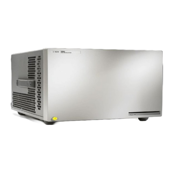
The Agilent 16900-series Logic Analysis Systems - At a Glance The Agilent Technologies 16900- series logic analysis systems are modular systems with slots for logic analyzer and other types of measurement modules. 16902A or 16903A 16900A Logic Analysis Logic Analysis... -
Page 4: Supplied Accessories
This service guide contains information for finding a defective assembly by testing and servicing the 16900A/16902A/16903A. This instrument can be returned to Agilent Technologies for all service work, including troubleshooting. Contact your nearest Agilent Technologies Sales Office for more details. -
Page 5: In This Service Guide
In this Service Guide This book is the service guide for the 16900A/16902A/16903A Logic Analysis System and is divided into eight chapters. Chapter 1, “General Information” contains information about the instrument including accessories, specifications and characteristics, and a list of the equipment required for servicing the instrument. - Page 6 16900A, 16902A, and 16903A Service Guide...
-
Page 7: Table Of Contents
To connect multiple frames To install measurement modules To clean the instrument Testing Performance Testing Performance Self-Tests Test Interval To perform the power-up tests Calibrating and Adjusting Calibration Strategy Calibrations and Adjustments for Modules 16900A, 16902A, and 16903A Service Guide... - Page 8 Troubleshooting To use the16900A and 16902A flowcharts Figure 1. 16900A and 16902A Troubleshooting Flowchart Figure 2. 16900A and 16902A Power Troubleshooting Flowchart Figure 3. 16900A and 16902A Display Troubleshooting Flowchart Figure 4. 16900 and 16902A Boot UpTroubleshooting Flowchart Figure 5. 16900A and 16902A Application Troubleshooting...
- Page 9 16900A and 16902A power supplies 16903A power supply To remove and replace the card cage and fans 16900A and 16902A card cage and fans To remove and replace the line filter assembly To remove and replace the module interface board...
- Page 10 16900A and 16902A Frames Table 4. Replaceable parts for the 16900A and 16902A frames 16903A Frame Table 5. Replaceable parts for the 16903A frame Power Cables and Plug Configurations Table 6. Power Cables and Plug Configurations Theory of Operation Theory of Operation...
-
Page 11: General Information
Agilent 16900A, 16902A, and 16903A Logic Analysis System Service Guide General Information Electrical and Operating Environment Characteristics Dimensions Agilent Technologies... -
Page 12: Electrical And Operating Environment Characteristics
For indoor use only. Temperature Instrument (16900A & 16902A): 0° to + 40° C (+32° to +104° F) Instrument (16903A): 0° to + 50° C (+32° to +122° F) Disk Media: 10° to + 40° C (+50° to +104° F) Probes/cables: 0°... -
Page 13: Dimensions
Clock In The Clock In connector is 5.5V Max pk and DC, CAT I (line isolated). Dimensions The following figure provides dimensions for the 16900 series logic analyzer mainframes in centimeters and inches. 16900A, 16902A, and 16903A Service Guide... - Page 14 General Information 16900A, 16902A, and 16903A Service Guide...
- Page 15 Agilent 16900A, 16902A, and 16903A Logic Analysis System Service Guide Preparing for Use To inspect the logic analysis system To apply power To connect multiple frames To install measurement modules To clean the instrument Agilent Technologies...
-
Page 16: Preparing For Use
The 16900A and 16902A should only be used with the notched power cord provided due to the high power requirements of the instruments. Refer to “Power... -
Page 17: To Connect Multiple Frames
16900A and 16902A frames together. Refer to the Installation Guide that came with your instrument for Multiframe Pro configurations. To get the most up- to- date installation guide: •... - Page 18 Preparing for Use 16900A, 16902A, and 16903A Service Guide...
-
Page 19: Testing Performance
Agilent 16900A, 16902A, and 16903A Logic Analysis System Service Guide Testing Performance Testing Performance To perform the power-up tests Agilent Technologies... -
Page 20: Testing Performance
There is no recommended test interval for the 16900- series mainframes. However, each of the supported modules has performance verification tests and therefore require a periodic verification of specifications. Refer to the Service Guides of the individual modules for more information. 16900A, 16902A, and 16903A Service Guide... -
Page 21: To Perform The Power-Up Tests
Self- Tests. Tests that are performed during powerup are not repeated in the Self- Tests. A monitor (16900A only), keyboard and mouse must be connected to the mainframe to observe the results of the power- up tests. - Page 22 Testing Performance 16900A, 16902A, and 16903A Service Guide...
-
Page 23: Calibrating And Adjusting
Agilent 16900A, 16902A, and 16903A Logic Analysis System Service Guide Calibrating and Adjusting Calibration Strategy Calibrations and Adjustments for Modules Agilent Technologies... -
Page 24: Calibration Strategy
Calibrations and Adjustments for Modules The individual modules that plug into the 16900- series mainframes may require calibration, operational accuracy calibration, or adjustments. Refer to the “Testing Performance” chapter in the service manual for the module. 16900A, 16902A, and 16903A Service Guide... - Page 25 Agilent 16900A, 16902A, and 16903A Logic Analysis System Service Guide Troubleshooting Troubleshooting To use the16900A and 16902A flowcharts To use the16903A flowcharts To troubeshoot power problems To check the power supply voltages To run the self-tests Troubleshooting the CD-ROM drive...
-
Page 26: Troubleshooting
The service strategy for this instrument is the replacement of defective assemblies. This instrument can be returned to Agilent Technologies for all service work, including troubleshooting. Contact your nearest Agilent Technologies Sales Office for more details. - Page 27 Troubleshooting Figure 1 16900A and 16902A Troubleshooting Flowchart Start Attach keyboard, mouse and power cord. Attach the external display for 16900A. Remove all user-installed PCI cards (see'To remove & replace optional interface cards' in chapter 7). Apply power. Are the fans turning &...
- Page 28 Troubleshooting Figure 2 16900A and 16902A Power Troubleshooting Flowchart Remove power plug for 15 seconds to reset power supplies. Apply power. Are the fans turning & power on? Are the Is the MIB green/yellow module interface The power down signal is...
- Page 29 Troubleshooting Figure 3 16900A and 16902A Display Troubleshooting Flowchart Check all cables to the front panel Is there assembly. Check all cables to the any boot dialog at CPU motherboard. Ensure the PCI any time? bridge board is fully seated. Reseat as necessary.
- Page 30 Run the #7 in the boot steady recovery disk. sequence? Blank screen/display problem due to the display mode. Reboot. At Select OS menu, press F8 to open advanced startup. Select "enable VGA mode" then Continue. 16900A, 16902A, and 16903A Service Guide...
- Page 31 Troubleshooting Figure 5 16900A and 16902A Application Troubleshooting Flowchart Try each of the following steps in order. Return to between each. Reinstall the logic analyzer application. Check all cables to front panel assembly . Check all cables to CPU motherboard.
-
Page 32: To Use The16903A Flowcharts
A circled alpha references connections within the flowchart. Start your troubleshooting at the top of the first flowchart (Figure 6 on page 33). 16900A, 16902A, and 16903A Service Guide... - Page 33 Does the logic analyzer application start? Run the module self tests. Go to module the self tests troubleshooting. pass? Is the problem still Call Agilent support. present? Done. 16900A, 16902A, and 16903A Service Guide...
- Page 34 Are power supply defective voltages correct? power supply. Replace the CPU. Check for a power short, burnt components, traces, etc. Replace the MIB. Is there Replace the a power damaged short? component. Replace the MIB. 16900A, 16902A, and 16903A Service Guide...
- Page 35 (16-bit color depth). monitor? Is the Replace the CPU built-in display motherboard. completely dark? , and then & return to Return to between each. Replace the LCD panel. Replace the MIB. Replace the PCI bridge board. 16900A, 16902A, and 16903A Service Guide...
- Page 36 Run the in the boot steady recovery disk. sequence? Blank screen/display problem due to display mode. Reboot. At Select OS menu, press F8 to open advanced startup. Select "enable VGA mode" then Continue. 16900A, 16902A, and 16903A Service Guide...
- Page 37 Reinstall the logic analyzer application. Check all cables to front panel assembly . Check all cables to CPU motherboard. Check all cables to IO board. Reseat as necessary. Replace the MIB board. Replace the PCI bridge board. 16900A, 16902A, and 16903A Service Guide...
-
Page 38: To Troubeshoot Power Problems
If it just powers down, it is a power supply problem On the 16900A and 16902A frames, if the lights do not come on and if the system powers up momentarily when you plug it in, make sure the power buttons haven't become jammed or stuck in the pushed in position. - Page 39 Using a voltmeter, ensure the AUX +5V power on the MIB measures +5V. If it does not, replace the power supply. Apply power and return to “16900A and 16902A Power Troubleshooting Flowchart" on page 28. 16900A, 16902A, and 16903A Service Guide...
-
Page 40: To Check The Power Supply Voltages
16900A and 16902A power supplies The 16900A and 16902A systems have two power supplies. One is 700 watts and the other is 500 watts. Use the following graphics when measuring the voltages. -
Page 41: 16903A Power Supply
The 700 watt power supply in the 16903A system is different than the one in the 16900/02A systems. Use the following graphics when measuring the voltages on the 16903A power supply. 700 watt power supply voltages 16900A, 16902A, and 16903A Service Guide... -
Page 42: To Run The Self-Tests
Troubleshooting To run the self-tests In the Agilent logic analyzer application, click Help>Self Test. In the Analysis System Self Test dialog, double click on the test you want to run. 16900A, 16902A, and 16903A Service Guide... -
Page 43: Troubleshooting The Cd-Rom Drive
• Can read DVD- RAM, DVD- R and DVD- RW. • Buffer Under Run Protection. • Writing Method: • Disc at Once. • Session at Once. • Track at Once. • Multi- Session. • Fixed/Variable Packet Writing. 16900A, 16902A, and 16903A Service Guide... -
Page 44: To Reinstall The Operating System
Running the recovery disks will reformat your hard drive. All data C A U T I O N files and programs will be overwritten. Save your data to CD or to another machine before performing this procedure. 16900A, 16902A, and 16903A Service Guide... -
Page 45: Replacing Assemblies
Agilent 16900A, 16902A, and 16903A Logic Analysis System Service Guide Replacing Assemblies 16900-Series Disassembly/Assembly To prepare the instrument for disassembly To remove and replace optional modules or filler panels To remove and replace the cover To remove and replace the CPU tray... -
Page 46: 16900-Series Disassembly/Assembly
Tools Required • T6, T10, T15, T20 TORX screwdrivers • #1 Pozidrive screwdriver • 1/8- inch screwdriver • 13/16- inch, deep- well nut driver • 1/4- inch hex socket • 3/16- inch nut driver 16900A, 16902A, and 16903A Service Guide... -
Page 47: To Save The License File
File>Write these files to CD To obtain the licensing host ID In the Logic Analyzer application, go to Help>Software Licensing. Choose the tab ‘How to install a license’. The Licensing Host ID will be displayed on this page. 16900A, 16902A, and 16903A Service Guide... -
Page 48: To Prepare The Instrument For Disassembly
Down or if you are running remote desktop, click Start> Settings> Windows Security> Shut Down. This software power off does the following: • Closes all programs that are running. • Writes all data to the disk. • Turns off the power supply. 16900A, 16902A, and 16903A Service Guide... - Page 49 Unplugging power while the instrument is turned on or a power loss is similar to the long press of the power button with one exception: • When the system is plugged back in, it will power up and boot into Windows. 16900A, 16902A, and 16903A Service Guide...
-
Page 50: To Remove And Replace Optional Modules Or Filler Panels
Open position Locked position The following figure shows a 6- card frame. The insertion/removal order would be the same for a 3- card frame. A single- module configuration can be installed in any available slot. 16900A, 16902A, and 16903A Service Guide... - Page 51 (2 in- lb maximum). For correct air circulation, install filler panels in all unused card slots. Correct air circulation keeps the instrument from overheating. Keep any extra filler panels for future use. 16900A, 16902A, and 16903A Service Guide...
-
Page 52: To Remove And Replace The Cover
Reverse this procedure to replace the cover. When reinstalling the handle assembly, ensure that the screws are C A U T I O N torqued to 2.372 Newton meters (21 inch pounds) so that they do not work themselves loose. 16900A, 16902A, and 16903A Service Guide... -
Page 53: To Remove And Replace The Cpu Tray
“To remove and replace the cover" on page 52 Disconnect cables from the module interface board. Module Interface Board CD ROM cable CPU power Remove 7 screws from the back of the CPU tray using a Torx T10 screwdriver. 16900A, 16902A, and 16903A Service Guide... -
Page 54: 16903A Cpu Tray
Reverse this procedure to install the CPU tray. 16903A CPU tray Perform previous procedures: • “To prepare the instrument for disassembly" page 48 • “To remove and replace the cover" on page 52 Disconnect cables from the module interface board. 16900A, 16902A, and 16903A Service Guide... - Page 55 Remove 9 screws from the back of the CPU tray using a Torx T10 screwdriver. T10 screws (9) Slide the tray out being careful not to catch the loose cables on anything. Reverse this procedure to install the CPU tray. 16900A, 16902A, and 16903A Service Guide...
-
Page 56: To Remove And Replace The Pci Board
CPU Tray Reverse this procedure to install the PCI board. 16903A PCI board Perform previous procedures: • “To prepare the instrument for disassembly" page 48 • “To remove and replace the cover" on page 52 16900A, 16902A, and 16903A Service Guide... - Page 57 Pull the board up to disconnect it from the PCI socket on the motherboard. T-10 Screw PCI Cable PCI Board Retainer Touch Screen Cable PCI Socket on 16903A PCI Board Motherboard CPU Tray T-10 Screws (2) Reverse this procedure to install the PCI board. 16900A, 16902A, and 16903A Service Guide...
-
Page 58: To Remove And Replace Optional Interface Cards
CPU tray between the motherboard and the rear panel. Press the card securely into the socket on the motherboard. For cards in the tall slot(s), swing the plate back into place. Replace the screw(s). 16900A, 16902A, and 16903A Service Guide... - Page 59 Replacing Assemblies T10 Screw Interface Cards Tab on Card Card Socket Plate on Rear Panel Motherboard Tall Slot Bottom of CPU Tray Rear Panel 16900A, 16902A, and 16903A Service Guide...
-
Page 60: To Remove And Replace The I/O Board
I/O board to the CPU tray. T-10 Screw (1) I/O Board Multiframe Connectors 16900/02A Rear Panel Front Panel Reset Cable Pozidrive Screws (4) Hex Nuts (4) Reverse this procedure to install the I/O board. 16900A, 16902A, and 16903A Service Guide... -
Page 61: 16903A I/O Board
Using a Torx T10 screwdriver, remove the 2 screws securing the I/O board to the rear panel. Slide the I/O panel out. I/O Cable T10 Screw I/O Board Assembly T10 Screw 4 Reverse this procedure to install the I/O board. 16900A, 16902A, and 16903A Service Guide... -
Page 62: To Remove And Replace The Hard Disk Drive
Reverse this procedure to install the hard disk drive. Follow the instructions on the recovery CD to restore your system software. Hard CPU Tray Drive Hard Drive Power Cable Hard Drive Cable T-10 Screws (4) 16900A, 16902A, and 16903A Service Guide... -
Page 63: To Remove And Replace The Motherboard
CPU tray. Screws CD-ROM Screws (3) Cable Connector Power Cable Reset Connector Cable Bracket Reset Cable Motherboard (Representative drawing. Screws (2) Yours may look different) Studs (6) Reverse this procedure to install the CPU tray. 16900A, 16902A, and 16903A Service Guide... -
Page 64: To Remove And Replace The Front Panel Assembly
Screws (4) Chassis Module Module Power Screws (4) Interface Interface On|Off Front Board Board Cable Panel Power On|Off Cable Cable CD-ROM CD-ROM Cable Cable Alignment Alignment Reverse this procedure to install the front panel assembly. 16900A, 16902A, and 16903A Service Guide... -
Page 65: To Remove And Replace The Cd-Rom Drive
CD- ROM board to the drive and remove the board. CD-ROM board T6 Screws (2) Bracket T6 Screws (2) Front Panel T10 Screws (2) CD-ROM Bracket CD-ROM Drive Reverse this procedure to reassemble and install the drive. 16900A, 16902A, and 16903A Service Guide... -
Page 66: To Remove And Replace The Touch-Screen Controller Board
Using a Torx T6 screwdriver, remove the 2 screws securing the board to the front panel board. Touch-Screen Controller Board T6 Screw T6 Screw Touch-Screen Cable Assembly Jumper 8-Wire Touch-Screen Cable 16900A, 16902A, and 16903A Service Guide... - Page 67 Replacing Assemblies Ensure the jumper on J1 connector has the top/inside pin exposed when replacing. 16900A, 16902A, and 16903A Service Guide...
-
Page 68: To Remove And Replace The Backlight Inverter Board
Using a Torx T6 screwdriver, remove the 2 screws securing the board to the front panel board. Backlight Inverter Board Inverter Cable T6 Screws (2) LCD Cable (pink) Reverse this procedure to install the backlight inverter board. 16900A, 16902A, and 16903A Service Guide... -
Page 69: To Remove And Replace The Front Panel Interface Board
Using a Torx T10 screwdriver, remove the screw that secures the front panel interface board to the LCD bracket assembly. Push board slightly down to remove standoffs from the 4 keyholes then remove the board. 16900A, 16902A, and 16903A Service Guide... - Page 70 Replacing Assemblies Front Panel Interface Board T10 Screw LCD Cable Keyholes (4) Keyboard Cable 16900A, 16902A, and 16903A Service Guide...
-
Page 71: To Remove And Replace The Lcd Bracket Assembly
Using a Torx T10 screwdriver, remove the 6 screws that secure the LCD bracket assembly to the front frame. Feed the cables through the bracket and remove. Use the guide pins to align the bracket when re- assembling. Guide Pins Screws (6) 16900A, 16902A, and 16903A Service Guide... -
Page 72: To Remove And Replace The Touch-Screen/Display Assembly
Gently pry the touch screen from the LCD display. It is held on with double- sided tape. Using a Torx T10 screwdriver, remove the 4 screws securing the LCD display to the LCD bracket. 16900A, 16902A, and 16903A Service Guide... - Page 73 Press on the LCD bracket assembly firmly to ensure the LCD display is attached to the touch screen. Using a Torx T10 screwdriver, screw the 6 screws into the LCD bracket to secure it to the front frame. 16900A, 16902A, and 16903A Service Guide...
-
Page 74: To Remove And Replace The Keypad And Keypad Board
Finger oils can impair contact. If necessary, carefully clean the contacts using alcohol and lint-free swabs or wipes. Reverse this procedure to install the keypad and keypad board. 16900A, 16902A, and 16903A Service Guide... - Page 75 Replacing Assemblies Front Frame T10 Screw (1) Keypad Board Cursor Knob Keypad 18 mm Knobs (2) 12 mm Knobs (3) Front Panel Label 16900A, 16902A, and 16903A Service Guide...
-
Page 76: To Remove And Replace The On|Off Key
Finger oils can impair contact. If necessary, carefully clean the contacts using alcohol and lint-free swabs or wipes. T6 Screw (1) On|Off Board Front Shoulder Frame Screw On|Off Cable On|Off Keypad 16900A, 16902A, and 16903A Service Guide... -
Page 77: To Remove And Replace The Power Supplies
“To remove and replace the cover" on page 52 • “To remove and replace the front panel assembly" page 64 Disconnect the following cables on both power supplies: • Power Cable • Sense Cable • 12- Position Cable 16900A, 16902A, and 16903A Service Guide... -
Page 78: 16903A Power Supply
Power Cable • Sense Cable • 24- Position Cable • 22- Position Cable • 16- Position Cable Using Torx T20 and T10 screwdrivers, remove the 4 screws that secure the power supply to the chassis. 16900A, 16902A, and 16903A Service Guide... - Page 79 Replacing Assemblies Screws (2) Screw Power Cable Sense Cable 24-Position Cable 700 Watt 22-Position Cable Power 16-Position Cable Supply Screw 16900A, 16902A, and 16903A Service Guide...
-
Page 80: To Remove And Replace The Card Cage And Fans
Replacing Assemblies To remove and replace the card cage and fans 16900A and 16902A card cage and fans Perform previous procedures: • “To prepare the instrument for disassembly" page 48 • “To remove and replace the cover" on page 52 •... - Page 81 Replacing Assemblies Cables Module Interface Board Screws Screws Screws 16900A, 16902A, and 16903A Service Guide...
-
Page 82: To Remove And Replace The Line Filter Assembly
1 screw to the ground wire. Reverse this procedure to replace. Line Filter Assembly Line Filter Assembly (16900A & 16902A) (16903A) T10 Screw T10 Screw Ground Wire Ground Wire T10 Screws (2) T10 Screws (2) 16900A, 16902A, and 16903A Service Guide... -
Page 83: To Remove And Replace The Module Interface Board
Ensure that all cables are disconnected from the module interface board. Using a Torx T10 screwdriver, remove the 4 screws securing the card cage to the front strut. Card Front Cage Strut T10 Screws (4) 16900A, 16902A, and 16903A Service Guide... - Page 84 Using a Torx T10 screwdriver, remove the 8 screws securing the module interface board to the front strut. Module Interface Front Board T10 Screws (8) Strut T10 Screw Chassis T10 Screws (4) T10 Screws (2) 16900A, 16902A, and 16903A Service Guide...
-
Page 85: Returning Assemblies
• Description of service required or failure indications Remove accessories from the logic analysis system. Only return accessories to Agilent Technologies if they are associated with the failure symptoms. Package the logic analysis system or assemblies. You can use either the original shipping containers, or order materials from an Sales Office. - Page 86 Replacing Assemblies 16900A, 16902A, and 16903A Service Guide...
-
Page 87: Replaceable Parts
Agilent 16900A, 16902A, and 16903A Logic Analysis System Service Guide Replaceable Parts Replaceable Parts Ordering Cover Assembly Front Panel Assemblies 16900A and 16902A Frames 16903A Frame Power Cables and Plug Configurations Agilent Technologies... -
Page 88: Replaceable Parts Ordering
(including its function), and the number of parts required. Address the order to your nearest Agilent Technologies Sales Office. To locate a sales office near you, go to http:/www.agilent.com/find/contactus. Direct Mail Order System Within the USA, Agilent Technologies can supply parts through a direct mail order system. -
Page 89: Replaceable Parts List Description
Replaceable Parts After you receive the exchange assembly, return the defective assembly to Agilent Technologies. A United States customer has 30 days to return the defective assembly. If you do not return the defective assembly within the 30 days, Agilent Technologies will charge you an additional amount. -
Page 90: Cover Assembly
Replaceable Parts Cover Assembly The cover assembly is the same for the 16900A, 16902A and 16903A models. 16900A, 16902A, and 16903A Service Guide... -
Page 91: Front Panel Assemblies
Replaceable Parts Front Panel Assemblies The 16900A supports external displays. The 16902A and 16903A have a built- in color touch screen display and also support external displays. 16900A, 16902A, and 16903A Service Guide... - Page 92 Disk drive DVD ROM - CD R/RW slot feed MP15 16900-01200 CD ROM bracket MP16 16900-66509 CD ROM board MP17 0950-4068 Inverter - dual backlight board, 12 V MP18 16902-47401 Keypad MP19 16902-66502 Keypad board 16900A, 16902A, and 16903A Service Guide...
- Page 93 MP25 0960-2590 Touch screen controller board 16902-61601 Front panel cable 16900-61607 On/Off front cable 16900-61603 CD to MIB cable 01680-61608 Inverter - cable 16902-61602 Keypad cable 16702-61607 LCD cable 16902-61604 Touch screen cable assembly 16900A, 16902A, and 16903A Service Guide...
-
Page 94: 16900A And 16902A Frames
Replaceable Parts 16900A and 16902A Frames The 16900A and 16902A logic analysis systems are modular with slots for 6 measurement modules. Go to www.agilent.com 16900A, 16902A, and 16903A Service Guide... - Page 95 Replaceable Parts Table 4 Replaceable parts for the 16900A and 16902A frames Ref. Agilent Technologies Part Des. Number Description page 100 Power cords 0960-2422 Option #014 1 Gbit low-profile LAN card 16900-97003 Installation guide 16900-92000 Installation poster 16900-60010 Card cage assembly...
- Page 96 Replaceable Parts Table 4 Replaceable parts for the 16900A and 16902A frames (continued) Ref. Agilent Technologies Part Des. Number Description MP35 16900-04102 Duct - for 500 W supply MP36 0950-4462 Power supply - 500 W 4 outputs MP37 16900-68501 MP38...
-
Page 97: 16903A Frame
Replaceable Parts 16903A Frame The 16903A logic analysis system is modular with slots for 3 measurement modules. 16900A, 16902A, and 16903A Service Guide... - Page 98 Motherboard Micro-ATX 1 GHz CPU MP43 0950-4590 Hard drive 80 GB ATA Ultra-100 MP44 16900-64101 Hard drive plate assembly MP45 1600-1707 Short ISA slot cover MP46 1400-2120 ISA slot cover MP47 16700-40501 Module filler panel 16900A, 16902A, and 16903A Service Guide...
- Page 99 Cable - CD/ROM 16700-61604 Cable - power 16700-61603 Cable - sense 16700-61609 Cable - 22 position 16700-61606 Cable - 24 position 16700-61602 Cable - power supply 16700-61621 Line switch assembly 16903-61602 Cable - I/O 16900A, 16902A, and 16903A Service Guide...
-
Page 100: Power Cables And Plug Configurations
IEC 320-1 C13 (90°) 2.0 meters Gray 250V 16900/02A-Opt 917 8120-5399 IEC 320-1 C15 (90°) 2.5 meters Black Republic of South 16903A-Opt 917 8120-4600 IEC 320-1 C13 (90°) 2.0 meters Mint Africa, India Gray 250V 16900A, 16902A, and 16903A Service Guide... - Page 101 Gray (Straight) * Part number shown for plug is industry identifier for plug only. Number shown for cable is Agilent Technologies part number for complete cable including plug. ** These cords are included in the CSA certification approval of the equipment.
- Page 102 Replaceable Parts 16900A, 16902A, and 16903A Service Guide...
-
Page 103: Theory Of Operation
Agilent 16900A, 16902A, and 16903A Logic Analysis System Service Guide Theory of Operation 16900A and 16902A Systems Block-Level Theory 16900A/16902A CPU Subsystem 16900A/16902A PCI Board 16900A/16902A MIB (Module Interface Board) 16900A/16902A Input/Output Board 16902A/16903A Front Panel Assembly 16900A/16902A/16903A Power Up Routine... -
Page 104: Theory Of Operation
This information is not intended for component- level repair. 16900A and 16902A Systems Block-Level Theory The block- level theory includes the theory of operation of the logic analysis system in terms of the major subsystems including: •... - Page 105 • Video circuit (more on page 110) • PLD (more on page 110) PCI to PCI PCI SLOT CONNECTOR BRIDGE IC CPU COM2 connector MODULE FPGA MIB BOARD CONNECTOR VIDEO IC Rear panel power switch 16900A, 16902A, and 16903A Service Guide...
- Page 106 CPU POWER TO PWR PLANES CONNECTOR CONNECTOR CDRW DRIVE POWER CONNECTOR TO PWR PLANES CONNECTORS (2) FAN CONTROL CONNECTORS FRONT PANEL CONNECTOR PCI BOARD CONNECTOR 15 MHz BUFFER MODULE CONNECTORS 100MHz BUFFER IO BOARD CONNECTOR 16900A, 16902A, and 16903A Service Guide...
- Page 107 CONTENT: 1.6 GHz Correlator Arm/trig/flag router 100 MHz clocking MULTIFRAME 100MHZ IO interface INPUT/OUTPUT SOURCE CONNECTORS DAC & 50 ohm 50 ohm BUFFER BUFFER BUFFER BUFFER PORT IN PORT OUT CLOCK IN CAL OUT 16900A, 16902A, and 16903A Service Guide...
- Page 108 • Touch screen board and grid • Keypad board For more information on the front panel assembly go to page 114. INVERTER LCD DISPLAY BOARD TOUCH SCREEN BOARD FRONT PANEL MIB BOARD CONNECTOR BOARD TOUCH SCREEN GRID KEYPAD BOARD 16900A, 16902A, and 16903A Service Guide...
-
Page 109: 16900A/16902A Cpu Subsystem
CPU, the user receives a warning window, and a soft power down is started. Again the PLD will force a power down if the CPU does not soft power down in about two minutes. 16900A, 16902A, and 16903A Service Guide... -
Page 110: 16900A/16902A Pci Board
The second PCI device on the PCI board is the Chips and Technology 65550 Video Adapter. This device directly drives the LCD flat panel display. Note both the 16900A and 16902A use the same PCI board. When a front panel... -
Page 111: 16900A/16902A Mib (Module Interface Board)
Fan control The instrument uses a pair of 24 V fans driven from a DC/DC boost converter circuit. This circuit creates a linear voltage ramp from 12 V to 24 V across the operating 16900A, 16902A, and 16903A Service Guide... -
Page 112: 16900A/16902A Input/Output Board
1.6 GHz allowing relative time alignment of eight seperate events. A 100 MHz clock is also selected from three possible sources (internal, multiframe, external) and a synchronizing signal is generated for time alignment across multiframe. 16900A, 16902A, and 16903A Service Guide... - Page 113 UARTs for multiframe. Multiframe input/output Multiframe is a proprietary bus used to connect multiple 16900A/16902A frames. It physically consists of two connectors (input, output) which cable frames together in a daisy chain configuration. It logically allows two or more frames to appear and operate as one large frame.
-
Page 114: 16902A/16903A Front Panel Assembly
16902A/16903A Front Panel Assembly The 16900A frame does not have a liquid crystal display (LCD). The identical front panel assembly with LCD is used on both the 16902A six- slot logic analyzer and the 16903A three- slot logic analyzer. -
Page 115: 16900A/16902A/16903A Power Up Routine
119) Boot sequence The 16900A/16902A systems ship with the Windows XP Professional operating system. After power is applied to the frame, the basic input/output system (BIOS) is the first thing to run. Among other things, the BIOS is responsible for... - Page 116 • Logic analyzer service The remaining critical piece of Agilent software (the GUI application itself) does not run until a user has logged onto the machine and started the application by clicking on the 16900A, 16902A, and 16903A Service Guide...
- Page 117 The logic analyzer service must be started and fully initialized before the application software will be allowed to run. The logic analyzer drivers are not required for the application software to run – however the software will not 16900A, 16902A, and 16903A Service Guide...
- Page 118 • Create start menu/desktop shortcuts. • Install device drivers. • Install and start the service. • Check frame boot- EEPROMs (non- volatile ROMs) and verify they are up- to- date. Reloads the boot- EEPROMs if necessary. 16900A, 16902A, and 16903A Service Guide...
- Page 119 Once a user logs into the system and runs the logic analyzer GUI application software, self tests can be run by clicking on the "Help" menu within the application and then selecting "Self Test". 16900A, 16902A, and 16903A Service Guide...
-
Page 120: 16903A Block Level Theory
The block- level theory includes the theory of operation of the logic analysis system in terms of the major subsystems including: • CPU subsystem • PCI board • MIB (module interface board) • I/O (input/output) board • Front panel assembly 16900A, 16902A, and 16903A Service Guide... - Page 121 The MIB subsystem block diagram shown here includes: • Module bus FPGA (more on page 125) • Video circuit (more on page 125) • I/O FPGA (more on page 125) • PLD (more on page 126) 16900A, 16902A, and 16903A Service Guide...
- Page 122 The I/O board subsystem includes: • Target control port (more on page 127) • Trigger IN/OUT (more on page 127) • Clock IN (more on page 128) • Calibration OUT (more on page 128) 16900A, 16902A, and 16903A Service Guide...
-
Page 123: 16903A Cpu Subsystem
16903A CPU Subsystem CPU board The CPU motherboard is a standard microATX configuration with 512 MB of system RAM. The exact CPU and speed grade will vary over the life of the product. Standard I/Os 16900A, 16902A, and 16903A Service Guide... -
Page 124: 16903A Pci Board
PCI bus on the CPU motherboard connector and provides a secondary PCI bus, which is connected via an 80- pin high- density cable from this PCI board to the Module Interface Board. 16900A, 16902A, and 16903A Service Guide... -
Page 125: 16903A Mib (Module Interface Board)
The Xilinx XC2V250 FPGA is the center of the instrument I/O functions. The system interfaces directly to this part in the same way it talks to the three module slots, via a 16- bit multiplexed general purpose bus. The FPGA is loaded from 16900A, 16902A, and 16903A Service Guide... - Page 126 When detected, both power supplies are immediately shut down. At power up, there is a one second time delay to allow the power to stabalize before the monitoring circuit is enabled. 16900A, 16902A, and 16903A Service Guide...
-
Page 127: 16903A I/O (Input/Output) Board
The circuit consists of a programmable 12- bit DAC and comparator. This combined with a level shift and divide circuit allows for a +- 5 V input range, 200 mV minimum swing, and 50 mV threshold steps. 16900A, 16902A, and 16903A Service Guide... -
Page 128: 16903A Front Panel Assembly
16902A six- slot logic analyzer and the 16903A three- slot logic analyzer. See “16902A/16903A Front Panel Assembly" on page 114. 16903A Power Up Routine The power up routine is the same on all frames. See “16900A/16902A/16903A Power Up Routine" on page 115. 16900A, 16902A, and 16903A Service Guide... -
Page 129: Index
16903A, damage to components, 46, assembly, install electrostatic discharge, measurement modules, LCD display handling, instrument identification, CD-ROM drive, interface board, characteristics, inverter board removal, recovery, cleaning reinstall operating system, instrument, 16900A, 16902A, and 16903A Service Guide... - Page 130 16, 46, web address, weight, 16900A, 16902A, and 16903A Service Guide...