Table of Contents
Advertisement
Advertisement
Table of Contents

Related Manuals for Agilent Technologies 16900 Series


Summary of Contents for Agilent Technologies 16900 Series
- Page 1 Agilent 16900 Series Logic Analysis Systems Installation Guide ...
- Page 2 Use, duplication or disclo- sure of Software is subject to Agilent Tech- nologies’ standard commercial license terms, and non-DOD Departments and Agencies of the U.S. Government will receive no greater than Restricted Rights as 16900 Series Logic Analysis Systems Installation Guide...
-
Page 3: Installation At A Glance
Installation at a Glance 16900 Series Logic Analysis System Overview The Agilent Technologies 16900 Series logic analysis systems are modular systems with slots for logic analyzer and other types of measurement modules. 16900 Series Logic Analysis Systems Installation Guide... - Page 4 Ten- conductor flying lead cable for target control port (on 16900A, 16902A, 16902B, and 16903A models). • Optional accessories: • Multiframe cable (E5861A). • 1 Gbit low- profile LAN card (Option 014 or E5860A for 16900A, 16902A, and 16903A models). • Probes. 16900 Series Logic Analysis Systems Installation Guide...
-
Page 5: In This Guide
Go to Setting Up want to connect Multiframe multiple frames Configurations together? (Chapter 5) You are ready to make measurements. Go to Chapters 6 & 7 for post set up reference and problem solving. 16900 Series Logic Analysis Systems Installation Guide... - Page 6 16900 Series Logic Analysis Systems Installation Guide...
-
Page 7: Table Of Contents
16960A Logic Analyzer (2-card, 3-card, and 4-card modules) 16951/50B Logic Analyzer (1-card module) 16951/50B Logic Analyzer (2-card module) 16951/50B Logic Analyzer (3-card module) 16951/50B Logic Analyzer (4-card module) 16951/50B Logic Analyzer (5-card module) 16900 Series Logic Analysis Systems Installation Guide... - Page 8 16752/51/50B/A, 16742/41/40A Logic Analyzer (3-card module) 16752/51/50B/A, 16742/41/40A Logic Analyzer (4-card module) 16752/51/50B/A, 16742/41/40A Logic Analyzer (5-card module) Installing Pattern Generator Cards Software Requirements 16720A Pattern Generator (1-card module) 16720A Pattern Generator (2-card module) 16900 Series Logic Analysis Systems Installation Guide...
- Page 9 First-Time Set Up Considerations Determine Whether the Instrument will be Connected to the Network Get Network Setup Information First-Time Set Up On Legacy 16900 Series Systems With Windows XP Installation Answering Windows Welcome Questions If expected Windows Welcome questions do not appear...
- Page 10 Unplugging the Power Cord or Power Loss To remove the hard disk drive (16902B) To install interface cards (16900A, 16902A, 16902B, or 16903A) 1 Gbit LAN Card To install interface cards (16901A) To replace the CPU battery 16900 Series Logic Analysis Systems Installation Guide...
- Page 11 If there are multiframe connection problems If there are network connection problems Using the System Recovery Software On a Legacy 16900 Series Logic Analysis System with Windows XP installation On a 16900 Series Logic Analysis System with Windows 7 Installation...
- Page 12 16900 Series Logic Analysis Systems Installation Guide...
- Page 13 Agilent 16900 Series Logic Analysis Systems Installation Guide Setting Up Hardware To connect the mouse, keyboard, and monitor To connect to a LAN To connect a printer To make time-correlated measurements with an Agilent oscilloscope ...
-
Page 14: Setting Up Hardware
1 Connect the provided PS/2 mouse and keyboard provided to the back of frame. 2 Connect a monitor to the back of the 16900A. A second monitor on the 16901A, 16902A, 16902B, or 16903A is optional. 16900 Series Logic Analysis Systems Installation Guide... - Page 15 3 Connect the power cord supplied with your frame. The 16900A, 16902A, and 16902B have a special notched power cord in order to provide N O T E 1300W to the frame. 16900 Series Logic Analysis Systems Installation Guide...
- Page 16 Setting Up Hardware 4 Allow a minimum of 15 cm (6 in.) spacing between instruments for proper cooling. 16900 Series Logic Analysis Systems Installation Guide...
-
Page 17: To Connect To A Lan
Use an internet firewall. b Get computer updates. c Use up-to-date antivirus software. 2 Refer to “First- Time Set Up” on page 77 to answer the Windows Welcome when you power up the logic analyzer. 16900 Series Logic Analysis Systems Installation Guide... -
Page 18: To Connect A Printer
LAN cable is connected. 2 On Windows XP, click Start>Printers and Faxes>Add a Printer. On Windows 7, click Start>Devices and Printers>Add a Printer. 3 Follow the Windows Add Printer wizard instructions. 16900 Series Logic Analysis Systems Installation Guide... -
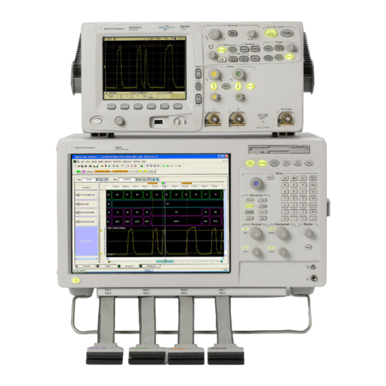
Page 19: To Make Time-Correlated Measurements With An Agilent Oscilloscope
To set up and use the time- correlated connection, choose Setup>Add External Scope... in the Agilent Logic Analyzer application. 16900 Series Logic Analysis Systems Installation Guide... - Page 20 Setting Up Hardware 16900 Series Logic Analysis Systems Installation Guide...
- Page 21 Agilent 16900 Series Logic Analysis Systems Installation Guide Installing Logic Analyzer Cards and Probes Software Requirements To connect probes To replace thumb screws on measurement modules To install, remove, or replace measurement modules 16962A Logic Analyzer (1-card module) 16962A Logic Analyzer (2-card, 3-card, and 4-card modules)
- Page 22 16760A Logic Analyzer (5-card module) 16752/51/50B/A, 16742/41/40A Logic Analyzer (1-card module) 16752/51/50B/A, 16742/41/40A Logic Analyzer (2-card module) 16752/51/50B/A, 16742/41/40A Logic Analyzer (3-card module) 16752/51/50B/A, 16742/41/40A Logic Analyzer (4-card module) 16752/51/50B/A, 16742/41/40A Logic Analyzer (5-card module) 16900 Series Logic Analysis Systems Installation Guide...
-
Page 23: Installing Logic Analyzer Cards And Probes
03.70 or higher 16951B 03.65 or higher 16950B 03.55 or higher 16950A 02.00 or higher 16911A, 16910A 02.00 or higher 16760A 03.20 or higher 16756/55/54/53A 02.00 or higher 16752/51/50B/A, 16742/41/40A 02.00 or higher 16900 Series Logic Analysis Systems Installation Guide... -
Page 24: To Connect Probes
Installing Logic Analyzer Cards and Probes The 16900 series of Logic Analysis systems with serial number of MY51420101 or higher N O T E require the Agilent Logic Analyzer software version 5.20 or later. These systems have the Windows 7 operating system installed. - Page 25 The 16900A/16902A logic analysis system comes with a set of 6 replacement thumb screws (16900- 68713), and the 16903A logic analysis system comes with a set of 2 replacement thumb screws (16903- 68713). 16900 Series Logic Analysis Systems Installation Guide...
-
Page 26: To Install, Remove, Or Replace Measurement Modules
C A U T I O N to eject the multiple cards simultaneously, otherwise, the flex cables and/or connectors could be damaged. 1 Power down the system and disconnect the power cable before installing, removing or replacing measurement modules. 16900 Series Logic Analysis Systems Installation Guide... - Page 27 The following figure shows a 6- card frame. The insertion/removal order would be the same for a 3- card frame. A single- module configuration can be installed in any available slot. 16900 Series Logic Analysis Systems Installation Guide...
- Page 28 6 Tighten the thumb screws until finger tight in the same order used in step 5 above. 7 For correct air circulation, install filler panels in all unused card slots. Correct air circulation keeps the instrument from overheating. Keep any extra filler panels for future use. 16900 Series Logic Analysis Systems Installation Guide...
- Page 29 Installing Logic Analyzer Cards and Probes 8 Refer to “First- Time Set Up” on page 77 to answer the Windows Welcome questions when you power up the logic analysis system for the first time. 16900 Series Logic Analysis Systems Installation Guide...
-
Page 30: 16962A Logic Analyzer (1-Card Module)
In a multi- card set, pods are indexed from the bottom up. Because clock signals can be input to any card in the set (on pod 1 or 3), cards do not have master and expander designations. 16900 Series Logic Analysis Systems Installation Guide... -
Page 31: 16962A Logic Analyzer (2-Card, 3-Card, And 4-Card Modules)
When removing cards that are connected together as multiple-card modules, be sure C A U T I O N to eject the multiple cards simultaneously, otherwise, the flex cables and/or connectors could be damaged. Flex Cables Flex Cables 16900 Series Logic Analysis Systems Installation Guide... - Page 32 2 Before inserting the next card into the desired slot, attach the flex cables to the under side of the card: a Flip up the connector actuator with your thumb or index finder. Do not use any type of tool to open the actuator. 16900 Series Logic Analysis Systems Installation Guide...
- Page 33 Place the flex cable into the connector, exposed conductive traces towards the card, so that the flex cable ears are secured by the connector guides. c Close the connector actuator. d Repeat for the opposite under- side flex cable and connector. 16900 Series Logic Analysis Systems Installation Guide...
- Page 34 Be careful not to bend the flex cables any more than is necessary to fit between the card connectors. c Close the connector actuator. d Repeat for the opposite top- side flex cable and connector. 5 Repeat steps 2- 4 for the remaining cards. 16900 Series Logic Analysis Systems Installation Guide...
- Page 35 Repeat the flex cable attachment steps, and check the continuity again. (Note that there is also a self test named “Resource Bus Connection Test” for verifying these connections when logic analyzer cards are installed.) 16900 Series Logic Analysis Systems Installation Guide...
- Page 36 Installing Logic Analyzer Cards and Probes While maintaining alignment with the cards as a set, insert them the rest of the way into the slots, seat them, lock the ejector tabs, and tighten the thumb screws. 16900 Series Logic Analysis Systems Installation Guide...
-
Page 37: 16960A Logic Analyzer (1-Card Module)
In a multi- card set, pods are indexed from the bottom up. Because clock signals can be input to any card in the set (on pod 1 or 3), cards do not have master and expander designations. 16900 Series Logic Analysis Systems Installation Guide... -
Page 38: 16960A Logic Analyzer (2-Card, 3-Card, And 4-Card Modules)
When removing cards that are connected together as multiple-card modules, be sure C A U T I O N to eject the multiple cards simultaneously, otherwise, the flex cables and/or connectors could be damaged. Flex Cables Flex Cables 16900 Series Logic Analysis Systems Installation Guide... - Page 39 2 Before inserting the next card into the desired slot, attach the flex cables to the under side of the card: a Flip up the connector actuator with your thumb or index finder. Do not use any type of tool to open the actuator. 16900 Series Logic Analysis Systems Installation Guide...
- Page 40 Place the flex cable into the connector, exposed conductive traces towards the card, so that the flex cable ears are secured by the connector guides. c Close the connector actuator. d Repeat for the opposite under- side flex cable and connector. 16900 Series Logic Analysis Systems Installation Guide...
- Page 41 Be careful not to bend the flex cables any more than is necessary to fit between the card connectors. c Close the connector actuator. d Repeat for the opposite top- side flex cable and connector. 5 Repeat steps 2- 4 for the remaining cards. 16900 Series Logic Analysis Systems Installation Guide...
- Page 42 7 While maintaining alignment with the cards as a set, insert them the rest of the way into the slots, seat them, lock the ejector tabs, and tighten the thumb screws. 16900 Series Logic Analysis Systems Installation Guide...
-
Page 43: 16951/50B Logic Analyzer (1-Card Module)
The order of pods on the card’s rear panel is: Pod 4 Pod 3 Pod 2 Pod 1 In a multi- card set, pods are indexed starting with the master card, then with the expander cards from the bottom up. 16900 Series Logic Analysis Systems Installation Guide... -
Page 44: 16951/50B Logic Analyzer (2-Card Module)
The 16950B logic analyzer module must only be combined with another 16950B module. N O T E Likewise, the 16951B logic analyzer module must only be combined with another 16951B module. A 16950B combined set will default to the lowest memory depth in the set. 16900 Series Logic Analysis Systems Installation Guide... -
Page 45: 16951/50B Logic Analyzer (3-Card Module)
The 16950B logic analyzer module must only be combined with other 16950B modules. N O T E Likewise, the 16951B logic analyzer module must only be combined other 16951B modules. A 16950B combined set will default to the lowest memory depth in the set. 16900 Series Logic Analysis Systems Installation Guide... -
Page 46: 16951/50B Logic Analyzer (4-Card Module)
The 16950B logic analyzer module must only be combined with other 16950B modules. N O T E Likewise, the 16951B logic analyzer module must only be combined other 16951B modules. A 16950B combined set will default to the lowest memory depth in the set. 16900 Series Logic Analysis Systems Installation Guide... -
Page 47: 16951/50B Logic Analyzer (5-Card Module)
The 16950B logic analyzer module must only be combined with other 16950B modules. N O T E Likewise, the 16951B logic analyzer module must only be combined other 16951B modules. A 16950B combined set will default to the lowest memory depth in the set. 16900 Series Logic Analysis Systems Installation Guide... -
Page 48: 16950A, 16756/55/54/53A Logic Analyzer (1-Card Module)
The order of pods on the card’s rear panel is: Pod 4 Pod 3 Pod 2 Pod 1 In a multi- card set, pods are indexed starting with the master card, then with the expander cards from the bottom up. 16900 Series Logic Analysis Systems Installation Guide... -
Page 49: 16950A, 16756/55/54/53A Logic Analyzer (2-Card Module)
You can combine any combination of 16753A, 16754A, 16755A, 16756A, and 16950A logic N O T E analyzer modules in a 2-card set. The combined set will default to the lowest memory depth in the set. 16900 Series Logic Analysis Systems Installation Guide... -
Page 50: 16950A, 16756/55/54/53A Logic Analyzer (3-Card Module)
You can combine any combination of 16753A, 16754A, 16755A, 16756A, and 16950A logic N O T E analyzer modules in a 3-card set. The combined set will default to the lowest memory depth in the set. 16900 Series Logic Analysis Systems Installation Guide... -
Page 51: 16950A, 16756/55/54/53A Logic Analyzer (4-Card Module)
You can combine any combination of 16753A, 16754A, 16755A, 16756A, and 16950A logic N O T E analyzer modules in a 4-card set. The combined set will default to the lowest memory depth in the set. 16900 Series Logic Analysis Systems Installation Guide... -
Page 52: 16950A, 16756/55/54/53A Logic Analyzer (5-Card Module)
You can combine any combination of 16753A, 16754A, 16755A, 16756A, and 16950A logic N O T E analyzer modules in a 5-card set. The combined set will default to the lowest memory depth in the set. 16900 Series Logic Analysis Systems Installation Guide... -
Page 53: 16911A/10A Logic Analyzer (1-Card Module)
The order of pods on the 16911A logic analyzer card’s rear panel is: Pods 3 and 4 Pods 1 and 2 In a multi- card set, pods are indexed starting with the master card, then with the expander cards from the bottom up. 16900 Series Logic Analysis Systems Installation Guide... -
Page 54: 16911A/10A Logic Analyzer (2-Card Module)
You can combine the same model numbers only (16910A in a 2-card set or 16911A in a N O T E 2-card set). The combined set will default to the lowest state speed and memory depth in the set. 16900 Series Logic Analysis Systems Installation Guide... -
Page 55: 16911A/10A Logic Analyzer (3-Card Module)
You can combine the same model numbers only (16910A in a 3-card set or 16911A in a N O T E 3-card set). The combined set will default to the lowest state speed and memory depth in the set. 16900 Series Logic Analysis Systems Installation Guide... -
Page 56: 16911A/10A Logic Analyzer (4-Card Module)
You can combine the same model numbers only (16910A in a 4-card set or 16911A in a N O T E 4-card set). The combined set will default to the lowest state speed and memory depth in the set. 16900 Series Logic Analysis Systems Installation Guide... -
Page 57: 16911A/10A Logic Analyzer (5-Card Module)
You can combine the same model numbers only (16910A in a 5-card set or 16911A in a N O T E 5-card set). The combined set will default to the lowest state speed and memory depth in the set. 16900 Series Logic Analysis Systems Installation Guide... -
Page 58: 16760A Logic Analyzer (1-Card Module)
The order of pods on the card’s rear panel is: Pod 2 Pod 1 In a multi- card set, pods are indexed starting with the master card, then with the expander cards from the bottom up. 16900 Series Logic Analysis Systems Installation Guide... -
Page 59: 16760A Logic Analyzer (2-Card Module)
Use two 2 x 10 cables and two 2 x 40 cables (in the accessory pouch) to connect the modules. Turn off the mainframe power before removing, replacing, or installing modules following N O T E the procedures on page 16900 Series Logic Analysis Systems Installation Guide... -
Page 60: 16760A Logic Analyzer (3-Card Module)
Use three 2 x 10 cables and four 2 x 40 cables (in the accessory pouch) to connect the modules. Turn off the mainframe power before removing, replacing, or installing modules following N O T E the procedures on page 16900 Series Logic Analysis Systems Installation Guide... -
Page 61: 16760A Logic Analyzer (4-Card Module)
Use four 2 x 10 cables and six 2 x 40 cables (in the accessory pouch) to connect the modules. Turn off the mainframe power before removing, replacing, or installing modules following N O T E the procedures on page 16900 Series Logic Analysis Systems Installation Guide... -
Page 62: 16760A Logic Analyzer (5-Card Module)
Use five 2 x 10 cables and eight 2 x 40 cables (in the accessory pouch) to connect the modules. Turn off the mainframe power before removing, replacing, or installing modules following N O T E the procedures on page 16900 Series Logic Analysis Systems Installation Guide... -
Page 63: 16752/51/50B/A, 16742/41/40A Logic Analyzer (1-Card Module)
The order of pods on the card’s rear panel is: Pods 3 and 4 Pods 1 and 2 In a multi- card set, pods are indexed starting with the master card, then with the expander cards from the bottom up. 16900 Series Logic Analysis Systems Installation Guide... -
Page 64: 16752/51/50B/A, 16742/41/40A Logic Analyzer (2-Card Module)
Measurement modules with different model numbers cannot be connected together in N O T E multi-card modules. However, the 16750A may be connected to a 16750B; the 16751A may be connected to a 16751B; the 16752A may be connected to a 16752B. 16900 Series Logic Analysis Systems Installation Guide... -
Page 65: 16752/51/50B/A, 16742/41/40A Logic Analyzer (3-Card Module)
Measurement modules with different model numbers cannot be connected together in N O T E multi-card modules. However, the 16750A may be connected to a 16750B; the 16751A may be connected to a 16751B; the 16752A may be connected to a 16752B. 16900 Series Logic Analysis Systems Installation Guide... -
Page 66: 16752/51/50B/A, 16742/41/40A Logic Analyzer (4-Card Module)
Measurement modules with different model numbers cannot be connected together in N O T E multi-card modules. However, the 16750A may be connected to a 16750B; the 16751A may be connected to a 16751B; the 16752A may be connected to a 16752B. 16900 Series Logic Analysis Systems Installation Guide... -
Page 67: 16752/51/50B/A, 16742/41/40A Logic Analyzer (5-Card Module)
Measurement modules with different model numbers cannot be connected together in N O T E multi-card modules. However, the 16750A may be connected to a 16750B; the 16751A may be connected to a 16751B; the 16752A may be connected to a 16752B. 16900 Series Logic Analysis Systems Installation Guide... - Page 68 Installing Logic Analyzer Cards and Probes 16900 Series Logic Analysis Systems Installation Guide...
- Page 69 Agilent 16900 Series Logic Analysis Systems Installation Guide Installing Pattern Generator Cards Software Requirements 16720A Pattern Generator (1-card module) 16720A Pattern Generator (2-card module) 16720A Pattern Generator (3-card module) 16720A Pattern Generator (4-card module) 16720A Pattern Generator (5-card module) ...
-
Page 70: Installing Pattern Generator Cards
23. For information on updating your logic analysis system software go to “To install software” on page 103. Table 4 Software Version Required, Pattern Generator Modules Model Number Software Version 16720A 03.00 or higher 16900 Series Logic Analysis Systems Installation Guide... -
Page 71: 16720A Pattern Generator (1-Card Module)
The order of pods on the card’s rear panel is: Pod 6 Pod 4 Clk Pod Pod 5 Pod 3 Pod 2 Pod 1 In a multi- card set, pods are indexed from the bottom up. 16900 Series Logic Analysis Systems Installation Guide... -
Page 72: 16720A Pattern Generator (2-Card Module)
Turn off the mainframe power before removing, replacing, or installing modules. For N O T E instructions on installing modules into the logic analysis system frame, refer to page 2x10 Cable Expander Master 16900 Series Logic Analysis Systems Installation Guide... -
Page 73: 16720A Pattern Generator (3-Card Module)
Turn off the mainframe power before removing, replacing, or installing modules. For N O T E instructions on installing modules into the logic analysis system frame, refer to page 2x10 Cable Expander Master Expander 16900 Series Logic Analysis Systems Installation Guide... -
Page 74: 16720A Pattern Generator (4-Card Module)
Expander Card to the Master Card first. Then cable the upper two Expander Cards to the Master Card. 3 Gently slide the cabled assembly fully into the frame and tighten the thumb screws. 2x10 Cable Expander Expander Master Expander 16900 Series Logic Analysis Systems Installation Guide... -
Page 75: 16720A Pattern Generator (5-Card Module)
Expander Cards to the Master Card first. Then cable the upper two Expanders to the Master Card. 3 Gently slide the cabled assembly fully into the frame and tighten the thumb screws. 2x10 Cable Expander Expander Master Expander Expander 16900 Series Logic Analysis Systems Installation Guide... - Page 76 Installing Pattern Generator Cards 16900 Series Logic Analysis Systems Installation Guide...
- Page 77 Agilent 16900 Series Logic Analysis Systems Installation Guide First-Time Set Up First-Time Set Up Considerations First-Time Set Up On Legacy 16900 Series Systems With Windows XP Installation First-Time Set Up On 16900 Series Systems with Windows 7 Installation Additional First Time Setup Steps...
-
Page 78: First-Time Set Up
• Methodology for assigning IP addresses at your site (for example, DHCP). • Domain Name Service (DNS). This can also be obtained automatically. • Other network information that may be readily available from your network administrator. 16900 Series Logic Analysis Systems Installation Guide... -
Page 79: First-Time Set Up On Legacy 16900 Series Systems With Windows Xp Installation
First-Time Set Up First-Time Set Up On Legacy 16900 Series Systems With Windows XP Installation The legacy 16900 series logic analysis systems are shipped with Windows ® XP installation. The first time you turn on these systems, the Windows Welcome session starts. Your logic analyzer configuration and the answers to the Windows Welcome questions are affected by how you choose to use the logic analyzer. -
Page 80: If Expected Windows Welcome Questions Do Not Appear
Windows unable to later. determine LAN connectivity. Ready to register with The legacy 16900 series of Logic Analysis systems have Windows XP already enabled to Microsoft run. This registration is to allow Microsoft to contact you. Who will use this computer? For All: Entering names here lets multiple users use the logic analyzer with administrator permissions. -
Page 81: First-Time Set Up On 16900 Series Systems With Windows 7 Installation
First-Time Set Up On 16900 Series Systems with Windows 7 Installation The first time you turn on a 16900 series logic analysis system that is shipped with Windows 7 installation, you are automatically logged on to the system using the Administrator account and the Windows 7 desktop is displayed. - Page 82 Register with Microsoft The 16900 series of Logic Analysis systems with serial number of MY51420101 or higher have the Windows 7 operating system already enabled to run. This registration is to allow Microsoft to contact you.
-
Page 83: Additional First Time Setup Steps
Protecting the Instrument’s Operating System Microsoft recommends the following three steps to ensure the instrument's PC is protected. 1 Use an internet firewall. 2 Get operating system updates. 3 Use up- to- date antivirus software. 16900 Series Logic Analysis Systems Installation Guide... - Page 84 First-Time Set Up 16900 Series Logic Analysis Systems Installation Guide...
-
Page 85: Setting Up Multiframe Configurations
Agilent 16900 Series Logic Analysis Systems Installation Guide Setting Up Multiframe Configurations Setting Up Simple Multiframe Configurations Setting Up a Performance Multiframe Configuration Other Multiframe Configuration Notes If you need to make time- correlated measurements with more logic analysis channels than can be installed into a single logic analysis system... -
Page 86: Setting Up Simple Multiframe Configurations
Simple Multiframe Configuration using an Intranet 16900 Series Logic Analysis Systems Installation Guide... -
Page 87: Simple Multiframe Configuration Using An Isolated Router
In the simple multiframe configuration using an isolated router, all the systems are connected to the common network using their LAN port. Rules for Simple Multiframe Configurations In addition to the earlier guidelines on page 16900 Series Logic Analysis Systems Installation Guide... -
Page 88: Creating Simple Multiframe Configurations
It is highly recommended that the network and all systems be configured to allow DHCP services to manage IP addressing. 2 Power off all logic analysis system frames. 3 Connect multiframe cable(s) between the chassis as shown. 16900 Series Logic Analysis Systems Installation Guide... - Page 89 To configure this, remove any shortcuts to the application from the Windows Start > All Programs > startup menu. Depending on your multiframe connection topology, it may take several seconds for the N O T E Agilent Logic Analyzer application to start. 16900 Series Logic Analysis Systems Installation Guide...
- Page 90 Power up the systems as per the startup sequence described in Step e When all systems are ready, start the Agilent Logic Analyzer application on the system from which you want to control the multiframe setup. Wait for the application to stabilize. 16900 Series Logic Analysis Systems Installation Guide...
-
Page 91: Remotely Controlling Simple Multiframe Systems
With this option: • Your performance may vary because analyzer data from all logic analysis systems must be sent over LAN to your locally running application. 16900 Series Logic Analysis Systems Installation Guide... -
Page 92: Setting Up A Performance Multiframe Configuration
Setting Up Multiframe Configurations Setting Up a Performance Multiframe Configuration 16900 Series Logic Analysis Systems Installation Guide... -
Page 93: Rules For Performance Multiframe Configurations
Make sure all frames are connected to the common network and are recognized before continuing. • Because the Agilent Logic Analyzer application runs on the performance PC connected remotely to any frames, the frames' front panel knobs and buttons are not functional. 16900 Series Logic Analysis Systems Installation Guide... - Page 94 Agilent Notification Center tray icon of when the system is ready. So an appropriate delay will be required before proceeding with the next system. 16900 Series Logic Analysis Systems Installation Guide...
- Page 95 If the application starts without errors, and the multiframe system appears in the Overview window, you are almost ready to use the multiframe system. Exit the application, and continue on step 10. 16900 Series Logic Analysis Systems Installation Guide...
- Page 96 11 If you have trouble connecting to the frame, check these potential problems: a Verify that the multiframe logic analysis system appears in the Overview window when running the Agilent Logic Analyzer 16900 Series Logic Analysis Systems Installation Guide...
-
Page 97: Remotely Controlling A Performance Multiframe System
• Use one of the remote window utilities to remotely control the performance PC. Choose from Remote Desktop, RealVNC, or NetOp. You will need to set up this service on your performance PC and your local 16900 Series Logic Analysis Systems Installation Guide... -
Page 98: Other Multiframe Configuration Notes
• In the performance multiframe configuration, install node- locked licenses on the performance PC. If you are using floating licenses, the license server needs to be accessible from the frame or performance PC on which the Agilent Logic Analyzer application runs. 16900 Series Logic Analysis Systems Installation Guide... - Page 99 Agilent 16900 Series Logic Analysis Systems Installation Guide Using and Updating the Logic Analysis System To locate information on using the logic analyzer To locate specifications and characteristics To perform backups To install software To change network settings To change Windows Firewall settings...
-
Page 100: Using And Updating The Logic Analysis System
The Quick Start for 16700 Series Users provides experienced users of the 16700 Series logic analysis system with tips on how to quickly become productive with the new 16900 Series logic analysis system. 16900 Series Logic Analysis Systems Installation Guide... -
Page 101: To Locate Specifications And Characteristics
Using and Updating the Logic Analysis System To locate specifications and characteristics Electrical and Operating Environment Characteristics The following operating characteristics are not specifications, but are typical operating characteristics for the Agilent 16900 Series logic analysis systems. Electrical Characteristics Power... -
Page 102: More Specifications And Characteristics
More Specifications and Characteristics More specifications and characteristics for your instrument and measurement modules are in the online help. To find them go to: 1 Click Help>Help Topics. 2 Click Reference>Specifications and Characteristics. 16900 Series Logic Analysis Systems Installation Guide... -
Page 103: To Perform Backups
To upgrade/reinstall the logic analyzer software or to install the logic analyzer software onto your PC for offline processing: • On legacy 16900 Series logic analysis systems that were shipped with an application CD, insert the application CD and click INSTALL PRODUCTS>Install Logic Analyzer. -
Page 104: Optional Products
Computer Name tab and click Change. • To change network connection properties, click Start>Control Panel>Network and Sharing Center. Select the connection you want to change and then set the properties of this connection. 16900 Series Logic Analysis Systems Installation Guide... - Page 105 Using and Updating the Logic Analysis System For more information on changing network settings, refer to the Windows 7 online help. 16900 Series Logic Analysis Systems Installation Guide...
-
Page 106: To Change Windows Firewall Settings
Using and Updating the Logic Analysis System To change Windows Firewall settings When 16900 Series logic analysis systems are shipped from the factory, the Windows Firewall is enabled and set up with the exceptions required by the logic analysis system. - Page 107 To change firewall settings on Windows 7 to give other applications/ports access: 1 From the Windows Start menu, choose Start>Control Panel. 2 In the Control Panel window, click Windows Firewall. 3 Click the Allow a program or a feature through Windows firewall link. 16900 Series Logic Analysis Systems Installation Guide...
- Page 108 Standard for when the computer has workgroup membership. If you change the type of membership, any changes you made to the Windows Firewall settings will have to be made again. 16900 Series Logic Analysis Systems Installation Guide...
-
Page 109: To Restore The Logic Analysis System Firewall Defaults
Using and Updating the Logic Analysis System To restore the logic analysis system firewall defaults On legacy 16900 logic analysis systems 1 From the Windows Start menu, choose Start>Control Panel. 2 In the Control Panel window, open Windows Firewall. 16900 Series Logic Analysis Systems Installation Guide... - Page 110 Analyzer software and Windows XP installation, then restore the firewall defaults by following the steps 1 to 6 in the procedure described in previous section. After that, uninstall and then reinstall the Logic Analyzer software from www.agilent.com/find/la- sw- download. 16900 Series Logic Analysis Systems Installation Guide...
- Page 111 Note that there are separate Windows Firewall profiles: Domain for when the computer has N O T E domain membership, and Standard for when the computer has workgroup membership. When you restore the logic analysis system firewall defaults, the defaults for both profiles are restored. 16900 Series Logic Analysis Systems Installation Guide...
-
Page 112: To Power Off The System
Clicking the 'yes' button results in the above events. Clicking 'no' will prevent the shutdown and not answering the dialog box (neither clicking "Yes" or "No") will have no effect. Further short presses on the power button will have no effect. 16900 Series Logic Analysis Systems Installation Guide... -
Page 113: Using A Long Press Of The Power Button
Unplugging power or a power loss is similar to the long press of the power button with one exception: • When the system is plugged back in, it will power up and boot into Windows. 16900 Series Logic Analysis Systems Installation Guide... -
Page 114: To Remove The Hard Disk Drive (16902B)
112) and disconnect the power cable before removing the hard disk drive. 2 Loosen the thumb screw that holds the hard disk drive in place. 3 Pull the drive tray out to remove the disk drive. Thumb Screw 16900 Series Logic Analysis Systems Installation Guide... -
Page 115: To Install Interface Cards (16900A, 16902A, 16902B, Or 16903A)
When reinstalling the handle assembly, ensure that the screws are torqued to 2.372 C A U T I O N Newton meters (21 inch pounds) so that they do not work themselves loose. 16900 Series Logic Analysis Systems Installation Guide... - Page 116 Using and Updating the Logic Analysis System 3 Disconnect cables from the module interface board. a If you have a 16900A, 16902A: b If you have a 16903A or 16902B: 16900 Series Logic Analysis Systems Installation Guide...
- Page 117 Using and Updating the Logic Analysis System 4 Remove screws from the back of the CPU tray using a Torx T- 10 screwdriver. 16900 Series Logic Analysis Systems Installation Guide...
- Page 118 CPU board from the module interface board then slide the tray out being careful not to catch the loose cables on anything. b If you have a 16902B or 16903A, slide the tray out being careful not to catch the loose cables on anything. 16900 Series Logic Analysis Systems Installation Guide...
- Page 119 First align the posts and holes then use the tray levers to push the tray fully into place (see the figure in step 5a). b If you have a 16903A, slide the CPU tray into the frame. 16900 Series Logic Analysis Systems Installation Guide...
-
Page 120: Gbit Lan Card
(Option 014) it will already be installed. If you order the 1 Gbit LAN card separately (as model E5860A), you need to install the card following the instructions beginning on page 115. To order a 1 Gbit LAN card go to: http://www.agilent.com/find/contactus 16900 Series Logic Analysis Systems Installation Guide... -
Page 121: To Install Interface Cards (16901A)
The following instructions show you how to properly remove the 16901A logic analysis system cover, install interface cards, and replace the cover. 1 Power down the system and disconnect the power cable before installing interface cards. 16900 Series Logic Analysis Systems Installation Guide... - Page 122 Optional: Removing the shroud may make it easier to remove and replace the cover. In this case, remove 4 T10 screws; then, remove the shroud. c Slide the cover back to remove. 16900 Series Logic Analysis Systems Installation Guide...
- Page 123 When reinstalling the handle assembly, ensure that the screws are torqued to 2.372 C A U T I O N Newton meters (21 inch pounds) so that they do not work themselves loose. 16900 Series Logic Analysis Systems Installation Guide...
-
Page 124: To Replace The Cpu Battery
3 Using a 1/8 inch flat- blade screwdriver, gently pry the battery from the battery receptacle. 4 Insert a new battery (CR2032 3V lithium) into the battery receptacle. 5 Put the frame back together by reversing the “access the motherboard” steps used earlier. 16900 Series Logic Analysis Systems Installation Guide... - Page 125 Agilent 16900 Series Logic Analysis Systems Installation Guide Solving Problems Running Self-Tests If the logic analysis system powers itself down If the Power LEDs do not come on If you get a registry error and the system won’t boot If you can’t write/read CDs...
-
Page 126: Solving Problems
Solving Problems Running Self-Tests 1 In the Agilent logic analyzer application, click Help>Self Test. 2 In the analysis system Self Test dialog, double click on the test you want to run. 16900 Series Logic Analysis Systems Installation Guide... -
Page 127: If The Logic Analysis System Powers Itself Down
• Green — front power supply failure. • Yellow — side power supply failure. • Red — fan failure or ‘overtemp’. For any of the above conditions, go to http://www.agilent.com/find/contactus to contact your local service representative. 16900 Series Logic Analysis Systems Installation Guide... -
Page 128: All 16900 Series Logic Analysis Systems
This process overwrites all the user data and restores the system back to the original condition in which it was shipped. Refer to the topic “On a 16900 Series Logic Analysis System with Windows 7 Installation” on page 133 to know more about this process. -
Page 129: If You Can't Write/Read Cds
• Can read DVD- RAM, DVD- R and DVD- RW. • Buffer Under Run Protection. • Writing Method: • Disc at Once. • Session at Once. • Track at Once. • Multi- Session. • Fixed/Variable Packet Writing. 16900 Series Logic Analysis Systems Installation Guide... -
Page 130: If There Are Multiframe Connection Problems
• One or more of the frames is not completely initialized yet... Please wait a few seconds. To check the Jumbo Frames setting: 1 Choose Start>Control Panel. In the Control Panel window, open Network Connections. 16900 Series Logic Analysis Systems Installation Guide... - Page 131 Solving Problems 2 Right- click on the LAN connection and select Properties. 3 Click on Configure and then select the Advanced tab. 4 Select Jumbo Frames and the Value. 16900 Series Logic Analysis Systems Installation Guide...
-
Page 132: If There Are Network Connection Problems
In this case, you need to add the computer (logic analysis system) to the domain. 16900 Series Logic Analysis Systems Installation Guide... -
Page 133: Using The System Recovery Software
On a Legacy 16900 Series Logic Analysis System with Windows XP installation The legacy 16900 series of Logic Analysis systems have the Windows XP operating system installed. These systems also have the Agilent Logic Analyzer software preinstalled. - Page 134 This is the normal startup of the system. • Agilent Recovery system - You should select this option when you want to restore/repair your Logic Analysis system software by running the Agilent recovery process. 16900 Series Logic Analysis Systems Installation Guide...
- Page 135 3 to view a document that provides information on the recovery process. • 4 to repair the Logic Analysis system hard disk drive. • 5 to exit the recovery process and restart the Logic Analysis system in the normal mode. 16900 Series Logic Analysis Systems Installation Guide...
- Page 136 C: drive. If you want to save your data to a CD or to another machine before you proceed further, then exit the recovery process and save your data. Else, click OK to proceed with the recovery process. The recovery process starts. 16900 Series Logic Analysis Systems Installation Guide...
- Page 137 6 The Windows Boot Manager screen is displayed with Microsoft Windows 7 as the default selection. The system automatically starts with this default selection. Alternatively, you can press Enter to proceed with the default selection. 16900 Series Logic Analysis Systems Installation Guide...
-
Page 138: Contacting Agilent Service/Support
Agilent. Alternatively, you can contact your nearest Agilent sales/service office. To locate a sales or service office, go to www.agilent.com/find/contactus. Contacting Agilent Service/Support To locate a sales or service office near you, go to: http://www.agilent.com/find/contactus 16900 Series Logic Analysis Systems Installation Guide... -
Page 139: Safety Notices
Agilent 16900 Series Logic Analysis Systems Installation Guide Safety Notices This apparatus has been designed and tested in accordance with IEC Publication 1010, Safety Requirements for Measuring Apparatus, and has been supplied in a safe condition. This is a Safety Class I instrument (provided with terminal for protective earthing). -
Page 140: To Clean The Instrument
Instruction manual symbol: the product is marked with this symbol when it is necessary for you to refer to the instruction manual in order to protect against damage to the product. Hazardous voltage symbol. 16900 Series Logic Analysis Systems Installation Guide... - Page 141 Safety Notices Earth terminal symbol: Used to indicate a circuit common connected to grounded chassis. 16900 Series Logic Analysis Systems Installation Guide...
- Page 142 Safety Notices 16900 Series Logic Analysis Systems Installation Guide...
-
Page 143: Index
ICMP settings, cross-triggering, install interface cards, 115, backup, measurement modules, software, debugging network, interface cards, 115, disk internet, clean/reformat, cable inverse assemblers, read error, flying lead, display resolution, multiframe, domain, 78, cards, measurement, DVD-ROM, 16900 Series Logic Analysis Systems Installation Guide... - Page 144 CPU tray, 115, touch off button, connection decision, filler panels, Trigger In, 19, 98, debugging, removing Trigger Out, 19, network connection problems, cover, network settings, replace CPU battery, restoring system, update software, 16900 Series Logic Analysis Systems Installation Guide...
- Page 145 Index version requirements, 23, virus software, 17, warnings, web address probes, service/support, windows power problems, updates, welcome, welcome questions, Windows Boot Manager, Windows Firewall settings changing, workgroup, changing, 16900 Series Logic Analysis Systems Installation Guide...
- Page 146 Index 16900 Series Logic Analysis Systems Installation Guide...