
Related Manuals for Endress+Hauser FEC 12


Summary of Contents for Endress+Hauser FEC 12
- Page 1 Electronic insert BA 148F/00/en/07.95 (b) Software Version 1.x Part No. 016700-1000 FEC 12 with HART Protocol Level Measurement Operating Instructions Endress Hauser The Power of Know How...
-
Page 2: Short Instructions
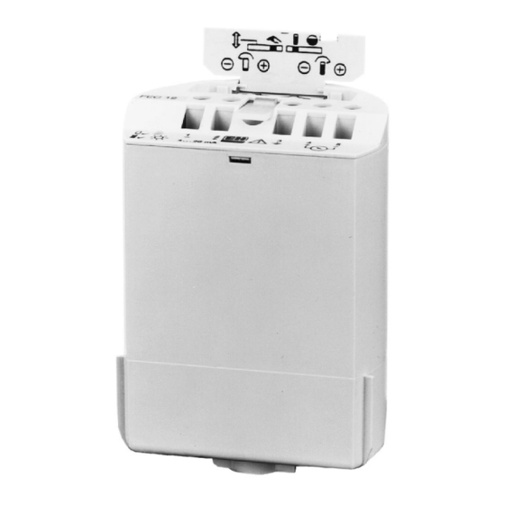
A detailed description of calibration and operation is given in Sections 3 - 5. Abb. 1 Short instructions for calibrating the FEC 12 electronic insert using its own operating elements lid with short instructions... -
Page 3: Table Of Contents
6.6 Transmitting All Settings In addition to these operating instructions, the following documentation is also Supplementary available on the use of the FEC 12 electronic insert: documentation • Technical Information TI 242F/00/e: Multicap Probes DC ... E • Technical Information TI 243F/00/e: Multicap Probes DC ... A •... -
Page 4: Notes On Safety
Notes on Safety Approved usage The electronic insert FEC 12 may be used for level measurement in connection with capacitive Multicap probes only. It has been designed to operate safely in accordance with current technical and safety standards and must be installed by qualified personnel according to the instructions in this manual. -
Page 5: Introduction
A pre-stored linearisation program also allows volumes to be measured in horizontal cylinders. The FEC 12 electronic insert is installed in the housing of the Multicap probe. It can be used for applications in explosion hazardous areas. -
Page 6: Installation
Insert the power cable through the cable Fig. 3 Connecting the entry on the probe housing. Unscreened FEC 12 electronic insert to the or general purpose multi-core cable can power supply be used as the connecting cable. If strong electromagnetic interference FEC 12 occurs due to, e.g. -
Page 7: Technical Data
Electronic insert FEC 12 (HART) Installation A load should be connected into the power cable when connecting a handheld Load for handheld terminal. The handheld terminal can now be connected at any point along the power terminal cable for communication with the electronic insert. The size of the load is given in the following table. -
Page 8: Operating Elements
FEC 12 operating elements. If linearisation at the FEC 12 is required, then one of two stored linearisation modes in the electronic insert is activated (vertical vessel with linear characteristics or horizontal cylinder) at the righthand switch. -
Page 9: Hart Communicator Dxr 275
"Online" 3.3 HART Menu Structure All parameters of the FEC 12 can be addressed by the menu structure using the handheld terminal. The following diagram shows the menu structure of the HART protocol for the FEC 12 electronic insert. Each field in the menu structure can be selected using the arrow or numeric keys on the handheld terminal. -
Page 10: Calibrating For Level Measurement
A complete recalibration is not then required (see also Section 6). 4.1 Basic Calibration at the FEC 12 Electronic Insert The following entries are required for basic calibration of the electronic insert: •... - Page 11 Electronic insert FEC 12 (HART) Calibrating Two types of linearisation can be selected: Selecting linearisation • Vessel characteristics as linear • Vessel characteristics as a horizontal cylinder Use the lefthand switch to select whether linearisation is to be carried out at the electronic insert or by the handheld terminal.
- Page 12 Calibrating Electronic insert FEC 12 (HART) Alternative procedure: The level of the vessel must be known as accurately as possible and should be as calibration with the high as possible. A level which is too low reduces the accuracy of the upper point vessel almost full (corresponding to a full vessel).
-
Page 13: Basic Settings Using The Hart Communicator Dxr 275
Calibrating 4.2 Basic Settings using the HART Communicator DXR 275 The FEC 12 allows calibration in % only. A remote calibration from the handheld allows, e.g. technical units to be displayed. If a recalibration is to be carried out, then a reset should be done first. -
Page 14: Basic Calibration At The Fec
Two vessel characteristics are available: linear or horizontal cylinder Note! • The switch on the left on the FEC 12 electronic insert must be moved to the left so that linearisation can be carried out remotely with the handheld terminal. - Page 15 Electronic insert FEC 12 (HART) Calibrating The output damping is set in the factory at 1 s and affects the speed at which the Output damping current output responds to a change in level. When there is a sudden jump from empty to full in the vessel, after 1 s the current display reaches 63% or 14.08 mA of...
-
Page 16: Entries For The Measuring Point
Entries for the Measuring Point Electronic insert FEC 12 (HART) Entries for the Measuring Point 5.1 Locking/Unlocking Parameters Locking The parameters can be locked from the handheld terminal by entering a code number between 1 and 11 or between 13 and 9998: all settings in the electronic insert are protected from being altered. -
Page 17: Diagnosis And Troubleshooting
The following response is set in the factory: Output on alarm If the FEC 12 detects a fault, then the current output is set to 22 mA (=110 %) to enable process control systems to, e.g. assume a response. If no alarm indication is to be given on an alarm, then "... - Page 18 Diagnosis and Troubleshooting Electronic insert FEC 12 (HART) Simulation for level Enter the level value to be simulated. The appropriate current is given by the electronic insert. Step Entry Cursor in Display at Significance Service/Simulation SERVICE/SIMULATION Simulation for level SIM. LEVEL Actual measured value is displayed e.g.
-
Page 19: Description Of Fault Responses, Error Messages
The current lies outside the permitted range (4.0 ... 20 mA or 3.8 ... 20 mA). It has no relationship to the measured value. 6.4 Replacing the FEC 12 Electronic Insert Note! If you want to transmit the settings of the old electronic insert into a new electronic insert, then please note the following section. -
Page 20: Transmitting All Settings
HART Communicator handheld terminal. The procedure begins with an upload with the data from the old FEC 12 to the handheld terminal. Once the upload has been completed, a download is is made and all data are transmitted from the handheld terminal to the new FEC 12. - Page 21 Electronic insert FEC 12 (HART) Diagnosis and Troubleshooting You must first move to the "Offline Configure" menu before carrying out a download. Download Step Entry Display Significance MATRIX GROUP SEL. Online Offline Offline Configure New Device or Last Device The data you wish to be transmit to another electronic insert can be collected in this menu.
- Page 22 Belorgsintez Canada Poland Singapore Minsk Endress+Hauser Ltd. Endress+Hauser Polska Sp. z o.o. Endress+Hauser (S.E.A.) Pte., Ltd. Tel. (01 72) 508473, Fax (01 72) 508583 Burlington, Ontario Warszawy Singapore Tel. (9 05) 6 81 92 92, Fax (9 05) 6 81 94 44 Tel.