Siemens SENTRON 3WA System Manual
Hide thumbs
Also See for SENTRON 3WA:
- Operating instructions manual (14 pages) ,
- Manual (50 pages) ,
- Operating instructions manual (12 pages)
Table of Contents
Advertisement
Advertisement
Table of Contents

Related Manuals for Siemens SENTRON 3WA


Summary of Contents for Siemens SENTRON 3WA
- Page 3 Introduction System description SENTRON Status of the circuit breaker Parameterization and remote control Protection devices 3WA Air Circuit Breaker Communication Modbus TCP PROFINET IO System Manual Disposal ESD guidelines List of abbreviations 11/2021 92310000004-02...
- Page 4 Note the following: WARNING Siemens products may only be used for the applications described in the catalog and in the relevant technical documentation. If products and components from other manufacturers are used, these must be recommended or approved by Siemens. Proper transport, storage, installation, assembly, commissioning, operation and maintenance are required to ensure that the products operate safely and without any problems.
-
Page 5: Table Of Contents
Table of contents Introduction ............................5 Scope of validity of this document..................5 Target readers of this documentation ................... 5 Technical Support ........................ 5 Reference documents ......................5 Advanced training courses ....................6 Safety instructions ....................... 7 1.6.1 Safety regulations ........................ 7 1.6.2 Security information ...................... - Page 6 Table of contents Parameterization of ground-fault protection (GF) ............... 34 Modbus TCP ............................35 General ..........................35 Addressing ........................35 Function codes, metering values and parameters ............... 36 5.3.1 Function codes ........................36 5.3.2 Metering values, parameters and commands ..............36 5.3.2.1 Reading metering values and parameters ................
-
Page 7: Introduction
The information contained in this manual is provided for the benefit of: • Users • Programmers Technical Support You can find further support on the Internet at: TechnicalSupport (https://www.siemens.com/support-request) Reference documents For more information, refer to the following documents: Title Part number... -
Page 8: Advanced Training Courses
Distribution in Low-Voltage Networks), substantially extended and revised edition 1997 Siemens: Residual Current Protective Devices, Low-Voltage Circuit Protec- E10003-E38-9T-B3011 tion Technology Primer Siemens AG © 04 / 2009 Modbus register for the 3WA air circuit breaker Data Tables (https://support.industry.siemens.com/cs/ww/en/view/109794278) Advanced training courses Find out about training courses on offer on the following link. -
Page 9: Safety Instructions
Introduction 1.6 Safety instructions Safety instructions 1.6.1 Safety regulations DANGER Hazardous voltage Will cause death, serious personal injury, or equipment damage. During operation, parts of the device or system are carrying hazardous electrical voltage. Improper handling of the device or system can result in death or serious injury, as well as significant material damage. -
Page 10: Security Information
Use of product versions that are no longer supported, and failure to apply the latest updates may increase customer's exposure to cyber threats. To keep up to date with all the latest product updates, subscribe to the Siemens Industrial Security RSS Feed at (https://www.siemens.com/industrialsecurity). 1.6.3 Open Source Software This product, solution or service ("Product") contains third-party software components. -
Page 11: More Information On Open Source Software For 3Wa Circuit Breakers
Product or any OSS components contained in it if they are modified or used in any manner not specified by SIEMENS. The license conditions may contain disclaimers that apply between you and the respective licensor. -
Page 12: Standards
Introduction 1.7 Standards Standards The 3WA1 air circuit breakers comply with the following standards: • IEC 60947-2 • IEC 60947-2 Annex F / CISPR 11/22 Class B • Climate-proof according to IEC 60068-2-30 3WA Air Circuit Breaker Communication System Manual, 11/2021, 92310000004-02... -
Page 13: System Description
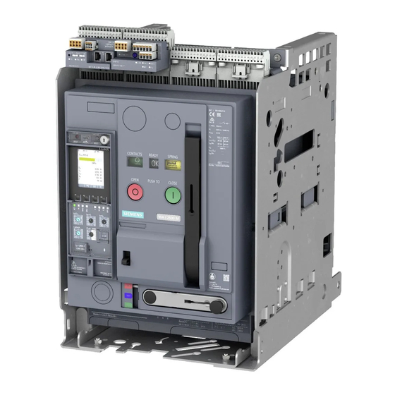
System description The 3WA air circuit breaker The 3WA circuit breaker is the new generation of air circuit breakers in the Siemens AG portfolio. It is based on the proven and robust design of its predecessor 3WL. The technical data of the 3WA circuit breaker mechanics and the portfolio have been extended as compared with 3WL, and the electronic components have been completely redeveloped. - Page 14 System description 2.2 The CubicleBUS² bus system You can find a detailed description of the components including the technical specifications in the 3WA Equipment Manual; see Chapter Reference documents (Page 5). Data exchange between CubicleBUS nodes Data is exchanged internally via CubicleBUS and output at the local interface, I/O modules, or fieldbus interfaces.
-
Page 15: Com190 Communication Module
System description 2.3 COM190 communication module Requirements Communication via the CubicleBus² requires the following hardware components: • 3WA air circuit breaker • ETU600 electronic trip unit • Terminating resistor (120 Ω) • Optional CubicleBUS module Note Compatibility with legacy product The CubicleBUS²... - Page 16 System description 2.3 COM190 communication module • Readout of status and maintenance information • Security functions The COM190 is equipped with Ethernet interfaces for connecting to the PC or network. Communication protocols and systems The COM190 communication module supports the following communication protocols: •...
-
Page 17: Status Of The Circuit Breaker
Status of the circuit breaker Introduction The 3WA air circuit breaker provides a wide range of information about the current status of the circuit breaker and its internal accessories. Both the important status data and the evaluation options in various applications are described below. Display of the ETU600 electronic trip unit Operator panel Rotary switches of the ETU600 electronic trip unit... -
Page 18: The Etu600 Electronic Trip Unit As An Information Center
Status of the circuit breaker 3.2 The ETU600 electronic trip unit as an information center The ETU600 electronic trip unit as an information center The ETU600 electronic trip unit of the 3WA air circuit breaker provides a wide range of information: •... -
Page 19: Indication Of Tripping Cause
Status of the circuit breaker 3.3 Indication of tripping cause Indication of tripping cause The cause of the last tripping operation of the circuit breaker is indicated in the register "Last tripping cause". Name Register (0x0000 HEX) Last tripping cause 0x4EBB Description Comment... -
Page 20: Status Of The Etu
Status of the circuit breaker 3.4 Status of the ETU Number of tripping operations Separate registers exist to indicate the number of individual tripping types. Number of all tripping operations 0x0093 Number of GF tripping operations 0x0095 Number of INST tripping operations 0x0097 Number of LT tripping operations 0x0099... - Page 21 Status of the circuit breaker 3.4 Status of the ETU Description Comment Remote parameterization protection Remote parameterization protection acti- active vated on communication module with role A. Remote parameterization protec- tion is a DIP switch that prevents parame- ters from being changed via communication.
-
Page 22: Status Of The Mechanical System
Status of the circuit breaker 3.5 Status of the mechanical system Status of the mechanical system The register "Status of the circuit breaker mechanical system" is used for monitoring the mechanical system of the circuit breaker. Name Register (0x0000 HEX) Status of mechanical system of circuit breaker 0xCB3B Description... -
Page 23: Status Of Position Of Withdrawable Circuit Breaker In The Guide Frame
Status of the circuit breaker 3.6 Status of position of withdrawable circuit breaker in the guide frame Status of position of withdrawable circuit breaker in the guide frame The register "Circuit breaker position in the guide frame" provides a compact overview of the positions in the guide frame, e.g. -
Page 24: Das+ Status
Status of the circuit breaker 3.7 DAS+ status DAS+ status The DAS+ maintenance mode basically comprises five registers: • DAS+ activation source (0x0FD2) Indicates the source that was used to activate the DAS+ maintenance mode. It is important to know the source, as the DAS+ maintenance mode can only be deactivated again using the source that was used to activate it. - Page 25 Status of the circuit breaker 3.7 DAS+ status Activation source The "DAS+ activation source" register (0x0FD4) shows several activation sources. • The COM A and COM B communication module communications are subdivided internally depending on their protocol. Each protocol is a separate activation source. •...
-
Page 26: Status Of Warnings
Status of the circuit breaker 3.8 Status of warnings Status of warnings Active warnings can be indicated and evaluated in the "ETU warnings" register. Name Register (0x0000 HEX) ETU warnings 0x61DC Description Comment Battery of the ETU600 is dead Refers to the system time. Replace the battery, see Chapter "4.11.4 Replacement battery for the ETU600 electronic trip unit"... -
Page 27: Status Of Alarms
Status of the circuit breaker 3.9 Status of alarms Status of alarms Alarms inform the user that LT or GF protection tripping may occur in the circuit breaker. In these fault current ranges, promptly reducing the fault currents can prevent a protection tripping operation. -
Page 28: Activation Status Of Protective Functions
Status of the circuit breaker 3.10 Activation status of protective functions 3.10 Activation status of protective functions Which protective functions are activated in the circuit breaker can be indicated and evaluated in the register "Activation status of protective functions". Protective functions that require a voltage tap have a second data point. This indicates whether the necessary voltage tap is present. -
Page 29: Status Of The Etu Error Messages (Self-Monitoring Function)
Status of the circuit breaker 3.11 Status of the ETU error messages (self-monitoring function) 3.11 Status of the ETU error messages (self-monitoring function) The ETU600 electronic trip unit has a self-monitoring and diagnostics function. The messages of the watchdogs and diagnostics functions can be indicated and evaluated in the "ETU error messages"... -
Page 30: Status Of The Main Contacts Of The Circuit Breaker
Status of the circuit breaker 3.12 Status of the main contacts of the circuit breaker 3.12 Status of the main contacts of the circuit breaker The status of the main contacts indicates whether checking or replacement of the main contacts is required due to severe contact erosion. The status can be indicated and evaluated in the "Status of the main contacts"... -
Page 31: Parameterization And Remote Control
Parameterization and remote control Parameterization of the protection parameters The main protection parameters can be set on the ETU600 electronic trip unit using rotary switches. Remote parameterization is also possible depending on the position of the rotary switches. The special characteristics and additional register addresses associated with this are described below. - Page 32 Parameterization and remote control 4.1 Parameterization of the protection parameters Setting options for protection parameters of parameter sets A and B Parameter set A (standard) The protection parameters of parameter set A can be set in different ways using the rotary switches: •...
- Page 33 Parameterization and remote control 4.1 Parameterization of the protection parameters Example: Protection parameter ST, setting I Parameter for I Settable via Parameter Register Read / write Setting I Rotary switches 0x1F46 Read-only Source: Rotary switch position or e.SET Setting I for e.SET ETU600 display / com- 0x1F4E...
- Page 34 Parameterization and remote control 4.1 Parameterization of the protection parameters Protection parameter ST setting t Parameters for ST Settable via Parameter set Register Read / write ST tripping time t PS-A Rotary switches 0x1F42 Read-only Source: Rotary switch position or e.SET ST i²t ST characteristic curve ON/OFF PS-A Rotary switches 0x1F44...
-
Page 35: Close/Open Circuit Breaker Via Modbus Tcp
Parameterization and remote control 4.2 Close/open circuit breaker via Modbus TCP Close/open circuit breaker via Modbus TCP Closing or opening of the circuit breaker via the communication connection takes place by means of commands. For information about the commands, see Chapter Writing commands (Page 37). -
Page 36: Parameterization Of Ground-Fault Protection (Gf)
Parameterization and remote control 4.3 Parameterization of ground-fault protection (GF) Parameterization of ground-fault protection (GF) The register addresses for parameterizing the different types of ground-fault protection (GF) are shown below. 3WA Air Circuit Breaker Communication System Manual, 11/2021, 92310000004-02... -
Page 37: Modbus Tcp
Modbus TCP General The COM190 communication module supports the Modbus TCP protocol of the Modbus Organization, described in the following specifications: • Modbus Application Protocol V1.1b3 • Modbus Messaging Implementation Guide V1.0b You can find more information on the Internet (www.modbus.org). Addressing With Modbus TCP, the COM190 module is addressed via its IP address. -
Page 38: Function Codes, Metering Values And Parameters
Modbus TCP 5.3 Function codes, metering values and parameters Function codes, metering values and parameters 5.3.1 Function codes The COM190 communication module supports the following Modbus function codes: • 0x03 – Read values and parameters • 0x06 – Write single register parameters and commands •... -
Page 39: Writing Commands
Modbus TCP 5.3 Function codes, metering values and parameters • If the Modbus TCP whitelist is activated, the Modbus TCP connection must have sufficiently high access rights in order to be able to write the parameter. You can find more information on the Modbus TCP whitelist in Chapter Modbus TCP whitelist (Page 39). -
Page 40: Transactions
Modbus TCP 5.4 Transactions Transactions Every Modbus write frame in the 3WA system (Modbus function code 16 or hex 0x10) constitutes a transaction. A transaction is only executed if all the parameters contained in the frame are accepted by the target components. Note Even if one parameter in the frame is rejected by the target component, all the other parameterizations from this frame are undone. -
Page 41: Invalid Values
Modbus TCP 5.6 Invalid values Invalid values If data points which basically exist but which are not available temporarily are read using Modbus function code 3 (hex: 0x03), the corresponding registers in the Modbus frame of the COM190 are filled with the bit pattern 0xFF (all bits '1') to tag them as invalid. The same fill pattern is used if a data point is only partially read or if reading takes place across a gap that exists between two data points in the Modbus register map. - Page 42 Modbus TCP 5.8 Modbus TCP whitelist IP addresses It is possible to enter up to ten IP addresses or IP address ranges in the COM190. The IP address range is defined by a start IP address and an end IP address. The start IP address and the end IP address and all the IP addresses lying between them are approved.
- Page 43 Modbus TCP 5.8 Modbus TCP whitelist Structure of the whitelist The whitelist contains the following information and entries: • Status - Active Indicates whether or not the whitelist is active. The whitelist is active if at least one filter entry is present and active. The whitelist is deactivated if no filter entry is present or active.
- Page 44 Modbus TCP 5.8 Modbus TCP whitelist Parameterization The Modbus TCP whitelist is deactivated on delivery and can be activated and parameterized using the SENTRON powerconfig configuration software (from version 3.17 or version 2.5 as an app). Parameterization can be performed via the USB or Bluetooth interface of the 3WA circuit breaker or via the Modbus TCP interface of the COM190 communication module.
-
Page 45: Configurable Modbus Tcp Port
Modbus TCP 5.9 Configurable Modbus TCP port Configurable Modbus TCP port It may be necessary to change the number of the TCP port due to applications or to ensure cybersecurity. The TCP port number for Modbus TCP connections can be configured with the SENTRON powerconfig configuration software or as a data point. -
Page 46: Settings
A or the communication module with role B. Note According to the Siemens Cyber Security Disclaimer, the COM190 communication module must not be operated in public networks. The SNTP function of the COM190 is therefore designed for a local NTP time server in closed networks. -
Page 47: Data Points
Modbus TCP 5.10 System time with SNTP 5.10.3 Data points COM190 data points with role A Modbus register number Description Source Format Length (bits) High/Lo 42017 0xA421 – SNTP server address COM190 Unsigned long 42019 0xA423 – SNTP client mode COM190 Unsigned Modbus address = Modbus register –... -
Page 48: Parameters
Modbus TCP 5.10 System time with SNTP 5.10.4 Parameters SNTP mode • SNTP mode Off – The COM190 system time is not synchronized with an NTP time server. • SNTP mode Active: – The SNTP client sends SNTP requests once an hour to synchronize the COM190 system time. -
Page 49: Profinet Io
PROFINET IO General With the COM190 communication module, you can access the data of the 3WA circuit breakers via the PROFINET IO during operation. The PROFINET IO can be operated in parallel with the Modbus TCP protocol (see Chapter Modbus TCP (Page 35)). Overview The COM190 communication module has the following performance features: •... -
Page 50: Technical Specifications Of The Communication Interfaces
PROFINET IO 6.2 Technical specifications of the communication interfaces • IP settings: IP address, subnet, gateway – Using the SENTRON powerconfig configuration software via the USB interface of the 3WA circuit breaker – Via PROFINET DCP protocol (e.g. in the STEP 7 HW Config) •... -
Page 51: Metering Values, Addressing Und Data Traffic
• Stored energy mechanism charged status • Ready-to-close status • Status of the IOM inputs/outputs You can find more information on the metering values under Modbus register for the 3WA air circuit breaker (https://support.industry.siemens.com/cs/ww/en/view/109794278). 3WA Air Circuit Breaker Communication System Manual, 11/2021, 92310000004-02... - Page 52 PROFINET IO 6.3 Metering values, addressing und data traffic Metering values in cyclic and acyclic data traffic The metering values and status information are made available in both cyclic data traffic and acyclic data traffic. • The metering values and status information are made available as follows in cyclic data traffic: –...
-
Page 53: Cyclic Data Traffic
6.3 Metering values, addressing und data traffic After GSDML integration, the 3WA circuit breaker can be found as follows: Hardware catalog → Catalog → Other Field Devices → PROFINET IO → Switching Devices → Siemens AG → Circuit Breaker → SENTRON 6.3.2 Cyclic data traffic In cyclic data traffic, the COM190 communication module exchanges the configured user data with the controller in each set cycle. - Page 54 PROFINET IO 6.3 Metering values, addressing und data traffic Modules that can be plugged in for the project The table below contains the list of all modules that can be plugged in for the project: Module name Length In/Out (bytes) 3WA status and control (fixed in slot 1) In, Out 3WA status (replacement for slot 1)
- Page 55 PROFINET IO 6.3 Metering values, addressing und data traffic Module name Length In/Out (bytes) Apparent power Total Reactive power Total Power factor Total power factor Cos phi Frequency Active energy (double) Import Export Reactive energy (double) Import Export Apparent energy (double) Total Active energy (float) Import...
- Page 56 PROFINET IO 6.3 Metering values, addressing und data traffic Module name Length In/Out (bytes) Status of IO outputs Module 1 Module 2 Module 3 Module 4 Module 5 Selection of the modules The 3WA circuit breaker has a modular design and can be configured individually in the project.
- Page 57 PROFINET IO 6.3 Metering values, addressing und data traffic Binary status information The table below contains a description of the binary status information in the cyclic frame: Byte Value 3WA circuit breaker 0 / 1 0 … 3 Position of the circuit breaker in the guide frame Disconnected position Connected position Test position...
- Page 58 PROFINET IO 6.3 Metering values, addressing und data traffic Control bytes The control bytes for controlling the circuit breaker are always two bytes long. With these control bytes, you can: • Open/close the circuit breaker • Acknowledge tripping events Setting the outputs is edge-triggered. It suffices to set the corresponding bits for 0.5 s. After this, these control bits must be reset to avoid subsequently triggering any undesired actions.
- Page 59 PROFINET IO 6.3 Metering values, addressing und data traffic Free selection of modules The cyclic data can be configured in any way from the available modules. You can find more information in the table provided in the section "Modules that can be plugged in for the project"...
- Page 60 PROFINET IO 6.3 Metering values, addressing und data traffic Basic type 3 Basic type 3 was implemented according to the LVSG profile of the PROFINET user organization (PNO) and comprises fourteen data blocks containing metering values. These are preassigned such that unmodified use is only meaningful with a 3WA circuit breaker with metering function.
- Page 61 PROFINET IO 6.3 Metering values, addressing und data traffic Basic type 5 Basic type 5 comprises six data blocks which are preassigned for a 3WA circuit breaker with metering function. Here only the average voltage values are transmitted. The predefined data blocks cannot be modified. Byte Definition Default...
- Page 62 PROFINET IO 6.3 Metering values, addressing und data traffic Energy data profile e0 Currents Energy data profile e0 is for integration of the 3WA circuit breaker in the Energy Suite profile. The predefined data blocks cannot be modified. Byte Definition Default 0...3 Data block 1...
- Page 63 PROFINET IO 6.3 Metering values, addressing und data traffic Energy data profile e3 Energy Enhanced Energy data profile e3 is for integration of the 3WA circuit breaker in the Energy Suite profile. The predefined data blocks cannot be modified. Byte Definition Default 0..3...
-
Page 64: Acyclic Data Traffic
Definition of data sets You can find a description of the data sets under Modbus register for the 3WA air circuit breaker (https://support.industry.siemens.com/cs/ww/en/view/109794278). In addition to the existing data sets, the I&M0 to I&M4 data sets for identification and maintenance of the circuit breakers/modules according to the PROFINET standard were implemented. - Page 65 Unsigned short 0x0201 IM0 version of the I&M data Unsigned short 0x001E IM0-supported I&M data Total bytes: 60 Default: 42 ("42" stands for Siemens AG) Structure of data set 0xAFF1 (IM1 data: read and write access) Byte Number Format Default Description...
- Page 66 PROFINET IO 6.3 Metering values, addressing und data traffic Structure of data set 0xAFF2 (IM2 data: read and write access) Byte Number Format Default Description of bits Unsigned short 0x0022 Block type: IM2 Unsigned short 0x0038 Block length Unsigned char 0x01 Block version High Unsigned char...
- Page 67 PROFINET IO 6.3 Metering values, addressing und data traffic Error frames data set If a data set is rejected by the COM190, the following happens: • The request is negatively acknowledged with an NRS frame. • The request is signaled to the master with an error frame that includes the negative acknowledgment and error code.
-
Page 68: Interrupt, Error And System Messages
PROFINET IO 6.4 Interrupt, error and system messages Interrupt, error and system messages 6.4.1 General The COM190 communication module is designed as a diagnostics-capable IO device. It detects internal and external faults and signals them to the IO controller as diagnostic, maintenance or process alarms. - Page 69 PROFINET IO 6.4 Interrupt, error and system messages "BlockType" data block 0x0002: AlarmNotification "Low" for diagnostic alarms 0x0001: AlarmNotification "High" for process alarms "BlockLength" data block The number of subsequent bytes of the diagnostic data set is coded in the "BlockLength" data field.
- Page 70 PROFINET IO 6.4 Interrupt, error and system messages Block type for maintenance information The COM190 uses the "Maintenance information" block type to signal that maintenance information is pending. The "UserStructureIdentifier" for the maintenance information block is 0x8100. Structure of the maintenance information Meaning Length UserStructureIdentifier...
- Page 71 PROFINET IO 6.4 Interrupt, error and system messages Block type for diagnostic and maintenance alarm The COM190 uses the "Diagnostic and maintenance" block type to signal incoming and outgoing diagnostic and maintenance alarms as an "Extended channel diagnosis". The "UserStructureIdentifier" for this block type is always 0x8002 for this reason. Structure of the diagnostic and maintenance alarm Interrupt Length...
- Page 72 PROFINET IO 6.4 Interrupt, error and system messages Combination of "ChannelProperties.Qualifier (Bit 9 / 10)" and "ChannelProperties.Specifier (Bit 11 / 12)" Mainte- Mainte- Specifi- Meaning Diagnosis in the nance Re- nance De- er bit SIMATIC S7 300 and quired Bit 9 manded 12 / 11 SIMATIC S7 400 user pro-...
- Page 73 PROFINET IO 6.4 Interrupt, error and system messages "ChannelProperties.Direction (Bits 13 to 15)" data block Value Meaning Manufacturer-specific Input Output Input/Output 100 … 111 Reserved "ChannelErrorType" data block The messages for the diagnostic and maintenance alarms are transferred in the "ChannelErrorType"...
-
Page 74: Diagnostic And Maintenance Alarm Messages
PROFINET IO 6.4 Interrupt, error and system messages 6.4.3 Diagnostic and maintenance alarm messages The more precise alarm information is defined as follows in the "ChannelErrorType" and "ExtChannelErrorType" fields specifically for the COM190: ChannelErrorType (hex) / message ExtChannelErrorType 0x0100 (Diag) - Reserved - Circuit breaker has tripped. - Page 75 PROFINET IO 6.4 Interrupt, error and system messages Block type for process alarm The COM190 uses the "Process alarm" block type to signal process alarms. The "UserStructureIdentifier" for this block type is defined as "User specified" and can be in the range 0x0001 to 0x7FFF.
-
Page 76: Process Alarm Messages
CubicleBUS² module status has Length: 8 bytes changed. Refer to the description of the "ACTIVE_MODULES" data point under Modbus register for the 3WA air circuit break- (https://support.industry.siemens.com/cs/ww/en/view/109 794278). 0x0002 Length: 1 byte Status of the main contacts 0x01 = Main contacts open of the circuit breaker has changed. -
Page 77: Disposal
Disposal Disposal of waste electronic equipment Waste electronic equipment must not be disposed of as unsorted municipal waste, e.g. household waste. When disposing of waste electronic equipment, the current local national/international regulations must be observed. Disposal of batteries Batteries must not be disposed of as unsorted municipal waste, e.g. household waste. When disposing of batteries, the current local national/international regulations must be observed. - Page 78 Disposal 3WA Air Circuit Breaker Communication System Manual, 11/2021, 92310000004-02...
-
Page 79: Esd Guidelines
ESD guidelines Electrostatic sensitive devices (ESD) ESD components are destroyed by voltage and energy far below the limits of human perception. Voltages of this kind occur as soon as a device or an assembly is touched by a person who is not electrostatically discharged. ESD components which have been subject to such voltage are usually not recognized immediately as being defective, because the malfunction does not occur until after a longer period of operation. - Page 80 ESD guidelines A.1 Electrostatic sensitive devices (ESD) ESD seat ESD standing position ESD seat and ESD standing position Protective measures Conductive floor ESD table ESD footwear ESD smock ESD bracelet Cubicle ground connection 3WA Air Circuit Breaker Communication System Manual, 11/2021, 92310000004-02...
-
Page 81: List Of Abbreviations
List of abbreviations Table of abbreviations Abbreviation Meaning Alarm Breaker status sensor Communication module Canadian Standards Association DAS+ Dynamic Arc-Flash Sentry Deutsches Institut für Normung e. V. (German Institute for Standardization) Electrostatic sensitive device European Standard Electrostatic sensitive device Electronic Trip Unit G alarm Ground-fault alarm G tripping...