Dometic 9100 Installation Manual
Power patio awning hardware
Hide thumbs
Also See for 9100:
- User manual ,
- Installaiton instructions (14 pages) ,
- Operation instructions manual (11 pages)
Table of Contents
Advertisement
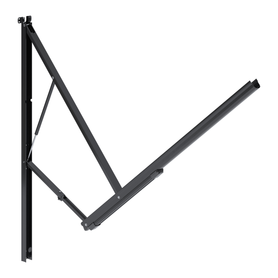
AWNINGS
POWER PATIO AWNING HARDWARE
Hardware
8952XX1.4X0#(L) Basement
8952XX2.4X0#(L) Standard
8952XX3.4X0#(L) Reduced Pitch
FRTA
Fabric Roller Tube Assembly
91XXXYY.XXX#(L)
9100 Power Patio Awning
EN
Installation Manual . . . . . . . . . . . . . . . . . . . . .2
WARNING
REVISION K Form No. 3312737.054 2022-09-30 | ©2022 Dometic Corporation
Cancer and Reproductive Harm
www.P65Warnings.ca.gov
RÉVISION K Document no 3312738.052 2022-09-30 | ©2022 Dometic Corporation
Advertisement
Table of Contents

Related Manuals for Dometic 9100


Summary of Contents for Dometic 9100
- Page 1 9100 Power Patio Awning Installation Manual .....2 WARNING REVISION K Form No. 3312737.054 2022-09-30 | ©2022 Dometic Corporation Cancer and Reproductive Harm www.P65Warnings.ca.gov...
-
Page 2: Table Of Contents
Find the installation manual in French online at documentation, may be subject to changes and updates. For up-to- https://documents.dometic.com/ date product information, please visit www.dometic.com. ?object_id=56434 Contents Explanation of Symbols and Safety Instructions ......2 1 Explanation of Symbols and Recognize Safety Information . -
Page 3: Supplemental Directives
• Use for purposes other than those described in this ANSI/NFPA1192, Recreational Vehicles Code manual Canada Dometic reserves the right to change product appearance and product specifications. CSA C22.1, Parts l & ll, Canadian Electrical Code CSA Z240 RV Series, Recreational Vehicles 3 General Information 1.4 General Safety Messages... -
Page 4: Tools And Materials
Specifications 9100 Power Patio Awning 3.1 Tools and Materials Dometic recommends that the following tools and materials be used while installing the appliance. Included Parts Quantity 1/4-20 x 3/4 in. Hex Head Screw 1/4 in. Split Lock Washer #14-10 x 1-1/2 in. Hex Head Screw #6-20 x 7/16 in. -
Page 5: Door Clearance
9100 Power Patio Awning Preinstallation 4.2 Door Clearance 5 Preinstallation Consider the location of doors, windows, lights, trim, NOTICE: Do not allow the corner of the entry door to slideouts, etc. when determining the length and position contact the awning fabric. Otherwise, premature wear of the awning so as not to obstruct the operation or or tearing of the awning fabric could occur. -
Page 6: Preparing The Awning Rail
Preinstallation 9100 Power Patio Awning 5.2.1 Preparing the Awning Hardware WARNING: IMPACT, PINCH, AND/OR CRUSH HAZARD. Failure to obey the following warnings could result in death or serious injury: • Do not remove the ties wrapped around each arm assembly until the top casting is secured to the front channel, the awning fabric is attached to the awning rail, and the arm assembly is mounted to the RV. -
Page 7: Determining The Awning Location
9100 Power Patio Awning Preinstallation The groove in the top casting must slide over the tongue in the main arm. 7 Correctly Positioned Tongue in Groove 9 Securing the Left-Hand Front Channel Groove Tongue Top Casting Cotter Pin 2. Position the right-hand top casting in the main arm... -
Page 8: Installation
Installation 9100 Power Patio Awning 6.1.1 Installing a Wired Awning Switch Consider the following when selecting the mounting awning mounting location: 1. Shut off the gas supply, disconnect the 120 VAC • Select a solid structure in the RV wall for the support power from the RV, and disconnect the positive (+) of the top mounting brackets and back channels. -
Page 9: Installing The Awning
9100 Power Patio Awning Installation 2. Choose an installation location for the LED light collapse. Failure to obey this warning could result in switch where it will not be exposed to weather, death or serious injury. extreme temperatures, or long hours in direct CAUTION: LIFTING HAZARD. - Page 10 Installation 9100 Power Patio Awning At least two other people are required to hold Some awning rails have a wide drip channel and control the awning hardware until the to catch water as it runs off the RV roof. If the...
-
Page 11: Attaching The Back Channels
9100 Power Patio Awning Installation 6.3 Attaching the Back Channels 7. With the arm assembly completely closed, place the top mounting brackets against the wall and align the mounting holes to the pre-drilled holes in the RV. 8. Apply sealant to the screw threads. - Page 12 Installation 9100 Power Patio Awning 15 Accessing the Marked Hole Locations 16 Securing the Back Channel Marked Hole Right-Hand Arm Bottom Wiring 3/16 x 1 in. Oscar Locations Assembly Harness Hole Rivet Back Channel 5. Carefully swing the right-hand arm assembly out of the way to expose the marked hole locations.
-
Page 13: Wiring The Electrical Connections To The Awning
LED light strip (RED or WHITE wire positive, BLACK wire negative). See “6.1.3 Installing a LED Light Switch” on page 8. 5. Follow the instructions included with the Dometic LED light switch kit to complete the installation. 6. Secure the wiring to prevent pinching or other damage during awning operation. -
Page 14: Installing The Bumper Kit
Installation 9100 Power Patio Awning 6.6 Installing the Bumper Kit 1. Connect the positive (+) 12 VDC terminal from the supply battery. Awnings longer than 21 ft require the installation 2. Fully retract the awning to verify that the hardware is of a bumper kit. -
Page 15: Disposal
9100 Power Patio Awning Disposal LIMITED ONE-YEAR 3. If there is misalignment, adjust the arm assembly: WARRANTY a. Loosen the back channel and top mounting bracket screws. b. Align the back channel. LIMITED ONE-YEAR WARRANTY AVAILABLE AT DOMETIC.COM/EN-US/TERMS-AND-CONDITIONS- c. Re-tighten the screws. - Page 16 YOUR LOCAL YOUR LOCAL YOUR LOCAL DEALER SUPPORT SALES OFFICE dometic.com/dealer dometic.com/contact dometic.com/sales-offices...