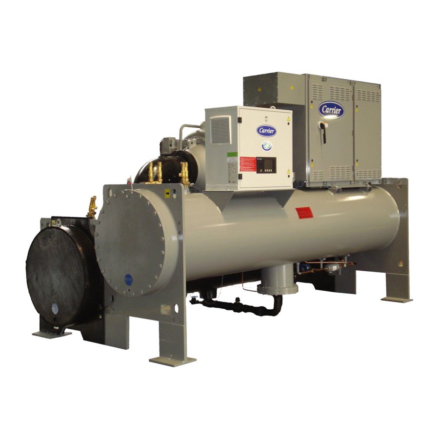
Carrier 19XRV Start-Up And Service Instructions
With pic 6 controls danfoss vlt fc102
Hide thumbs
Also See for 19XRV:
- Operation, maintenance and installation manual (200 pages) ,
- Start-up, operation and maintenance instructions manual (160 pages) ,
- Installation instructions manual (76 pages)
Table of Contents
Advertisement
Quick Links
Start-Up and Service Instructions
CONTENTS
SAFETY CONSIDERATIONS . . . . . . . . . . . . . . . . . . . . 1
INTRODUCTION . . . . . . . . . . . . . . . . . . . . . . . . . . . . . . 3
ABBREVIATIONS AND EXPLANATIONS . . . . . . . . . . 3
Required Publications . . . . . . . . . . . . . . . . . . . . . . . . . 3
Getting Assistance from Danfoss . . . . . . . . . . . . . . . 3
IDENTIFYING DRIVE COMPONENTS . . . . . . . . . . . . . 4
Rigging . . . . . . . . . . . . . . . . . . . . . . . . . . . . . . . . . . . . . 7
Components and Physical Data . . . . . . . . . . . . . . . . . 9
D Size Drive . . . . . . . . . . . . . . . . . . . . . . . . . . . . . . . . 10
E Size Drive. . . . . . . . . . . . . . . . . . . . . . . . . . . . . . . . . 12
D and E Size VFD Power Panel Schematics . . . . . . 15
PD Size Drive . . . . . . . . . . . . . . . . . . . . . . . . . . . . . . . 17
Control Shelf. . . . . . . . . . . . . . . . . . . . . . . . . . . . . . . . 19
PD Module. . . . . . . . . . . . . . . . . . . . . . . . . . . . . . . . . . 20
DC Bus . . . . . . . . . . . . . . . . . . . . . . . . . . . . . . . . . . . . 21
START-UP . . . . . . . . . . . . . . . . . . . . . . . . . . . . . . . . . . 23
Alternate Wire Lugs . . . . . . . . . . . . . . . . . . . . . . . . . . 23
Verify Installation . . . . . . . . . . . . . . . . . . . . . . . . . . . . 23
Configure the VFD . . . . . . . . . . . . . . . . . . . . . . . . . . . 24
Commissioning the Unit . . . . . . . . . . . . . . . . . . . . . . 24
SERVICE . . . . . . . . . . . . . . . . . . . . . . . . . . . . . . . . . . . 24
Troubleshooting the Drive . . . . . . . . . . . . . . . . . . . . 25
Power Off - Static Test . . . . . . . . . . . . . . . . . . . . 30
Servicing the Drive. . . . . . . . . . . . . . . . . . . . . . . . . . . 30
SAFETY CONSIDERATIONS
Centrifugal and screw compressor liquid chillers are designed to
provide safe and reliable service when operated within design
specifications. When operating this equipment, use good judg-
ment and safety precautions to avoid damage to equipment and
property or injury to personnel.
Be sure you understand and follow the procedures and safety pre-
cautions contained in the chiller instructions as well as those listed
in this guide.
Manufacturer reserves the right to discontinue, or change at any time, specifications or designs without notice and without incurring obligations.
Catalog No. 04-53190077-01
Page
Printed in U.S.A.
Form 19XR-CLT-19SS
Danfoss VLT FC102
DANGER
Failure to follow these procedures will result in severe personal
injury or death.
ONLY QUALIFIED electrical personnel familiar with the
construction and operation of this equipment and the hazards
involved should install, adjust, operate, or service this
equipment.
READ AND UNDERSTAND this manual and other applica-
ble manuals in their entirety before proceeding. Failure to ob-
serve this precaution could result in severe bodily injury or loss
of life.
DO NOT install modification kits with power applied to the
drive. Disconnect and lock out incoming power before at-
tempting such installation or removal. Failure to observe this
precaution could result in severe bodily injury or loss of life.
UNUSED WIRES in conduit must be grounded at both ends to
avoid a possible shock hazard caused by induced voltages. Al-
so, if a drive sharing a conduit is being serviced or installed, all
drives using this conduit should be disabled to eliminate the
possible shock hazard from cross-coupled motor leads. Failure
to observe these precautions could result in bodily injury.
DO NOT VENT refrigerant relief valves within a building.
Outlet from rupture disc, relief valve or any other type of safety
relief device must be vented outdoors in accordance with the
latest edition of ANSI/ASHRAE 15 (American National Stan-
dards Institute/American Society of Heating, Refrigerating,
and Air-Conditioning Engineers). The accumulation of refrig-
erant in an enclosed space can displace oxygen and cause as-
phyxiation.
PROVIDE adequate ventilation in accordance with ANSI/
ASHRAE 15, especially for enclosed and low overhead spac-
es. Inhalation of high concentrations of vapor is harmful and
may cause heart irregularities, unconsciousness, or death. Mis-
use can be fatal. Vapor is heavier than air and reduces the
amount of oxygen available for breathing. Product causes eye
and skin irritation. Decomposition products are hazardous.
DO NOT USE OXYGEN to purge lines or to pressurize a
chiller for any purpose. Oxygen gas reacts violently with oil,
grease, and other common substances.
NEVER EXCEED specified test pressures. VERIFY the al-
lowable test pressure by checking the instruction literature and
the design pressures on the equipment nameplate.
DO NOT USE air for leak testing. Use only refrigerant or dry
nitrogen.
DO NOT VALVE OFF any safety device.
BE SURE that all pressure relief devices are properly installed
and functioning before operating any chiller.
THERE IS A RISK OF INJURY OR DEATH by electrocu-
tion. High voltage may be present on the motor leads even
though the motor is not running. Open the power supply dis-
connect before touching motor leads or terminals.
(Dangers continued on next page.)
Pg 1
19XRV
with PIC 6 Controls
12-21
Replaces: NEW
Advertisement
Table of Contents

Related Manuals for Carrier 19XRV


Summary of Contents for Carrier 19XRV
-
Page 1: Table Of Contents
19XRV with PIC 6 Controls Danfoss VLT FC102 Start-Up and Service Instructions CONTENTS DANGER Page Failure to follow these procedures will result in severe personal SAFETY CONSIDERATIONS ....1 injury or death. - Page 2 DANGER CAUTION Failure to follow these procedures may result in personal inju- Failure to follow these procedures may result in personal inju- ry or death. ry or damage to equipment. DO NOT work on high-voltage equipment unless you are a TO AVOID an electric shock hazard, verify that the voltage on qualified electrician.
-
Page 3: Introduction
INTRODUCTION The Carrier VFD option Start-Up and Service Manual is intended Carrier P/N: for trained and qualified service personnel and is to be used during start-up, operation, and maintenance of Danfoss VLT FC102 SEE NOTE: 1 series drives. T/C: FC-102N560T4E54H2TXC7CXS009XAXBXCXXXXDX... -
Page 4: Identifying Drive Components
Instructions. Note that a keypad is required for some service functions such as enabling LEN on a non-Carrier configured Dan- foss type code. (LEN is configured default on a Carrier type code.) WARNING A keypad is also required if a drive power card is being replaced. - Page 5 PIC6 HMI DISCONNECT HANDLE METER OPTION (OPTIONAL) E-STOP D-SIZE DANFOSS AIR-COOLED DRIVE Fig. 3 — D Size Drive INCOMING NOTE: INSTALL CARRIER-PROVIDED TOPHAT TO ALLOW FOR ADEQUATE SPACE FOR POWER INCOMING POWER CABLES. ACCESS METER OPTION (OPTIONAL) POWER PANEL CONDUIT CONTAINING...
- Page 6 NOTE: INSTALL CARRIER-PROVIDED TOPHAT TO ALLOW FOR ADEQUATE SPACE FOR INCOMING POWER CABLES. INCOMING POWER CABLES MAIN CIRCUIT BREAKER HANDLE E-STOP PD DRIVE Fig. 5 — Size PD Danfoss Drive (Integrated VFD and VFD Power Panel) Table 2 — VFD Type by Frame Size, D-E...
-
Page 7: Rigging
Rigging D, E SIZES Drive enclosure and associated components are heavy. To avoid injury be sure to use appropriate equipment with appropriate weight ratings for lifting. Always use dedicated lifting eyes for lifting and never walk under suspended load. Wear PPE such as gloves, safety glasses and safety shoes to prevent injury. -
Page 8: Parallel Drive Modules
PARALLEL DRIVE MODULES Parallel Drive Modules consist of four smaller D size modules installed in parallel configuration. Install eye bolts and rig individual modules as a D series drive. Note that some component removal is necessary to gain access to remove an individual drive. -
Page 9: Components And Physical Data
Compressor Frame 3, 4, 5 — Single-Stage — 440-480/60 C, E — Two-Stage Heat Exchanger Size Fig. 10 — Carrier Part Number for 19XRV Danfoss Drive AX BX CX X XX DX FC-102 N560 T4 E54 S009 Product Group FC-102 D Options DX —... -
Page 10: D Size Drive
Fig. 12 — D Size FC-102 Drive and Carrier VFD Power Panel INCOMING POWER OPTION: METER KIT (AMMETER AND VOLTMETER) DISPLAY AND SWITCHES MAIN CIRCUIT BREAKER DISCONNECT HANDLE Fig. 13 — Carrier VFD Power Panel for D and E Size Drives (D size panel shown) - Page 11 LCP (Local Control Panel) — not provided RS-485 Serial Bus Connector Digital I/O and 24V Power Supply Analog I/O Connector USB Connector Serial Bus Terminal Switch Analog Switches (A53), (A54) Relay (01, 02, 03) Relay 2 (04, 05, 06) Lifting Ring Mounting Slot Cable Clamp (PE) Ground...
-
Page 12: E Size Drive
For the smaller D size drives, customer incoming power is termi- E Size Drive nated in the VFD Power Panel; power leads are run from the The E size FC102 drives have higher amperage capacity com- VFD Power Panel to the VFD and from the VFD to the motor pared to the D size. - Page 13 CIRCUIT BREAKER 1 (OIL PUMP SUPPLY) MAIN FUSE 4; 2 AMP FUSE CIRCUIT FUSE 3; 25 AMP FUSE BREAKER CIRCUIT BREAKER 2 (OIL HEATER SUPPLY) TERMINAL BLOCK (TB8) TERMINAL BLOCK (TB5) ANALOG CONTROL RELAY (ACR) OPTION: SURGE PROTECTIVE DEVICE OPTION: METER KIT TERMINAL BLOCKS AND FUSE 9-14 SERVICE CIRCUIT...
- Page 14 61 68 39 42 50 Remove Jumper to activate Safe Stop 29 32 RELAY 1 RELAY 2 LCP Cradle (LCP not shown or provided) Bus Terminal Switch Serial Communication Terminals Digital Input/Output Terminals Cable/EMC Clamps Relay 1 and Relay 2 Control Card (underneath LCP and Control Terminals) + REGEN 82 - REGEN 83...
-
Page 15: D And E Size Vfd Power Panel Schematics
D and E Size VFD Power Panel Schematics See Fig. 22 and 23 for detailed drawings. LEGEND — Analog Control Relay — Alarm ALMR — Alarm Relay — Auxiliary COMP — Compressor Motor — Control Relay — Control Transformer — Door Switch —... - Page 16 Fig. 23 — Danfoss D and E Size VFD Power Panel Schematic (Ammeter, Voltmeter, and Surge Protective Device Options)
-
Page 17: Pd Size Drive
D and E drive size offering. See Fig. 24-26. Parallel drive (PD) systems consist of four D size FC-102 drives NOTE: Enclosure does not represent Carrier application. mounted in a common enclosure, creating a larger PD size with greater ampacity than D and E size drives. - Page 18 FU8, FU10, FU11 (OPTION) (OPTION) (OPTION) ACR RELAY FU1, FU2, FU3 CR1 RELAY TB4, TB5, TB8 Fig. 26 — Control Section Component Identification...
-
Page 19: Control Shelf
Control Shelf The control shelf contains the MDCIC (multi-drive control inter- face card), and control card. The MDCIC is connected to each of the drive modules via a ribbon cable and communicates to the control card. The control card controls the operation of the drive modules. -
Page 20: Pd Module
PD Module Each drive module has an IP00 protection rating. Four modules are connected in parallel to create a drive system. See Fig. 28-29. DC-link terminal and DE fuse MDCIC plug Microswitch to DC fuse connector Relay 1 and 2 connector Brake fault jumper and connector Mains input terminals (inside the unit) Terminal cover... -
Page 21: Dc Bus
DC Bus When testing parallel drive systems do the following: • To access the DC bus voltage, use the REGEN terminals at the top of one of the modules. • When testing DC bus voltage for the entire system, it is not necessary to remove the interlink connections between the individual drives. - Page 22 Fig. 31 — Danfoss PD VFD Module Wiring Schematic...
-
Page 23: Start-Up
START-UP Alternate Wire Lugs If the incoming power wire size in the VFD power panel does DANGER not fit the standard lug, alternate lugs may be available. Please contact the circuit breaker manufacturer for availability. Note Internal components and circuit boards of the drive are live that lugs rated for a higher current than the circuit breaker may when the drive is connected to incoming power. -
Page 24: Configure The Vfd
Commissioning the Unit The commission procedure is as follows: 1. If the chiller has been stored outdoors, allow at least 24 hours room temperature stabilization prior to commis- sioning. Ensure any condensation that occurs as a result of the ambient temperature is allowed to evaporate. 2. -
Page 25: Troubleshooting The Drive
Programming; Make sure that drive parameter settings are done with Danfoss MCT-10 software or a customer-supplied correct according to motor, application, I/O configuration. LCP (Local Control Panel). See the 19XRV Controls Operation • Proper clearance; Drives require adequate top and bottom and Troubleshooting manual for PIC6 controls for chiller Alarm clearance to ensure proper airflow for cooling. - Page 26 Table 6 — Typical Fault Code Descriptions and Corrective Actions* PIC6 DISPLAY DANFOSS ALARM/ DESCRIPTION AND DANFOSS ALARM PIC6 ALARM CODE PIC 6 - DESCRIPTION DANFOSS VFD ALARM WARNING CODE POSSIBLE CORRECTIVE ACTION IN MAINTENANCE MENU This warning or alarm only appears if programmed in Live zero error VFD Fault Live Zero Error...
- Page 27 Default setting in 14-53 is [1]=Warning. Brake resistor short VFD Fault Brake Res Short Cir Not relevant; Carrier has no brake resistor. circuit Brake resistor VFD Fault Brake OverLoad Not relevant; Carrier has no brake resistor.
- Page 28 If an option card is present, check for overvoltage. AMA internal fault VFD Fault AMA Not OK Not relevant; Carrier default has AMA =0 [off]. Current is higher than the value in P4-18 Current Current Limit VFD Fault Limit. Verify configured motor data.
- Page 29 LEN Communication error with VFD is lost. Check wiring. Note that for new drive not factory configured for Carrier or after software upgrade LEN must be enabled. Set parameter 14-29 to 00006100. This gives access to hidden parameter 14-23. Change...
-
Page 30: Checking Power Modules And Motor Input With Input
test is too low to accurately test a diode. Make sure the meter is set Checking Power Modules and Motor Input with to the diode test function. Voltage readings may not be exact as Input Power Off — Static Test shown in above table, but look for consistency during each of the Use the following procedure to check the drive’s power module 4 tests. - Page 31 APPENDIX A — WIRING SCHEMATICS 19XRV CHILLER CONTROL SCHEMATIC (PIC 6)
- Page 32 APPENDIX A — WIRING SCHEMATICS (CONT) 19XRV CHILLER CONTROL SCHEMATIC (PIC 6) (cont)
- Page 33 APPENDIX A — WIRING SCHEMATICS (CONT) 19XRV COMPRESSOR POWER PANEL SCHEMATIC...
- Page 36 © 2021 Carrier Manufacturer reserves the right to discontinue, or change at any time, specifications or designs without notice and without incurring obligations. Catalog No. 04-53190077-01 Printed in U.S.A. Form 19XR-CLT-19SS Pg 36 12-21 Replaces: NEW...