Table of Contents
Advertisement
Quick Links
Advertisement
Table of Contents

Summary of Contents for Agilent Technologies E3620A
- Page 1 Manual Part No. E3620-90001...
-
Page 2: Safety Summary
SAFETY SUMMARY... -
Page 4: General Information
GENERAL INFORMATION... -
Page 5: Installation
Table 1. Specifications INSTALLATION... -
Page 6: Input Power Requirements
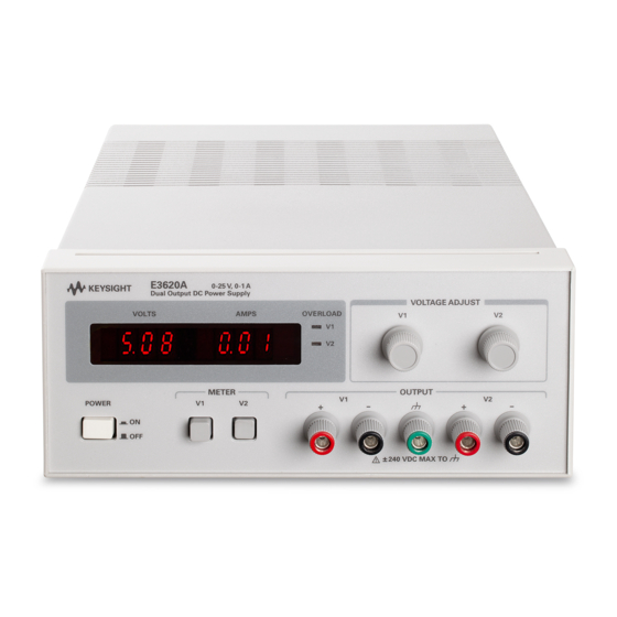
) set the voltage This section describes the operating controls and indicators, level of the corresponding output. The voltage controls are 10 turn-on checkout procedures, and other operating consider- turn potentiometers. ations for the Model E3620A Dual Output Power Supply. -
Page 7: Turn-On Checkout Procedure
OPERATION internally across each output protect the supply's output filter The dual outputs of the E3620A can be used individually, in capacitors against reverse voltages. This could occur if the sup- series, or in parallel. Each output can be floated (up to 240 plies are connected in series and the output is shorted. -
Page 8: Reverse Current Loading
peak currents (as occur in pulse loading) may exceed the OUTPUT CAPACITANCE preset current limit and cause crossover to occur and An internal capacitor across the output terminals of the supply degrade performance. helps to supply high-current pulses of short duration during constant-voltage operation. -
Page 9: Service Information
SERVICE INFORMATION (Block Diagram Overview) -
Page 10: Maintenance
The input ac line voltage is first applied to the preregulator which operates in conjunction with the preregulator control circuit to rectify the tap switched AC voltage. This preregu- lator minimizes the power dissipated in the series regulating elements by controlling the dc level across the input filter capacitors depending on the output voltage. -
Page 11: Performance Tests
Table A-1. Test Equipment Required TYPE REQUIRED CHARACTERISTICS RECOMMENDED MODEL Oscilloscope Display transient response and ripple Agilent 54503A Sensitivity : 100BµV and noise waveforms. Bandwidth : 20 MHz/100 MHz RMS Voltmeter True rms, 20 MHz bandwidth Measure rms ripple and noise Sensitivity : 1 mV voltage. - Page 12 and that the current limit circuits function, proceed as follows: Rated Output Voltage and Voltmeter Accuracy a. With no loads connected: turn on the supply and push the V1 METER switch in. Connect a DVM between the V1 + and - terminals and set V1 VOLTAGE control until front panel voltmeter indicates 17.00 volts.
- Page 13 Load Regulation (Load Effect) RMS Measurement Definition: The change, , in the static value of dc out- The rms measurement is not an ideal representation of the put voltage resulting from a change in load resistance from noise, since fairly high output noise spikes of short duration open circuit to the value that yields maximum rated output could be present in the ripple and not appreciably increase current (or vice versa).
- Page 14 c. Connect the DVM across R . Operate the DVM in ac volt- Adjust the oscilloscope to display transients as shown in Figure A-9. age mode. g. Check that the pulse width (t ) of the transients at 15 d. Turn on the supply. mV from the base line is no more than 50 µsec as shown.
-
Page 15: Troubleshooting
TROUBLESHOOTING c. If none of the symptoms of Table A-2 apply, proceed to Table A-3. This table provides an initial troubleshooting Before attempting to troubleshoot the power supply, ensure procedure that also directs you to the more detailed pro- that the fault is with the supply and not with an associated cedures which follow it. - Page 16 Table A-4. Output Voltage Bias and Reference Voltage Check STEP ACTION RESPONSE NEXT ACTION Check +12V bias. a. Normal (+12V ± 5%) a. Proceed to step (3). b. Voltage high b. Check U13(for V2 output) or U23(for V1 output) for short.
- Page 17 Table A-6. VT Supply Troubleshooting SYMPTOM STEP - ACTION RESPONSE PROBABLE CAUSE High output voltage 1. Attempt to turn off Q1 by a. Output voltage remains high. a. Q1 shorted. (higher than rating) shorting emitter-to-col- b. Output voltage decreases. b. Remove short and proceed to step lector of Q6.
- Page 18 Table A-8. V2 Preregulator/Control Circuit Troubleshooting (Cont’d) Measure the voltage for pin 14 of U6. a. Low voltage(-12 V). a. U4 defective. b. High voltage(+12 V). b. Proceed to step 7. Measure the voltage for pin 14 of U7. a. High voltage(+12 V). a.
- Page 20 Table A-11. Replaceable Parts List REFERENCE Agilent PART Q'TY DESCRIPTION MFR. MFR. P/N DESIGNATE NUMBER CODE A-12...
- Page 21 Table A-11. Replaceable Parts List(cont'd) REFERENCE Agilent PART Q'TY DESCRIPTION MFR. MFR. P/N DESIGNATE NUMBER CODE A-13...
- Page 22 Table A-11. Replaceable Parts List(cont'd) REFERENCE Agilent PART Q'TY DESCRIPTION MFR. MFR. P/N DESIGNATE NUMBER CODE MISCELLANEOUS A-14...
-
Page 26: Declaration Of Conformity
DECLARATION OF CONFORMITY...


