Graco LDP5 Instructions Manual
Preset electronic metered dispense valves
Hide thumbs
Also See for LDP5:
- Instructions manual (33 pages) ,
- Parts and accessories installation instructions (2 pages) ,
- Instructions manual (31 pages)
Table of Contents
Advertisement
Quick Links
Instructions
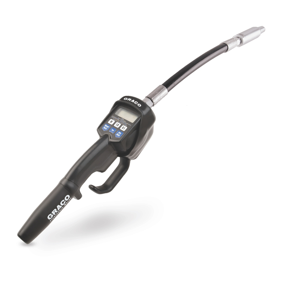
LDP5 (Preset) Electronic
Metered Dispense Valves
For metered dispense of oils and antifreeze only. Do not dispense windshield washer
solvent. For professional use only.
Not approved for use in European explosive atmosphere locations.
Model
1000 psi (6.9 MPa, 69 bar) Maximum Working Pressure
See page 3 for model information.
Important Safety Instructions
Read all warnings and instructions in this
manual before using the equipment.
Save these instructions.
312668ZAC
Model 256216 Shown
EN
Advertisement
Table of Contents

Related Manuals for Graco LDP5


Summary of Contents for Graco LDP5
- Page 1 Instructions LDP5 (Preset) Electronic Metered Dispense Valves 312668ZAC For metered dispense of oils and antifreeze only. Do not dispense windshield washer solvent. For professional use only. Not approved for use in European explosive atmosphere locations. Model 1000 psi (6.9 MPa, 69 bar) Maximum Working Pressure See page 3 for model information.
-
Page 2: Table Of Contents
Pressure Relief Procedure ....10 LDP5 Meter Setup ..... . . 10 Locking and Unlocking the Trigger . -
Page 3: Models
Models Models Extension Inlet Impact Swivel Meter Model No. Guard Cover Rigid Flex BSPT BSPP LDP5 255277 LDP5 256216 LDP5 258694 LDP5 24F883 LDP5 24F884 LDP5 24F886 LDP5 24F889 LDP5 24F890 LDP5 24F892 LDP5 24X465 LDP5 26D917 312668ZAC... -
Page 4: Warnings
Warnings Warnings The following warnings are for the setup, use, grounding, maintenance, and repair of this equipment. The exclamation point symbol alerts you to a general warning and the hazard symbols refer to procedure-specific risks. When these symbols appear in the body of this manual or on warning labels, refer back to these Warnings. Product-specific hazard symbols and warnings not covered in this section may appear throughout the body of this manual where applicable. - Page 5 Warnings WARNING FIRE AND EXPLOSION HAZARD When flammable fluids are present in the work area, such as gasoline and windshield wiper fluid, be aware that flammable fumes can ignite or explode. To help prevent fire and explosion: • Use equipment only in well-ventilated area. •...
-
Page 6: Typical Installation
. 1 is only a guide for NOTICE selecting and installing system components. Contact • Do not use this dispense valve on non-Graco your Graco distributor for assistance in planning a consoles.The trigger could be inadvertently system. pressed while the dispense valve is stowed. -
Page 7: Installation
Installation Installation Installation Procedure This dispense valve must be calibrated after installation (beginning on page 14). Dispense amounts vary with fluid pressure, temperature, and type of fluid NOTICE dispensed. For new installations, or when there is contaminated This dispense valve is designed for indoor use only, for fluid in the lines, flush the lines before installing the use with industrial grade batteries (see page 21), and is meter valve, to avoid valve leakage. -
Page 8: Installation
Installation Connect Hose to Meter 1. Follow the Pressure Relief Procedure, page 10. 2. Slide the swivel cover (34) onto the hose, small end first, before connecting the hose fitting to the swivel (4) (F . 5). 3. Apply thread sealant to the male threads of the hose fitting. - Page 9 4. Open all of the dispense position shut off valves (B) ans start the pump to pressurize the system. See LDP5 Meter Operation, page 16 for proper operation of the meter (F . 7). •...
-
Page 10: Operation
Operation Operation Pressure Relief Procedure LDP5 Meter Setup Follow the Pressure Relief Procedure whenever Locking and Unlocking the Trigger you see this symbol. To lock the trigger (F . 8), press on the part of the trigger that has the textured grip until it clicks into the locked position. -
Page 11: Terms
Operation Terms Keypad Buttons The following terms are shown on the display or used in this instruction manual. • R-TOTAL: Resettable Total Shows the cumulative amount dispensed in all modes. Can be reset to zero. LITERS AUTO R-TOTAL • TOTAL: Non–resettable Total Shows the cumulative amount dispensed in all modes for the life of the unit. -
Page 12: Setup Menus
Operation Setup Menus b. Second screen: Units of Measure Menu (F . 13, page 13) - the last set Unit of Measurement blinks in the lower right corner on the screen. LITERS c. Third screen: Calibration Menu (F . 14, page AUTO R-TOTAL 14) - CAL blinks on the screen. -
Page 13: Units Of Measurement
Operation 3. Do one of the following: 1. If the Units of Measurement Menu is not already displayed, complete steps 1- 3 in Setup Menus, a. Press and hold the Man- page 12. ual / Reset button to reset the total to zero (0). 2. -
Page 14: Calibration
Operation Calibration b. Press and hold the Manual / Reset button Recalibrate the meter for dispensing different fluids. until CAL stops blink- ing. c. When CAL starts to blink again, the display should show 1.00, which indicates the new calibration is com- plete. -
Page 15: Shut Off Default Amount
Operation 2. AUTO blinks indicating the Auto Preset Amount Shut Off Default Amount Menu. The currently stored auto preset amount is Prevents accidental overfills when dispensing with the displayed. (This is the amount displayed when the trigger locked in Manual mode. The shut off default Auto / Reset button is pressed during normal oper- amount is factory preset at 5 quarts. -
Page 16: Ldp5 Meter Operation
Operation LDP5 Meter Operation 3. Do one of the following: a. To enter a new shut off Dispensing Fluid in Manual Mode default amount, press and hold the 10 button to change the 10’s digit, the 1.0 button to change the 1’s digit,... -
Page 17: Dispensing Fluid In Auto Mode
Operation 3. Squeeze the trigger. It may be locked. See Locking 1. Press and hold the and Unlocking the Trigger, page 10. Auto/Reset button. Fluid flows, and the amount displayed counts up from The display wakes up if it was zero or the previously dispensed amount. -
Page 18: Viewing Totals
Operation Viewing Totals 3. Lock the trigger. See Locking and Unlocking the Trigger, page 10. To view the non–resettable and resettable totals follow these instruction. To change the resettable total, see Fluid flows, and the displayed dispensed amount Resettable Total, page 12. counts up from zero. -
Page 19: Non-Resettable Totals
Operation Error Codes 4. Press and hold the Man- ual/Reset or Auto/Reset but- ton to return to Manual or Error codes are listed in the table. Even in an error con- Auto Dispensing Mode. dition, the unit tracks the amount dispensed. Options with any error code displayed, as shown at right: Non-Resettable Totals •... - Page 20 Operation Error Code Cause Solution Err 1 Flow rate is higher than 5 gpm. Adjust the flow rate so it is not higher than 5 gpm. Air was pumped through the line. Purge air from the line. Err 4 Flow has continued after it should Check if unit is resting on the trigger have shut off.
-
Page 21: Maintenance
Maintenance Maintenance Replace the Battery Security Seal The security seal prevents access to the inside of the meter and tampering with the meter settings. See . 23. Only replace the battery in a non-hazardous location, away from flammable fluids or fumes. Battery required to meet safety protocols: ®... -
Page 22: Recycling And Disposal
Recycling and Disposal Recycling and Disposal End of Product Life At the end of the product’s useful life, dismantle and recycle it in a responsible manner. • Perform the Pressure Relief Procedure. page 10. • Drain and dispose of fluids according to applicable regulations. -
Page 23: Troubleshooting
Pressure Relief Procedure, page 10. 2.Clean or replace the filter. See Replace the Filter, page 21. 3.If the problem remains, contact your Graco distributor for repair or replace- ment. Pump pressure is low. Turn up pump pressure. Shut–off valve is not fully open. - Page 24 Replace or clean valve stem and O-rings. Order Valve Repair Kit 240453. Poor seal at meter housing plate. Contact your Graco distributor for repairs or replacement. NOTE: Place a straight edge along the meter housing plate. If flat, the plate, and seal are okay.
-
Page 25: Parts
Parts Parts Models 256216, 24F884, 24F890, 26D917 26: Rigid Extension Kit: 239949 Torque to 7 to 10 in.-lb (0.8 to 1.1 N•m) Torque to 140 to 150 in.-lb (16 to 17 N•m) Apply lubricant when reassembling 26: Flexible Extension Torque to 20 to 25 ft-lb (27 to 34 N•m) Kit: 239951 Models 255277, 258694, 24F886, 24F892 Apply thread sealant when assembling... - Page 26 Parts Ref. Part Description Qty. 257351 CONTROL, electronic, LDP5, includes 15M845 15T124 GASKET, bumper HOUSING, meter 240416 SWIVEL, straight, 1/2-14 NPT 24G805 SWIVEL, straight, 1/2-14 BSPT 24G806 SWIVEL, straight, 1/2-14 BSPP 255884 KIT, filter, 80 mesh, includes 8a and 8b...
-
Page 27: Kits And Accessories
EM5/PM5 Upgrade Kits* Thermal Relief Kits Part Description Part Description (MPa, bar) 257350 EM5 to LDM5 50 psi 257351 PM5 to LDP5 Diaphragm pump for fuel dis- 112353 (0.34 MPa, pense, valve only 3.4 bar) *Includes 15T124 600 psi 235998 Mini Fire-Ball ™... -
Page 28: Technical Specifications
Technical Specifications Technical Specifications LDP5 (Preset) Electronic Metered Dispense Valves Metric Flow range* 0.1 to 5 gpm 0.4 to 19 lpm Maximum Working Pressure 1000 psi 6.89 MPa, 68.9 bar Operating temperature range 55°F to 120°F 12.8°C to 49°C Storage temperature range -30°F to 120°F... -
Page 29: California Proposition 65
California Proposition 65 California Proposition 65 CALIFORNIA RESIDENTS WARNING: Cancer and reproductive harm – www.P65warnings.ca.gov. 312668ZAC... -
Page 30: Graco Standard Warranty
With the exception of any special, extended, or limited warranty published by Graco, Graco will, for a period of twelve months from the date of sale, repair or replace any part of the equipment determined by Graco to be defective.