Table of Contents
Advertisement
Quick Links
Instructions
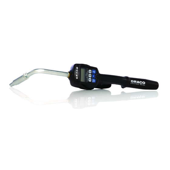
LDM5 (Standard) & LDP5 (Preset)
Electronic Metered Dispense Valves
- For metered dispense of oils and antifreeze -
Not for use in explosive atmosphere locations.
1000 psi (7 MPa, 69 bar) Maximum Working Pressure
5 gpm (19 lpm) Maximum Flow Rate
LDM5 Model 255751: Includes Flex Extension
LDM5 Model 256215: Includes Rigid Extension, Impact
Guard, Swivel Cover
LDP5 Model 255277: Includes Flex Extension
LDP5 Model 256216: Includes Rigid Extension, Impact
Guard, Swivel Cover
Important Safety Instructions
Read all warnings and instructions in this manual.
Save these instructions.
LDM5 Model 255751
ti12062a
LDM5 Model 256215
ti12063a
Patent Nos.
6,357,300*
D382,500
6,047,906
*Applies to LDP5 Preset Electronic Dispense Valve Only
1
NOTICE
This dispense valve:
•
is designed to dispense petroleum-based lubricants
and antifreeze only. Do not dispense windshield
washer solvent with this dispense valve.
•
is designed for indoor use only.
•
is not designed for in-line installation.
LDP5 Model 255277
ti12064a
312668D
77664
ZL97102971.7*
1025804
LDP5 Model 256216
ti12065a
Advertisement
Table of Contents

Related Manuals for Graco 255751


Summary of Contents for Graco 255751
- Page 1 Patent Nos. 5 gpm (19 lpm) Maximum Flow Rate 6,357,300* 77664 D382,500 ZL97102971.7* LDM5 Model 255751: Includes Flex Extension 6,047,906 LDM5 Model 256215: Includes Rigid Extension, Impact 1025804 Guard, Swivel Cover *Applies to LDP5 Preset Electronic Dispense Valve Only LDP5 Model 255277: Includes Flex Extension...
- Page 2 Warnings Warnings The following warnings are for the setup, use, grounding, maintenance, and repair of this equipment. The exclama- tion point symbol alerts you to a general warning and the hazard symbol refers to procedure-specific risk. Refer back to these warnings. Additional, product-specific warnings may be found throughout the body of this manual where applicable.
-
Page 3: Typical Installations
NOTICE . 1 shows a typical hose reel installation. Dispense • Do not use this dispense valve on non-Graco con- valves can also be installed on a console as shown in soles. The trigger could be inadvertently pressed Fig. 2. -
Page 4: Pressure Relief Procedure
Installation Pressure Relief Procedure Pre–Installation Procedure 1. Install the battery. See Replacing the Battery on page 28. 2. Follow the Pressure Relief Procedure. The equipment stays pressurized until pressure is man- 3. Close the shut–off valve (B, F . 1, page 3). ually relieved. - Page 5 Installation Connecting Hose to Meter a. Place the hose end (with no dispense valve connected) into a container for waste oil. b. Secure the hose in the container so it will not hose come out during flushing. fitting c. If you have multiple dispense positions, first flush the dispense position farthest from the pump, then work your way toward the pump.
- Page 6 Installation Installing Extension and Nozzle on Meter ti12081a ti12062a 4. Open all dispense position shut-off valves (B, F . 7) and start the pump to pressurize the system. See Operation, (LDM5 Meters - page 11; LDP5 Meters - page 20), for proper operation of meter. •...
- Page 7 LDM5 Meter Setup and Operation Instructions LDM5 Meter Setup and Operation Instructions Setup Terms Keypad Buttons (F . 8) The following terms are shown on the display and/or used often in this instruction manual. • R-TOTAL: Resettable Total Shows the cumulative amount that has been dis- pensed.
- Page 8 LDM5 Meter Setup and Operation Instructions Setup Menus (F . 9) c. Press and hold Reset button again to display Calibration Menu. When this menu is displayed CAL blinks on the screen (F . 12). LITERS The total that is displayed when you leave each AUTO R-TOTAL menu is the total that is stored.
- Page 9 LDM5 Meter Setup and Operation Instructions Resettable Total (F . 10) Units of Measurement (F . 11) Resets dispensed total on screen to zero or stores dis- Sets unit of measurement to quarts, gallons, pints, or played dispense total. The resettable total accumulates liters.
- Page 10 LDM5 Meter Setup and Operation Instructions Calibration (F . 12) b. Press and hold Total button until CAL stops Recalibrates the meter for dispensing different fluids. blinking. c. When CAL starts to blink again, the display should show 1.00. The new calibration is com- plete.
-
Page 11: Operation
LDM5 Meter Setup and Operation Instructions Operation Dispensing Fluid in Standard Mode 3. Squeeze the trigger. All buttons are disabled while fluid is being dis- pensed. Fluid begins to flow, and the amount shown on the display counts up from zero. LITERS AUTO R-TOTAL... - Page 12 LDM5 Meter Setup and Operation Instructions Viewing Totals This is the procedure for viewing the non–resettable and resettable totals in gallons or liters. To change the reset- table total, see Resettable Total, page 9. LITERS 1. If display is blank (in sleep AUTO R-TOTAL mode), press and hold either...
-
Page 13: Error Code
LDM5 Meter Setup and Operation Instructions Error Code If an error code is shown on the display, as shown in F . 18, you can press the Reset button to clear the error code and view the dispensed amount. Even in an error condition, the unit keeps LITERS AUTO... - Page 14 LDP5 Meter Setup and Operation Instructions LDP5 Meter Setup and Operation Instructions Setup Locking and Unlocking the Trigger Terms The following terms are shown on the display and/or used often in this instruction manual. • R-TOTAL: Resettable Total Shows the cumulative amount that has been dis- pensed in all modes.
- Page 15 LDP5 Meter Setup and Operation Instructions Keypad Buttons (F . 21) Setup Menus (F . 22) LITERS LITERS AUTO AUTO R-TOTAL R-TOTAL ti12052a ti12053a . 21 . 22 • Manual / Reset* 1. If the display is blank (asleep), Used to select Manual Mode dispensing (see wake it up by pressing any Terms).
- Page 16 LDP5 Meter Setup and Operation Instructions c. Press and hold the Auto / Reset button again to Resettable Total (F . 23) display the Calibration Menu (F . 25, page 17). Resets the dispense total to zero or stores the displayed When this menu is displayed CAL will blink on dispense total.
- Page 17 LDP5 Meter Setup and Operation Instructions Units of Measurement (F . 24) Calibration (F . 25) Sets the units of measurement to gallons, quarts, pints, Recalibrates the meter for dispensing different fluids. or liters. LITERS R-TOTAL LITERS AUTO R-TOTAL ti12056a ti12055a .
- Page 18 LDP5 Meter Setup and Operation Instructions b. Press and hold the 3. Do ONE of the following. Manual / Reset button a. To enter a new auto pre- until CAL stops blink- ing. set amount press and hold the 10 button to c.
- Page 19 LDP5 Meter Setup and Operation Instructions Shut–Off Default Amount (F . 27) 3. Do ONE of the following. Prevents accidental overfills when dispensing with the a. To enter a new shut–off trigger locked in Manual mode. The shut–off default default amount, press and amount is factory preset at 5 quarts.
- Page 20 LDP5 Meter Setup and Operation Instructions Operation Fluid flows, and the amount displayed counts up from zero or the previously dispensed amount. 4. Release/unlock the trigger when you have dis- LITERS pensed the desired amount of fluid. AUTO R-TOTAL Fluid flow stops. The amount you have dispensed is dis- played.
- Page 21 LDP5 Meter Setup and Operation Instructions Dispensing Fluid in Auto Mode (F . 29) a. Press and hold the Auto/Reset button to set the display to zero. LITERS AUTO R-TOTAL b. Press the10 button to change the 10s digit, press the 1.0 button to ti12057a change the 1s digit, .
- Page 22 LDP5 Meter Setup and Operation Instructions Viewing Totals Non-Resettable Totals This is the procedure for viewing the non–resettable and resettable totals. To change the resettable total, see Resettable Total on page 16. LITERS 1. If the display is blank (asleep), AUTO R-TOTAL press and hold the Man-...
-
Page 23: Error Codes
LDP5 Meter Setup and Operation Instructions Error Codes Error codes are listed below. Even in an error condition, the unit keeps track of the amount dispensed. With any LITERS error code displayed, as shown at right, you can: AUTO R-TOTAL •... -
Page 24: Troubleshooting
1.Relieve the pressure. 2.Clean or replace the filter. See Replacing the Filter, page 28. 3.If the problem remains, contact your Graco distributor for repair or replace- ment. Pump pressure is low. Turn up pump pressure. Shut–off valve is not fully open. - Page 25 Damaged valve stem assembly. Replace or clean valve stem and O-rings. Order Valve Repair Kit 240453. Poor seal at meter housing plate. Contact your Graco distributor for repairs or replacement. NOTE: Place a straight edge along meter housing plate. If flat, plate and seal are ok.
- Page 26 Part No. Description Part No. Description 255861 KIT, nozzle, flex, extension, for oil 255806 CONTROL, electronic, LDM5, and anti-freeze, includes 26a - 26c includes 15M845, models 255751, (models 255751, 255277) 256215 239949 KIT, nozzle, rigid, extension, for oil 255807 CONTROL, electronic, LDP5,...
- Page 27 Parts Models 256215, 256216 26: Rigid Extension 26: Flex Extension Models: 255751 and 255277 ti11970b Torque to 7 to 10 in.-lb (0.8 to 1.1 N•m) Torque to 140 to 150 in.-lb (16 to 17 N•m) Apply lubricant when reassembling Torque to 20 to 25 ft-lb (27 to 34 N•m)
-
Page 28: Replacing The Battery
Service Service Replacing the Battery Security Seal NOTICE Do not change the battery while anything is shown on the display. You must wait until the unit falls asleep and the display is blank before you remove the bat- tery. If you remove the battery while something is shown on the display, that information will be lost from memory. -
Page 29: Technical Data
Technical Data Technical Data Flow range* 01 to 5 gpm (0.4 to 19 lpm) Maximum Working Pressure 1000 psi (69 bar) Units of Measure pints, quarts, gallons, liters (factory set to quarts) Weight 3 lbs (1.36 kg) Dimensions without extension/nozzle Length 11 inches (28 cm) Width... -
Page 30: Graco Information
Graco warrants all equipment referenced in this document which is manufactured by Graco and bearing its name to be free from defects in material and workmanship on the date of sale to the original purchaser for use. Graco will, for a period of five (5) years from the date of sale, repair or replace any non-electronic part of the equipment determined by Graco to be defective.