Graco PD44 Operation & Maintenance Manual
Metering valves and feed systems
Hide thumbs
Also See for PD44:
- Setup and operation (48 pages) ,
- Operations & parts list (42 pages) ,
- Instructions manual (36 pages)
Table of Contents
Advertisement
Quick Links
Operation - Maintenance
PD44
Metering Valves and Feed Systems
Meter, mix, and dispense system for precise two-component micro-dispensing of sealants
and adhesives.
Not approved for use in European explosive atmosphere locations.
Important Safety Instructions
Read all warnings and instructions in this man-
ual. Save these instructions.
See page 3 for model information, including maximum
working pressure and approvals. See page 7 for prod-
uct configuration information.
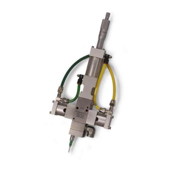
Linear Resistive Transducer PD44 Meter-
ing Valve shown, Feed Systems not shown
313876L
EN
Advertisement
Table of Contents

Related Manuals for Graco PD44


Summary of Contents for Graco PD44
- Page 1 Read all warnings and instructions in this man- ual. Save these instructions. See page 3 for model information, including maximum working pressure and approvals. See page 7 for prod- uct configuration information. Linear Resistive Transducer PD44 Meter- ing Valve shown, Feed Systems not shown...
-
Page 2: Table Of Contents
Valve Mounting Diagram ....19 Graco Information ......42 Motor Mounting Diagram . -
Page 3: Related Manuals
100 (0.7, 7) 1200 (8, 83) 400 (2.8, 28) Micrometer 2000 (14, 138) 100 (0.7, 7) 1200 (8, 83) 400 (2.8, 28) Motor Driven If a custom PD44 is ordered, it will not be CE approved unless otherwise noted. 313876L... -
Page 4: Warnings
Warnings Warnings The following warnings are for the setup, use, grounding, maintenance, and repair of this equipment. The exclama- tion point symbol alerts you to a general warning and the hazard symbol refers to procedure-specific risk. Refer back to these warnings. Additional, product-specific warnings may be found throughout the body of this manual where applicable. - Page 5 Warnings WARNING ELECTRIC SHOCK HAZARD This equipment must be grounded. Improper grounding, setup, or usage of the system can cause elec- tric shock. • Turn off and disconnect power cord before servicing equipment. • Use only grounded electrical outlets. • Use only 3-wire extension cords.
-
Page 6: Isocyanate Conditions
• Keep the ISO lube pump reservoir (if installed) filled atomized particulates. ™ with Graco Throat Seal Liquid (TSL ), Part 206994. Read material manufacturer’s warnings and material The lubricant creates a barrier between the ISO and MSDS to know specific hazards and precautions the atmosphere. -
Page 7: Product Configurator
C - A - BCD -EFG- H - I - J - K - L - M - NO - P - Q - RS - T - U - V - W - X The following table applies to the PD44 configurations and indicates all of the options available for each letter shown above. - Page 8 Product Configurator Code E Part Low Volume Rod Material Code H Part High Volume Spool NOTE: See code FG for last two digits of part number 964003 High viscosity, HS 9641__ Hardened Steel 964004 High viscosity, Stainless Steel/UHMWPE 9642__ Stainless Steel, UHMW 964005 High viscosity, TC/UHMWPE 9643__ Tungsten Carbide, UHMW 964006 Low viscosity, Stainless Steel...
- Page 9 Product Configurator Code L Part Controls Code P Part High Volume Feed Hose 964035 Pneumatic, micrometer, wire harness 964082 1/2 in. x 8 ft PTFE and stainless steel only hose, stainless steel fittings 964036 Pneumatic, micrometer, HMI controls, 964084 1/2 in. x 10 ft PTFE and stainless steel low level hose, stainless steel fittings 964037 Pneumatic, micrometer, HMI controls,...
-
Page 10: Accessories
Accessories Accessories Mixer Kits with Shroud Part Description 964034 Mixer, Kit, 3/16 in. (4.8mm) x 24, 10 taper tip mixers with shroud 964032 Mixer, Kit, 3/16 in. (4.8mm) x 32, 10 taper tip mixers with shroud 964028 Mixer, Kit, 3/16 in. (4.8mm) x 32, 10 Luer Lock tip mixers with shroud/sleeve 964033 Mixer, Kit, 1/4 in. - Page 11 O-Rings and Seals Part Description Part Description 16B286 Seal, Posipack, 4.50, ZAP 24E247 Kit, O-ring, chemical resistant, PD44 16B287 Seal, Posipack, 4.63, ZAP 24E248 Kit, Seal, Spool, H.V., PD44 16B288 Seal, Posipack, 4.75, ZAP 24E249 Kit, Seal, Spool, L.V., PD44 16B289 Seal, Posipack, 4.88, ZAP...
-
Page 12: Grounding
Grounding Grounding This product must be grounded. In the event of an elec- trical short circuit, grounding reduces the risk of electric shock by providing an escape wire for the electric cur- rent. Metering valve: attach ground wire from grounding lug to true earth ground. -
Page 13: Component Identification
Component Identification Component Identification Typical System Configurations Base Unit B Side Feed A Side Feed Controls WARNING Do Not service without removing air pressure and waring saftey glasses. Liquid Control Corp. 8400 PORT JACKSON AVE. N.W. NORTH CANTON, OH 44720 USA SERIAL MODEL NUMBER... -
Page 14: Typical Feed System Components
Component Identification Typical Feed System Components 5 Gallon Pail Cover 5 Gallon Pail Cover with Diaphragm with Diaphragm Pump Pump and Agitator 20 oz Cartridge Feed with Mounting Post 1 Gallon Ram and Pump WARNING DO NOT SERVICE WITHOUT REMOVING AIR PRESSURE AND WEARING SAFETY GLASSES. -
Page 15: Micrometer Pd44 Metering Valve
Component Identification Micrometer PD44 Metering Valve Side View Front View Key: A Material Inlet (1/4 NPT) Extend Air Flow Adjustment B Material Inlet (1/4 NPT) Knob Grounding Lug Retract Air Flow Adjustment Spool Assemblies Knob Metering Rods Retract Proximity Switch... -
Page 16: Lrt Pd44 Metering Valve
Component Identification LRT PD44 Metering Valve Side View Front View Key: A Material Inlet (1/4 NPT) Reload Air Inlet B Material Inlet (1/4 NPT) Extend Air Flow Adjustment Grounding Lug Knob Spool Assemblies Retract Air Flow Adjustment Metering Rods Knob... -
Page 17: Motor Driven Pd44 Metering Valve
Component Identification Motor Driven PD44 Metering Valve Side View Front View Key: A Material Inlet (1/4 NPT) Retract Air Flow Adjustment B Material Inlet (1/4 NPT) Knob Grounding Lug Over-travel Proximity Switch Spool Assemblies Home Proximity Switch Metering Rods Spool Valve Proximity Switch... -
Page 18: Setup
Setup Setup NOTE: See Typical Installation diagram. 4. On the Motor Driven PD44, if a non-Graco motor is used, install the motor onto the metering valve. See 1. Perform Setup procedure for feed system compo- Motor Mounting Diagram, page 20. -
Page 19: Tank Level Sensor Wiring Schematic
Setup Tank Level Sensor Wiring Schematic TANK LEVEL PIN USAGE USAGE NUMBER HIGH BROWN BLACK HIGH BLUE HIGH BROWN BLACK BLUE BLUE JUMPER PIN 6 AND 7 24 VDC+ SIGNAL TYPICAL LEVEL SENSOR WIRING Valve Mounting Diagram As desired, use the following diagram to mount the metering valve. -
Page 20: Motor Mounting Diagram
Setup Motor Mounting Diagram If using a non-Graco motor with the Motor Driven PD44, use the following diagram to install the non-Graco motor onto the Motor Driven PD44 metering valve. See Motor Specifications, page 40. 2.22 2.039 0.182 0.182 Ø 0.251 STANDARD 2.039... -
Page 21: Startup
Startup Startup 1. Fill the spool valve ports with compatible lubricant. 5. Dispense several full stroke shots until material is Consult with your material supplier to select an air-free and has good shut-off at the nose. acceptable lubricant. Regularly verify that lubricant NOTE: Very viscous, compressible materials may con- is present. -
Page 22: Adjusting The Shot Size
LRT and Motor Driven PD44 On LRT and Motor Driven PD44s, shot size is controlled by the PD44 Control Box. See the PD44 Control Box manual. See Related Manuals on page 3. 3. Rotate the shot size locking ring clockwise to tighten. -
Page 23: Ratio Check
Ratio Check Ratio Check Perform ratio check procedure at startup and after 8. Subtract weight of empty cups from weight of filled rebuild. cups to get material weights. 9. Complete ratio calculations. 1. Weigh six small cups and label as indicated. Record weights. -
Page 24: Operation
Operation Step 3: Dispense The operation of the PD44 metering valve is controlled by an external source. If a PD44 Control Box was pur- chased, see the PD44 Control Box manual for operation instructions. See Related Manuals on page 3. -
Page 25: Pressure Relief Procedure
Pressure Relief Maintenance Procedure Perform the following procedures once a shift. 1. Retract the metering rods. See the PD44 Control NOTE: If material is leaking, see Troubleshooting on Box manual. See Related Manuals on page 3. page 26. 2. Close both the A side and B side fluid shut-off Material Reservoirs valves. -
Page 26: Troubleshooting
Check mixer for cured material, dispensing replace mixer Schematics For standard machines, the schematics will be included in the PD44 Parts manual. See Related Manu- als on page 3. For custom machines, the schematics will be included in the assembly drawings manual. 313876L... -
Page 27: Rebuild
Rebuild Rebuild 6. Loosen set screws on top of the connecting block. Wetted Section Disassembly 7. Slide the metering rod retaining plate until the larger hole position is in-line with the metering rod. See . 11 in the following step. 8. - Page 28 Rebuild 11. Remove the four cap screws located at the top of 14. Remove the two tubes. Always keep rods and tubes the oil cup retaining block. together as they are a matched set. Oil Cup Retaining Block Tube 15. Remove the protruding cap screws on each spool block.
-
Page 29: Wetted Section Reassembly
Wetted Section Reassembly 1. Install the pneumatic spool rod drive. Torque fasten- ers to 67-70 in-lb (7.5-7.9 N•m). Micrometer PD44 shown 5. Attach the front plate to the serial number side of the metering body. 6. On Micrometer and LRT PD44s, ensure the air inlet ports are pointed towards the front plate. -
Page 30: Spool Valve Rebuild
Rebuild 11. Manually move connecting block up and down to Spool Valve Rebuild insure rods are properly installed. 12. Install the back plate and cap screws. Back Plate 1. Perform Wetted Section Disassembly, page 27. 2. Remove the two cap screws. Cap Screws Cap Screws 13. -
Page 31: Wetted Section Rebuild
Rebuild 6. Insert new o-ring into spool air cylinder end cap. 2. Remove spool rods and sleeves from the metering block. 7. Install proximity switch. 8. Apply Krytox or compatible lubricant to cylinder. 9. Insert piston into cylinder with the u-cup lip pointed in the direction of the tapered end of the cylinder. - Page 32 Rebuild 6. For each pneumatic drive spool block, install new NOTE: Correct orientation of seals shown. zap seals and o-rings onto o-ring retainer. Low Viscosity Spool Sleeve Seals Low Viscosity Spool High Viscosity Spool Sleeve Cutout View 11. Carefully install the spool sleeves into the metering block.
- Page 33 Rebuild 12. Apply Krytox to spool rod then carefully install the 17. Install the wetcup sleeve onto the metering sleeve. spool rod into the spool sleeve (inside the metering block). Make sure not to cut the spool sleeve zap seals (on low viscosity spools). Wetcup Sleeve 18.
-
Page 34: Micrometer Drive Rebuild (Micrometer Pd44 Only)
Rebuild Micrometer Drive Rebuild 5. Slide the pneumatic drive piston off the drive rod. (Micrometer PD44 Only) 1. Perform Wetted Section Disassembly, page 27. 2. Remove the four cap screws located at the top of the pneumatic drive assembly. 6. Slide the air cylinder mounting block off the drive Cap Screws rod. - Page 35 Rebuild 9. Install new posipak seal with the o-ring pointed 13. Slide the drive rod into the closed slot in the piston. towards the drive piston, then install washer and retaining ring. 14. Install the cylinder o-ring then, careful not to cut the piston seal, install the drive rod into the block.
-
Page 36: Electrical Requirements
Electrical Requirements Electrical Requirements Electrical requirements for pneumatically driven and PD44 metering valve only: Wiring harness sensors are stepper driven control boxes can be found in the PD44 24 VDC normally open PNP. See F . 12, F . 13, or Control Box manual. - Page 37 Electrical Requirements . 13: Motor Driven PD44 Metering Valve Electrical Requirements 313876L...
- Page 38 Electrical Requirements . 14: LRT PD44 Metering Valve Electrical Requirements 313876L...
-
Page 39: Technical Data
Sound Data* ........PD44 Metering Valve:... -
Page 40: California Proposition 65
Technical Data Motor Specifications If a non-Graco motor is used with the Motor Driven Torque at Maximum Speed: 117 oz-in (7.3 in-lb) at 20 PD44 Metering Valve, it must meet the following specifi- revolutions per second (1 in. of rod travel per second). - Page 41 Technical Data 313876L...
-
Page 42: Graco Standard Warranty
With the exception of any special, extended, or limited warranty published by Graco, Graco will, for a period of twelve months from the date of sale, repair or replace any part of the equipment determined by Graco to be defective.