Table of Contents
Advertisement
Quick Links
Installation, Operation, and Maintenance
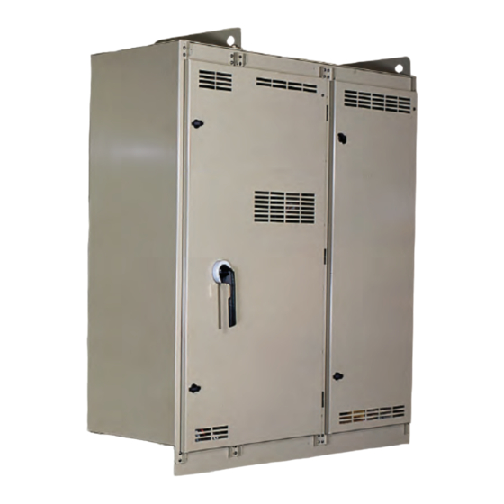
Liquid-Cooled Adaptive
Frequency™ Drive
with Tracer® AdaptiView™ Control
Models
Only qualified personnel should install and service the equipment. The installation, starting up, and servicing of
heating, ventilating, and air-conditioning equipment can be hazardous and requires specific knowledge and training.
Improperly installed, adjusted or altered equipment by an unqualified person could result in death or serious injury.
When working on the equipment, observe all precautions in the literature and on the tags, stickers, and labels that are
attached to the equipment.
June 2020
AFDE
AFDE-SVU02F-EN
SAFETY WARNING
X39641074060
Advertisement
Table of Contents

Related Manuals for Trane Liquid-Cooled Adaptive Frequency AFDE

Summary of Contents for Trane Liquid-Cooled Adaptive Frequency AFDE
- Page 1 Installation, Operation, and Maintenance Liquid-Cooled Adaptive Frequency™ Drive with Tracer® AdaptiView™ Control Models AFDE X39641074060 SAFETY WARNING Only qualified personnel should install and service the equipment. The installation, starting up, and servicing of heating, ventilating, and air-conditioning equipment can be hazardous and requires specific knowledge and training. Improperly installed, adjusted or altered equipment by an unqualified person could result in death or serious injury.
- Page 2 10 minutes for capacitors to discharge. compounds have the same potential impact to the • All electrical enclosures—unit or remote—are IP2X. environment. Trane advocates the responsible handling of all refrigerants-including industry replacements for CFCs • Customers are responsible for all field wiring in...
- Page 3 WARNING This document and the information in it are the property of Personal Protective Equipment (PPE) Trane, and may not be used or reproduced in whole or in Required! part without written permission. Trane reserves the right to revise this publication at any time, and to make changes Failure to wear proper PPE for the job being undertaken could result in death or serious injury.
-
Page 4: Table Of Contents
... . . 13 Surge Detection .....41 Identifying Trane AFDE Cabinet Components UC800 Interface to Adaptive Frequency Drive Drive Cabinet Component Locations . -
Page 5: General Information
Parts Ordering Information Refer to the model number printed on the Trane Adaptive Frequency Drive nameplate when ordering replacement parts or service for the drive. When ordering parts, contact the local Trane Parts Office in your area. For service, X39003893001A contact a qualified service organization. -
Page 6: Motor Checks
General Information If a short circuit exists, it must be corrected before proceeding. WARNING Controller Checks Capacitors Must Be Allowed To Discharge! 4. Check that local, state and national electric codes have Failure to disconnect power and discharge capacitors been observed for the installation and wiring of this before servicing could result in death or serious injury. -
Page 7: Safety Precautions
General Information WARNING WARNING Hazardous Voltage! Proper Field Wiring and Grounding Required! Failure to ensure that all enclosure doors are closed and properly secured with fasteners when operating Failure to follow code could result in death or serious equipment could result in death or serious injury. injury. - Page 8 Follow proper lockout/ tagout procedures to ensure the power cannot be inadvertently energized. For variable frequency drives or other energy storing components provided by Trane or others, refer to the appropriate manufacturer’s literature for allowable waiting periods for discharge of capacitors.
-
Page 9: Overview
Overview voltage motor terminal box cover must not be removed if power is present, or if there is a possibility that power may WARNING be present. Working on energized medium voltage circuits is not an approved practice for normal HVAC maintenance Hazardous Service Procedures! or service. -
Page 10: Ce For Afde Drives
Important: • All Trane-supplied drives must be used with CVHH or CDHH Trane chillers to ensure CE compliance. • Basic drive details are provided on drive nameplate. Please refer to the chiller unit nameplate located on the... -
Page 11: Afde Information
This manual covers the features and specifications that are protective device upstream of all drives in accordance with unique to the Trane Adaptive Frequency Drives being IEC standards and/or any applicable national and local and produced for Trane. Only product information is covered codes. -
Page 12: Model Number Descriptions
Addition of 405 Amp Drive No Common Mode Cores Common Mode Cores C0 = Vendor Component Change D0 = Addition of 900 Amp Drive E0 = Revise RECOMM-TRANE Software F0 = Tyco Connector/Harness G0 = Precharge Resistor H0 = I/F PCBA Connector Change... -
Page 13: Drive And Cabinet
Drive and Cabinet Enclosure Rating Identifying Trane AFDE Cabinet Components The Trane® cabinet has a NEMA 1 enclosure rating: NEMA 1: Vented. Intended for general-purpose indoor Trane AFDE cabinets have the following main applications. components. For convenience, the drive is discussed in two sections, a rectifier (input) and inverter (output) sections. - Page 14 Drive and Cabinet 23. Line Sync, PCB Assembly 24. Line Sync, PCB Cover 25. Terminal Block, Fans, 6-Position 26. Surge Suppressor 27. OIM Note: OIM is mounted inside panel for design sequence P0 and earlier. OIM is mounted outside panel for design sequence R0 and later. AFDE-SVU02F-EN...
- Page 15 Drive and Cabinet Figure 1. Drive components locations: Frame 3 units User-Supplied Motor Leads L1 L2 AFDE-SVU02F-EN...
- Page 16 Drive and Cabinet Figure 2. Magnetic choke Enclosure Note:Cores are only used when compressor has steel bearings. AFDE-SVU02F-EN...
-
Page 17: Power Module Component Locations
Drive and Cabinet Power Module Component Locations Frame 3 Units LF200405AAP and LF200608CCP The main power module components for a Frame 3 unit are listed below. Each numbered item corresponds to a number in Figure 3, p. 18 Figure 4, p. 1. - Page 18 Drive and Cabinet Figure 3. Power module component locations door open: Frame 3 units AFDE-SVU02F-EN...
- Page 19 Drive and Cabinet Figure 4. Power module component locations door closed: Frame 3 units AFDE-SVU02F-EN...
-
Page 20: Drive Cabinet Component Locations
Drive and Cabinet Drive Cabinet Component Locations Frame 4 Units 180180-A07 and 180180-A09 The main drive components for a Frame 4 unit are listed below. Each numbered item corresponds to a number in Figure 5, p. 1. Circuit Breaker, 600V 2. - Page 21 Drive and Cabinet Figure 5. Drive component locations: Frame 4 units L1 L2 L3 Note: Units with CE certification include touch-safe barriers (not shown). AFDE-SVU02F-EN...
- Page 22 Drive and Cabinet Figure 6. Magnetic choke Enclosure Note: Cores are only used when compressor has steel bearings. AFDE-SVU02F-EN...
-
Page 23: Power Module Component Locations
Drive and Cabinet Power Module Component Locations Frame 4 Units LF200900CCP and LF201215CCP The main power module components for a Frame 4 unit are listed below. Each numbered item corresponds to a number in Figure 7, p. 24 Figure 8, p. 1. - Page 24 Drive and Cabinet Figure 7. Power module component locations IO and control panel removed: Frame 4 units AFDE-SVU02F-EN...
- Page 25 Drive and Cabinet Figure 8. Power module component locations front panel removed: Frame 4 units AFDE-SVU02F-EN...
-
Page 26: About The Cabinet
Drive and Cabinet About the Cabinet This section provides cabinet dimension information and shows where the wire entry areas and liquid-cooling connection points are located. Figure 9, p. 26 shows overall dimensions for Frame 3 units Figure 10, p. 27 shows overall dimensions for Frame 4 units. - Page 27 97.79 26.00 (660.4) (2483.9) 67.77 8.43 8.02 23.00 (584.2) (1721.4) (214.1) (203.7) (4.57 [116.1]) 8.10 (205.7) 2.38 (60.5) TRANE AFD LOGO 75.11 (1907.5) 2.93 (74.4) 70.36 BACK OF (1787.1) CHILL PLATES 33.0 (838.2) 2.61 (66.3) 5.00 (127.0) 25.00 (635) WARNING HAZARDOUS VOLTAGE...
-
Page 28: Drive Removal
Follow proper lockout/ tagout procedures to ensure the power cannot be inadvertently energized. For variable frequency drives or other energy storing components provided by Trane or others, refer to the appropriate manufacturer’s literature for allowable waiting periods for discharge of Service isolation valves capacitors. -
Page 29: Lifting The Drive
Drive and Cabinet 6. Loosen and remove the bolts that secure the Re-assembly of the drive is essentially the reverse of the refrigerant line flanges to the drive flanges. Take care above procedure. The drive enclosure to mounting bracket not to misplace any orifice plates that may be installed bolts should be torqued to 90 ft·lb (122 N·m). - Page 30 Drive and Cabinet Frame 3 drives (608 Amp and 405 Amp) have an orifice Figure 12. Lift point locations for LiquiFlo 2.0 drives plate located between the inlet flange and the heat sink. Lift Points The orifice plate sits between two gaskets. Frame 3 Frame 4 drives have no orifice plate.
-
Page 31: Input Power And Control Wiring
For variable frequency drives 4. Install the appropriate conduit hubs. or other energy storing components provided by Trane 5. Reinstall the cabinet’s top panel. or others, refer to the appropriate manufacturer’s literature for allowable waiting periods for discharge of 6. -
Page 32: Installing External 120 Vac Control Power
Input Power and Control Wiring b. For CE units, connect the input power leads to the L1, L2, and L3 terminals located before the EMC line Table 3. Torque value for AFDE output to motor filter. FLEXIBAR (flexible insulated busbar) 7. -
Page 33: Grounding The Cabinet
Input Power and Control Wiring Important: • Before servicing, disconnect all power sources and WARNING allow at least 10 minutes for capacitors to discharge. Hazardous Voltage/Improper Grounding! • All electrical enclosures-unit or remote-are IP2X. Hazardous voltage due to improperly grounded electrical components could result in death or serious injury. - Page 34 Input Power and Control Wiring WARNING Proper Field Wiring and Grounding Required! Failure to follow code could result in death or serious injury. All field wiring MUST be performed by qualified personnel. Improperly installed and grounded field wiring poses FIRE and ELECTROCUTION hazards. To avoid these hazards, you MUST follow requirements for field wiring installation and grounding as described in NEC and your local/state electrical codes.
-
Page 35: Afde Cooling Circuit
AFDE Cooling Circuit The AFDE Adaptive Frequency Drive is cooled with liquid A small orifice is installed in the lower flange inlet at the refrigerant from the chiller. The refrigerant pump on the drive. The purpose of the orifice is to regulate the amount chiller takes refrigerant from the condenser sump and of refrigerant that enters the drive. -
Page 36: Liquid-Cooling Connections
Liquid-Cooling Connections Factory Connected on Unit Mounted Drives WARNING Contains Refrigerant! System contains oil and refrigerant and may be under positive pressure. Recover refrigerant to relieve pressure before opening the system. See unit nameplate for refrigerant type. Do not use non- approved refrigerants, refrigerant substitutes, or refrigerant additives. - Page 37 Liquid-Cooling Connections Refrigerant coolant lines connect to the cabinet through flange fittings located on the rear of the cabinet. A panel must be removed to provide access to the flange connections. If you have removed the refrigerant cooling lines for field disassembly or repairs use the following steps to re-connect the coolant lines to the cabinet (see Figure 14).
-
Page 38: Uc800 Afd Operation
UC800 AFD Operation Adaptive Frequency Drive Control compressor speed to achieve a desired compressor loading command while holding a fixed margin of safety between the compressor operating point and compressor Introduction surge. In order to quantify nearness to surge, a non- Achieving Efficiency dimensional parameter called “compressor pressure coefficient”... -
Page 39: Afd Speed Control
UC800 AFD Operation Figure 15. Pressure coefficient surge boundary Surge Boundary Surge 100.0 10.0 20.0 30.0 40.0 50.0 60.0 70.0 80.0 90.0 IGV Position AFD Speed Control UC800 control utilizes an enhanced control method capable of simultaneously adjusting compressor speed and inlet guide vane position to achieve the desired chiller capacity and pressure coefficient. -
Page 40: Re-Optimization
UC800 AFD Operation Figure 16. Startup surge boundary Pressure Coefficient Trajectory Start to Full Load Running surge boundary Full load Boundary increases by 0.1 after 30 minutes Surge boundary for start up 100.0 10.0 20.0 30.0 40.0 50.0 60.0 70.0 80.0 90.0 IGV % Capacity... -
Page 41: Surge Recovery
UC800 AFD Operation Figure 17. Boundary re-optimization Pressure Coefficient Optimization Surge detected 100.0 10.0 20.0 30.0 40.0 50.0 60.0 70.0 80.0 90.0 IGV % Capacity Surge Recovery Surge Detection When surge occurs, the pressures in the evaporator and Surge detection control logic monitors changes in condenser shells can become erratic. -
Page 42: Uc800 Interface To Adaptive Frequency Drive
UC800 AFD Operation UC800 Interface to Adaptive Frequency Output contacts are required to control the load of the refrigerant/oil pump motor and the cooling circulating Drive pump. The contacts are Normally Open, and closed when the AFD energizes the motor. Communications between the UC800 and the AFD are handled via the Machine Bus Note: Unlike locked rotor amps associated with... -
Page 43: Service Interface
Adjustable Frequency Drive (AFD). For the for advanced troubleshooting. For more information on operator’s day-to-day operational information, Tracer® Tracer® TU, visit your local Trane Service company, or AdaptiView™ displays data (English or SI units) Trane‘s website at www.Trane.com. - Page 44 Service Interface Table 8. Tracer TU: Service Setpoints view: Adjustable Frequency Drive Setpoints section Description Factory Default Units AF Control (Auto, Fixed) Auto Re-Optimization Sensitivity Percent Notes: 1. Use only Factory Defaults. Defaults other than above may effect chiller reliability 2.
- Page 45 (a) Use only the factory settings for this application as they are specific to the sales order. Instability and faults may occur by using other settings and is not recommended. Contact your local Trane Representative for service when necessary. AFDE-SVU02F-EN...
-
Page 46: Troubleshooting
Troubleshooting Alarms • Unknown (lowest priority and displays last) Active alarms are followed by any historical alarms. These When an active alarm is present, it is identified in the appear gray on the screen. The alarms button at the Active Alarms area in the upper left corner of the Tracer bottom of the screen flashes between two colors AdaptiView display. - Page 47 For variable frequency drives • Time since last diagnostic shutdown (<1 minute, or other energy storing components provided by Trane <1 hour, >1 hour, etc.) or others, refer to the appropriate manufacturer’s literature for allowable waiting periods for discharge of b.
-
Page 48: Alarm Messages And Fault Codes
Alarm Messages and Fault Codes The “AFD Last Diagnostic Code” value is available using Tracer TU. This value is located under the Unit Status tab, in the Motor expanding box. Table 12. Alarm messages and fault codes TU Last Tracer AdaptiView TU Last Tracer AdaptiView Alarm Diag Code... -
Page 49: Afde Startup Procedure
For variable frequency drives Contact CenTraVac™ Chiller Technical Support for or other energy storing components provided by Trane assistance if needed. or others, refer to the appropriate manufacturer’s literature for allowable waiting periods for discharge of capacitors. - Page 50 AFDE refrigerant-cooled drives. Note: If the set values do not match, contact the local Trane Service agency first, or, the La Crosse Business Unit Technical Service Department. The correct values are listed on the unit nameplate shipped with each unit.
-
Page 51: Startup Test Log
Power Loss Time Comments: Flying Start Disable Flying Start Gain 2000 Use Trane Defaults (for all other AFD parameters not accessible via Tracer TU) RTD Type *Must be set per sales order variable. Test Log Date: Log 1 Log 2... -
Page 52: Recommended Periodic Maintenance And Inspection
For variable frequency drives or other energy storing components provided by Trane 8. Closely inspect the motor terminal board for any signs or others, refer to the appropriate manufacturer’s of leakage, arcing, etc. -
Page 53: Operational Inspection-Power Applied
(OIM) and special cable are required. All UC800 chillers will be equipped with the OIM as standard on the drive power module. This is for service only and NEVER for machine operation. These items are available from Trane with the following part numbers: OIM (Operator Interface Module): MOD01352... -
Page 54: Wiring Schematics
For reference, an as-built schematic wiring diagram and a field wiring connection diagram are located inside the main control panel door of the chiller. Figure 21. Field connection diagram: CVHE, CVHF, CVHG —Trane-supplied Adaptive Frequency Drive (1 of 2) AFDE-SVU02F-EN... - Page 55 Wiring Schematics Figure 22. Field connection diagram: CVHE, CVHF, CVHG—Trane-supplied Adaptive Frequency Drive (2 of 2) AFDE-SVU02F-EN...
- Page 56 Wiring Schematics Figure 23. Field connection diagram: CVHH — Trane-supplied Adaptive Frequency Drive (1 of 2) AFDE-SVU02F-EN...
- Page 57 Wiring Schematics Figure 24. Field connection diagram: CVHH— Trane-supplied Adaptive Frequency Drive (2 of 2) AFDE-SVU02F-EN...
- Page 60 For more information, please visit trane.com or tranetechnologies.com. Trane has a policy of continuous product and product data improvement and reserves the right to change design and specifications without notice. We are committed to using environmentally conscious print practices.