Jet JPS-10TS Operating Instructions And Parts Manual
10-inch
Hide thumbs
Also See for JPS-10TS:
- Operating instructions and parts manual (40 pages) ,
- Brochure (2 pages) ,
- Specifications (2 pages)
Table of Contents
Advertisement
This Manual is Bookmarked
Operating Instructions and Parts Manual
10-inch Table Saw
Model JPS-10TS
R
C
US
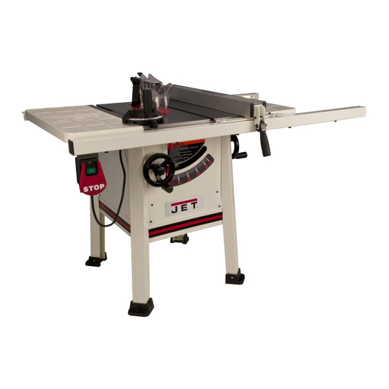
shown with optional mobile base #708119 (not provided)
WMH TOOL GROUP
2420 Vantage Drive
Elgin, Illinois 60124
Part No. M-708480
Ph.: 800-274-6848
Revision C 03/08
www.wmhtoolgroup.com
Copyright © WMH Tool Group
Advertisement
Table of Contents

Related Manuals for Jet JPS-10TS


Summary of Contents for Jet JPS-10TS
- Page 1 This Manual is Bookmarked Operating Instructions and Parts Manual 10-inch Table Saw Model JPS-10TS shown with optional mobile base #708119 (not provided) WMH TOOL GROUP 2420 Vantage Drive Elgin, Illinois 60124 Part No. M-708480 Ph.: 800-274-6848 Revision C 03/08 www.wmhtoolgroup.com...
- Page 2 WMH Tool Group is consistently adding new products to the line. For complete, up-to-date product information, check with your local WMH Tool Group distributor, or visit jettools.com. WARRANTY JET products carry a limited warranty which varies in duration based upon the product (MW = Metalworking, WW = Woodworking). WHAT IS COVERED? This warranty covers any defects in workmanship or materials subject to the exceptions stated below.
-
Page 3: Table Of Contents
Table of Contents Table of Contents... 3 Warning ... 4 Kickback Prevention... 6 Protection Tips from Kickback... 6 Features ... 7 Specifications ... 7 Definitions and Terminology... 8 Shipping Contents... 9 Assembly... 10 Unpacking and Cleanup ... 10 Installing Legs... 10 Blade Tilt Pointer ... -
Page 4: Warning
Warning 1. Read and understand the entire owner's manual before attempting assembly or operation. 2. Read and understand the warnings posted on the machine and in this manual. Failure to comply with all of these warnings may cause serious injury. 3. -
Page 5: Save These Instructions
blahblahblah 19. Provide for adequate space surrounding work area and non-glare, overhead lighting. 20. Keep the floor around the machine clean and free of scrap material, oil and grease. 21. Keep visitors a safe distance from the work area. Keep children away. 22. -
Page 6: Kickback Prevention
The most common accidents among table saw users, according to statistics, can be linked to kickback, the high-speed expulsion of material from the table that can strike the operator. Kickback can also result in operator’s hands being pulled into the blade. Kickback Prevention Tips to avoid the most common causes of kickback:... -
Page 7: Features
Features Figure 1 (mobile base purchased separately) Specifications Model Number... JPS-10TS ...JPS-10TS Stock Number ...708480 ... 708481 Blade Diameter (in.) ... 10 ... 10 Arbor Diameter (in.)... 5/8 ... 5/8 Maximum Depth of Cut (in.) ...3-1/8 ...3-1/8 Maximum Rip to Right of Blade (in.) ... 30 ... 30 Maximum Rip to Left of Blade (in.)... -
Page 8: Definitions And Terminology
Definitions and Terminology Arbor: Metal shaft that connects the drive mechanism to the blade. Bevel Edge Cut: Tilt of the saw arbor and blade between 0° and 45° to perform an angled cutting operation. Blade Guard: Mechanism mounted over the saw blade to prevent accidental contact with the cutting edge. -
Page 9: Shipping Contents
Shipping Contents Carton Contents (see Figure 2) 1 ea Table Saw (not shown) 1 ea Blade (not shown) 1 ea Extension Wing – Left (A) 1 ea Extension Wing – Right (B) 1 ea Dust Hood (C) 4 ea Legs (D) 4 ea Feet (E) 1 ea Miter Gauge (F) 1 ea Handwheel –... -
Page 10: Assembly
Handwheels Referring to Figure 7: The JPS-10TS Table Saw comes equipped with two handwheels which look identical except for the mounting holes as follows: 1. On the front of the table saw slide the bushing... -
Page 11: Extension Wings
3. Slide the remaining handwheel (E) with the smaller mounting hole onto the shaft (F) on the right side of the table saw, lining up the flat side in the hole with the flat side on the shaft. 4. Secure with an M5 lock washer (G) and M5x12 socket head cap screw (H). -
Page 12: Blade Guard And Splitter
Blade Guard and Splitter Referring to Figure 12: 1. Through the saw table opening on top, locate two hex nuts (A ) that secure two retaining plates (B) and loosen with a 10mm wrench. 2. Slide the tab of the blade guard splitter (C) between the two retaining plates (B) and onto the threaded mounting studs (D). -
Page 13: Table Insert
If alignment is required: 3. Move the straight-edge aside and through the opening (see inset) locate four hex nuts (F, G) and two retaining plates (H) that secure the splitter tab (J). 4. Slightly loosen the hex nuts (F, G). 5. -
Page 14: Grounding Instructions
Grounding Instructions 1. All Grounded, Cord-connected Tools: In the event of a malfunction or breakdown, grounding provides a path of least resistance for electric current to reduce the risk of electric shock. This tool is equipped with an electric cord having an equipment-grounding conductor and a grounding plug. -
Page 15: Extension Cord Recommendations
PD-LK-1 (Stock No. 709012) is available from your local authorized JET distributor or by calling JET Equipment & Tools at the phone number on the cover of this manual. Place the key in a location that is inaccessible to children and others not qualified to use the tool. -
Page 16: Adjustments
Adjustments Disconnect saw from power source before making adjustments. Blade Raising and Tilt Mechanism Never try to force the tilting mechanism past the 45º or 90º stops. This may cause the blade to go out of alignment. Referring to Figure 18: To raise or lower the saw blade, loosen the lock knob (A) and turn the handwheel (B) on the front of the saw until the desired height is reached. -
Page 17: Table To Blade Alignment
If adjustment is required: 10. Back out the 45º adjust setscrew (turn counterclockwise) one or two turns with a 4mm hex wrench (F, Fig. 20). 11. Turn the blade tilting handwheel until the blade is exactly 45º. 12. Tighten the 45º adjust setscrew until it stops, but do not force. -
Page 18: Operations
Operations (NOTE: The following Figures may or may not show your specific saw, but the procedures are the same.) Table Saws Familiarize yourself with the location and operation of all controls and adjustments and the use of accessories such as the miter gauge and rip fence. - Page 19 Rip Sawing Ripping is where the work piece is fed with the grain into the saw blade using the fence as a guide and a positioning device to ensure the desired width of cut (Figure 25). Figure 25 Before starting a ripping cut, be sure the fence is clamped securely and aligned properly.
- Page 20 When ripping long boards, use a support at the front of the table, such as a roller stand, and a support or "tailman" at the rear as shown in Figure 28. Never use the rip fence beyond the point where the carriage is flush with the end of the rails.
-
Page 21: Bevel And Miter Operations
To improve the effectiveness of the miter gauge in crosscutting, some users mount an auxiliary wooden extension face (with a glued-on strip of sandpaper) to the miter gauge as shown in Figure 32. Provide auxiliary support for any workpiece extending beyond the table top with a tendency to sag and lift up off the table. -
Page 22: Safety Devices
The use of a push block or push stick provides an added level of safety for the operator. See the templates in Figures 38 and 39 for construction details, or purchase one from the JET Woodworking Machinery and Accessories catalog. Figure 38 – Push Block Template Figure 36... -
Page 23: Maintenance
Always disconnect power to the machine before performing maintenance. Failure to do this may result in serious personal injury. Cleaning Clean the JPS-10TS according to the schedule below to ensure maximum performance. Note—The following maintenance schedule assumes the saw is being used every day. -
Page 24: Troubleshooting
Troubleshooting Symptom Possible Cause Motor will not start Low voltage. Open circuit in motor or loose connection. Motor will not start: fuses Short circuit in line cord or plug. or circuit breakers blow. Short circuit in motor or loose connections. Incorrect fuses or circuit breakers in power line. -
Page 25: Motor And Trunnion
31 ...JWTS10-131 ...Blade ... 10”x5/8”x28T... 1 32 ...JWTS10-132 ...Flange ..1 33 ...JWTS10-133 ...Arbor Nut... 5/8”-12... 1 34 ...LM000629 ...JET Label ..1 35 ...TS-1522011 ...Set Screw... M5x6 ... 2 36 ...JPS10TS-136...Fixing Ring ..1 37 ...JPS10TS-137...Spring Pin... Ø4x10 ... 1 38 ...JWTS10-138 ...E-Clip ... - Page 26 Motor and Trunnion Index No Part No Description 55 ...JWTS10-155 ...Wave Washer... WW-16 ... 1 56 ...LM000636 ...Warning Label ..1 57 ...JPS10TS-157...Angle Scale ..1 58 ...TS-1541011 ...Nylon Insert Lock Nut... M5 ... 2 59 ...JWTS10-159 ...Collar..1 60 ...JPS10TS-160...Support Bracket ...
- Page 27 Motor and Trunnion...
-
Page 28: Table And Cabinet
Table and Cabinet Index No Part No Description 1 ...JPS10TS-301...Table ..1 2 ...JPS10TS-302...Left Steel Extension Wing..1 3 ...JPS10TS-303...Right Steel Extension Wing ..1 5 ...TS-1524051 ...Set Screw... M8x20 ... 2 ...JPS10TS-TIA ...Table Insert Assembly (#6 thru #8)..1 6 ...JPS10TS-306...Ball Plunger... - Page 29 Table and Cabinet Index No Part No Description Size 56 ...TS-1533042 ...Pan Head Screw ... M5x12 ... 2 57 ...JPS10TS-357...Lock Knob ..4 58 ...JPS10TS-358...Dust Chute Cover ..1 59 ...JPS10TS-359...Lock Plunger ..1 60 ...JPS10TS-360...Spring..1 61 ...JPS10TS-361...E-Clip ...
-
Page 30: Stand Assembly
Stand Assembly Index No Part No Description Size 1 ...TS-2246122 ...Button Head Socket Screw ... M6x12 ... 16 2 ...JPS10TS-402...Leg ..4 3 ...TS-1482031 ...Hex Cap Screw ... M6x16 ... 8 4 ...TS-1540041 ...Hex Nut ... M6 ... 8 5 ...TS-1550041 ...Flat Washer... -
Page 31: Cast Iron Wings
Cast Iron Wings Index No. Part No. Description Size 1 ...JPS10TS-501...Cast Iron Wing ..2 2 ...TS-1490031 ...Hex Cap Screw ... M8x20 ... 8 3 ...TS-2361081 ...Lock Washer ... M8 ... 8... -
Page 32: Electrical Connections
Electrical Connections...