
Related Manuals for Jet JWCS-10A


Summary of Contents for Jet JWCS-10A
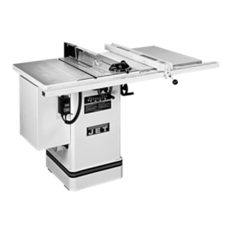
- Page 1 OWNER'S MANUAL JWCS-10A Cabinet Saw JWCS-10A-PF Shown JET EQUIPMENT & TOOLS, INC. P.O. BOX 1349 Phone:253-351-6000 A WMH Company Auburn, WA 98071-1349 Fax: 1-800-274-6840 www.jettools.com e-mail jet@jettools.com M-708435 12/00...
-
Page 2: Warranty
LIMITED TOOL AND EQUIPMENT WARRANTY JET makes every effort to assure that its products meet high quality and durability standards and warrants to the original retail consumer/purchaser of our products that each product be free from defects in materials and workmanship as follows: 2 YEAR LIMITED WARRANTY ON THIS JET PRODUCT. -
Page 3: Warnings
14. Keep visitors a safe distance from the work WARNING area. 1. Read and understand the entire 15. Use recommended accessories; improper instruction manual before attempting accessories may be hazardous. assembly or operation. 16. Never place hands directly in line with the 2. -
Page 4: Grounding Instructions
Grounding Instructions Caution: This tool must be grounded while in use to protect the operator from electric shock. In the event of a malfunction or breakdown, grounding provides a path of least resistance for electric current to reduce the risk of electric shock. This tool is equipped with an electric cord having an equipment-grounding conductor and a grounding plug. -
Page 5: 230V Operation
4. The 115V attachment plug (A), supplied with the tablesaw, must be replaced with a UL/CSA listed plug suitable for 230V operation (D). Contact your local Authorized JET Service Center or qualified electrician for proper procedures to install the plug. The tablesaw must comply with all local and national codes after the 230 volt plug is installed. -
Page 6: Table Of Contents
Shipping Weight (approx.) ......................317 lbs. The specifications in this manual are given as general information and are not binding. JET Equipment & Tools reserves the right to effect, at any timeand without prior notice, changes or alterations to parts, fittings, and accessory equipment... -
Page 7: Contents Of The Shipping Container
WARNING Read and understand the entire contents of this manual before attempting assembly or operation! Failure to comply may cause serious injury! Contents of the Shipping Container Saw w/ Cabinet Extension Wing Blade Guard Assembly Push Stick Arbor Wrench Miter Gauge Assembly Blade Guard Mounting Bracket Assembly Hardware Bag (blade guard assembly) Handle Assemblies... -
Page 8: Installation And Leveling
WARNING Do not connect the table saw to the power source until all assembly has been completed! Failure to comply may cause serious injury! Installation and Leveling Final location for the saw must be level, dry, well lighted, and have enough room to allow movement around the saw with long pieces of wood. -
Page 9: Hand Wheel Assembly
Hand Wheel Assembly Hardware: (2) Handles, (2) Hand Wheels & (2) Lock Knobs Tool: 14mm Wrench 1. Attach handle (A, Fig. 4) to hand wheel (B, Fig. 4). 2. Attach hand wheel assembly to saw with lock knob (C, Fig. 4). 3. -
Page 10: Blade Guard Assembly
Insert front tab of blade guard splitter 2. Using a straight edge (B, Fig. 8), align the through insert opening in table and onto hex splitter with the saw blade. Be sure that cap bolt (A, Fig.7). Hand tighten only at this straight edge rests against body of saw time. -
Page 11: Table Insert Adjustment
2. To tilt the saw blade, loosen lock knob, turn Table Insert Adjustment handwheel (C, Fig. 11) until desired angle is obtained, then tighten lock knob. Hardware: Table Insert Tools: 3mm Hex Wrench, Straight Edge 1. Lower blade completely. 2. Place the open end of the insert under the splitter and lower the insert into the opening. -
Page 12: Adjusting 45 And 90 Positive Stops
5. Tighten the lock nut and reset the pointer. WARNING When making adjustments always disconnect saw from the power source! Failure to comply may cause serious injury! Adjusting 45 and 90 Positive Stops Hardware: Square Tools: 3mm Hex Wrench, 10mm Wrench 1. -
Page 13: Wear Adjustment In Tilting Mechanism
3. Turn eccentric sleeve (B, Fig. 15) until play is removed. Flat area on sleeve accommodates a wrench. 4. Tighten lock nut. Electrical Connections The JWCS-10A table saw is rated at 115V/230V, prewired 115V. WARNING! All electrical connections must be done by a qualified electrician! -
Page 14: Troubleshooting
Troubleshooting Trouble Possible Cause Solution 1. Overload tripped on motor 1. Allow motor to cool and reset 2. Saw unplugged from wall or overload switch on motor motor 2. Check all plug connections Saw stops or will not start 3. Fuse blown or circuit breaker 3. -
Page 15: Cabinet & Table Assembly Parts Breakdown
Cabinet & Table Assembly... -
Page 16: Cabinet & Table Assembly Parts List
Parts List For The JWCS-10A Cabinet & Table Assembly Index Part Description Size Qty. 1..290001W ......Table....................1 2..708101......Table Insert ..................1 3..TS-1523031 ..... Set Screw............M6x10 ......4 4..290004W ......Extension Wing ................1 5..TS-1491041 ..... Hex Cap Bolt ..........M10x30 ....3 6..TS-1551071 ..... - Page 17 Index Part Description Size Qty. 52 ..990805......Self Tapping Screw ........M4x10 ......6 53 ..290122W ......Motor Cover ...................1 54 ..290124......Knob.............. M6 ......1 55 ..991002......Flange Nut............. M6 ......1 56 ..TS-1524051 ..... Set Screw............M8x20 ......2 57 ..708818......Push Stick ..................1 58 ..TS-1540061 .....
-
Page 18: Motor & Trunnion Assembly Parts Breakdown
Motor & Trunnion Assembly... -
Page 19: Motor & Trunnion Assembly Parts List
Parts List For The JWCS-10A Motor & Trunnion Assembly Index Part Description Size Qty. 1..200035......Eccentric ..................1 2..TS-231014-2 ....Hex Nut ............M14x1.5 ....1 3..TS-155110 ....... Lock Washer ..........M16 ......2 4..200052......Rear Trunnion Bracket..............1 5..TS-1490051 ..... Hex Cap Bolt ..........M8x30 ......2 6..TS-1551061 ..... - Page 20 Index Part Description Size Qty. 54 ..200102......Flange ....................1 55 ..991416......Nut ..............5/8”x12 .....1 56 ..BB620303 ......Bearing............6203LLU....2 57 ..991172......Nut ..............M16x1.5 ....4 58 ..290106......Arbor Pulley..................1 59 ..992068......Key..............5x5x40 .....1 60 ..TS-1523031 ..... Set Screw............M6x10 ......2 61 ..200109......