
Related Manuals for Jet JDP-20MF


Summary of Contents for Jet JDP-20MF
-
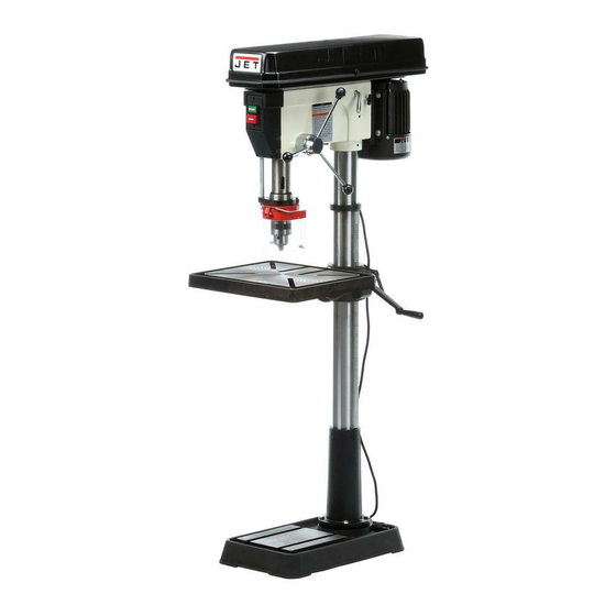
Page 1: Drill Press
Operating Instructions and Parts Manual Drill Press Model: JDP-20MF WMH TOOL GROUP 2420 Vantage Drive Elgin, Illinois 60123 Part No. M-354170 Ph.: 800-274-6848 Revision G 04/04 www.wmhtoolgroup.com Copyright © WMH Tool Group... -
Page 2: Warranty
This manual has been prepared for the owner and operators of a JDP-20MF Drill Press. Its purpose, aside from machine operation, is to promote safety through the use of accepted correct operating and maintenance procedures. Completely read the safety and maintenance instructions before operating or servicing the machine. -
Page 3: Table Of Contents
Parts List JDP-20MF ... 18 Wiring Diagram ... 21 JDP-20MF Electrical Schematic – 115V ... 21 JDP-20MF Electrical Schematic – 230V ... 21 The specifications in this manual are given as general information and are not binding. WMH Tool Group reserves the right to effect, at any time and without prior notice, changes or alterations to parts, fittings, and accessory equipment deemed necessary for any reason whatsoever. -
Page 4: Warnings
4. This drill press is designed and intended for use by properly trained and experienced personnel only. If you are not familiar with the proper and safe operation of a drill press, do not use until proper training and knowledge have been obtained. - Page 5 21. Keep visitors a safe distance from the work area. Keep children away. 22. Make your workshop child proof with padlocks, master switches or by removing starter keys. 23. Give your work undivided attention. Looking around, carrying on a conversation and “horse-play” are careless acts that can result in serious injury.
-
Page 6: Specifications
Specifications Model Number...JDP-20MF Stock Number ... 354170 Swing...20-1/2” Type ...Floor Drilling Capacity ... 1” Chuck Size ... 3/4” Spindle Travel ...4-5/8” Spindle Distance to Base ...46-3/4” Spindle Distance to Table (max.)...29-1/8” Table Size (Length x Width)... 18-1/2" x 16" Spindle Taper...MT-3 Column Diameter ...3-3/8”... -
Page 7: Shipping Contents
Shipping Contents Unpack the carton and verify that all parts listed below are included. Main Parts 1 ea Head Assembly 1 ea Table 1 set Column and Table Bracket Assembly 1 ea Base Additional Parts 1 set Chuck and Chuck Key 1 pc Arbor 1 pc... -
Page 8: Assembly
1. Remove the contents from the shipping container. 2. Compare contents container with the list on page 7. Report any shortages or damage to your JET distributor. 3. Clean rust protected kerosene or a light solvent. lacquer thinner, paint thinner, or gasoline. -
Page 9: Crank Handle
Crank Handle Referring to Figure 4: 1. Loosen the setscrew (B) on the table crank handle (A). 2. Slide the handle (A) onto the table bracket shaft. 3. Turn the handle until the setscrew is opposite the flat section on the shaft, and tighten the setscrew to secure the handle. -
Page 10: Head Assembly
Head Assembly Referring to Figure 7: 1. With the aid of a second person, carefully lift the head onto the column top and slide it down into position The head assembly is heavy! Use care when lifting onto the column! 2. -
Page 11: Chuck And Arbor Removal
Chuck and Arbor Removal Unplug machine from the power source. Raise the table until it is about seven inches below the chuck. Place a piece of scrap wood on the table, and lower quill (A, Fig. 9) using the downfeed handle. -
Page 12: Return Spring Adjustment
Return Spring Adjustment The return spring is adjusted at the factory and should not need further adjustment. If adjustment is deemed necessary, follow the steps below while referring to Figure 12: 1. Unplug the machine from the power source. 2. Loosen two hex nuts (A). Do not remove. Do not remove the coil spring cover (Step 3). -
Page 13: Operation
Using the Vise For the small workpiece that cannot be clamped to the table, use a drill press vise. The vise must be clamped or bolted to the table. Always use a back-up piece of scrap wood to cover the table. -
Page 14: Grounding Instructions
UL/CSA listed plug suitable for 230V operation (D). Contact your local Authorized JET Service Center or qualified electrician for proper procedures to install the plug. The drill press must comply with all local and national codes after the 230-volt plug is installed. -
Page 15: Troubleshooting
Troubleshooting Trouble Probable Cause Drill press unplugged from wall, or motor. Drill press will not Fuse blown, or circuit breaker tripped. start. Cord damaged. Starting capacitor bad. Extension cord too light or too long. Drill press does not come up to speed. -
Page 16: Replacement Parts
Troubleshooting (cont.) Trouble Probable Cause Bent drill bit. Excessive drill bit Worn spindle bearings. runout, or wobble. Bit, or chuck not properly installed. Quill returns too slow, Spring has improper tension. or too fast. Chuck or arbor does Dirt, grease, etc on arbor, chuck, or not stay in place. -
Page 17: Exploded View Drawing Jdp-20Mf
Exploded View Drawing JDP-20MF... -
Page 18: Parts List Jdp-20Mf
Parts List JDP-20MF Index No. Part No. Description Size 1 ...11300117 ...Base JDP-20MF..1 ...11400401A1...Column & Holder Assembly (Index 2A, 2B)... Ø85mm ... 1 2A ...JDP20-102A...Column..1 2B ...JDP20-102B...Holder..1 3 ...TS-1525021 ...Socket Set Screw... M10x12 ... 1 4 ...TS-1523041 ...Socket Set Screw... - Page 19 Index No. Part No. 64 ...11406403 ...Spindle Nut..1 65 ...11406508 ...Drive Sleeve..1 66 ...BB-6206Z...Ball Bearing... 6206Z... 2 67 ...11406706 ...Collar..1 68 ...11406803 ...Retaining Ring ..2 69 ...10606902 ...Pulley Set Nut ..1 70 ...11407019 ...Spindle Pulley ...
- Page 20 Index No. Part No. Description Size 618 ...10604505 ...Round Nut ..1 619 ...TS-0720091 ...Lock Washer ... 3/8”... 1 700 ...TS-152704 ...Hex Wrench ... 3mm ... 1 701 ...TS-152706 ...Hex Wrench ... 5mm ... 1 801 ...28065558B3...Bulb Wire..1 805 ...10280501 ...Bulb Sticker ...
-
Page 21: Wiring Diagram
Wiring Diagram JDP-20MF Electrical Schematic – 115V JDP-20MF Electrical Schematic – 230V ON / OFF SWITCH BLACK BLACK WHITE WHITE GREEN GREEN GROUND LAMP SWITCH BLACK BLACK WHITE BLACK ON / OFF SWITCH BLACK BLACK WHITE WHITE GREEN GREEN GROUND... - Page 22 NOTES...
- Page 23 NOTES...
- Page 24 WMH Tool Group 2420 Vantage Drive Elgin, Illinois 60123 Phone: 800-274-6848 www.wmhtoolgroup.com...