Advertisement
Quick Links
ALESIS
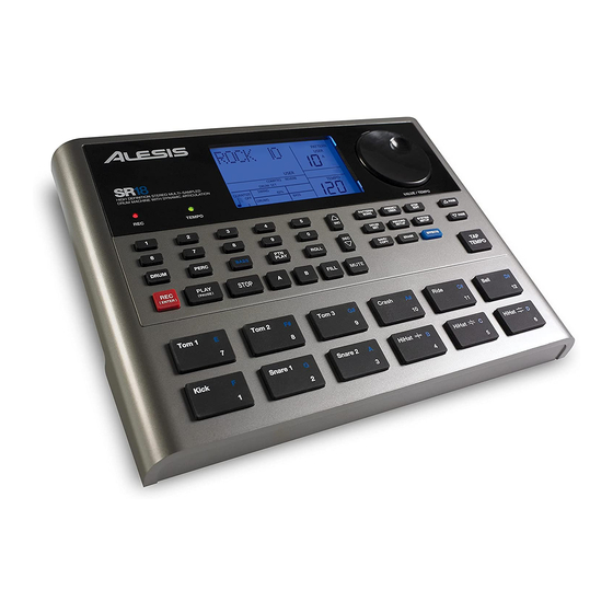
SR-18 (LD32)
Service Manual
P/N: 8-31-0183-A
ATTENTION!
THIS DOCUMENT CONTAINS SENSITIVE
PROPRIETARY INFORMATION.
ALL RECIPIENTS MUST HAVE A CURRENT
NON-DISCLOSURE AGREEMENT ON FILE
WITH ALESIS, LLC.
DO NOT MAKE ILLEGAL
COPIES OF THIS DOCUMENT
The information in this document contains privileged and confidential information.
It is intended only for the use of those authorized by Alesis. If you are not the
authorized, intended recipient, you are hereby notified that any review,
dissemination, distribution or duplication of this document is strictly prohibited. If
you are not authorized, please contact Alesis and destroy all copies of this
document. You may contact Alesis at servicemanuals@alesis.com or at
support@alesis.com.
Copyright Alesis, LLC
Confidential
Alesis Service Manual
8-31-0183-A
Advertisement

Related Manuals for Alesis SR-18


Summary of Contents for Alesis SR-18
- Page 1 COPIES OF THIS DOCUMENT The information in this document contains privileged and confidential information. It is intended only for the use of those authorized by Alesis. If you are not the authorized, intended recipient, you are hereby notified that any review, dissemination, distribution or duplication of this document is strictly prohibited.
- Page 2 Your purchase of the Manual shall be for your own ultimate use and shall not be for purposes of resale or other transfer. As the owner of the copyright to the Manual, Alesis does not give you the right to copy the Manual, and you agree not to copy the Manual without the written authorization of Alesis. Alesis has no obligation to provide to you any correction of, or supplement to, the Manual, or any new or superseding version thereof.
- Page 3 ALL REPAIRS DONE BY ANY ENTITY OTHER THAN AN AUTHORIZED ALESIS SERVICE CENTER SHALL BE SOLELY THE RESPONSIBILITY OF THAT ENTITY, AND ALESIS SHALL HAVE NO LIABILITY TO THAT ENTITY OR TO ANY OTHER PARTY FOR ANY REPAIRS BY THAT ENTITY.
-
Page 4: Safety Instructions
The product is exposed to water or excessive moisture, c. The AC power supply plug or cord is damaged, d. The product shows an inappropriate change in performance or does not operate normally, or e. The enclosure of the product has been damaged. Confidential Alesis Service Manual 8-31-0183-A... - Page 5 SERVICE MANUAL MODEL:LD32...
-
Page 6: Technical Specifications
SPECIFICATIONS TECHNICAL SPECIFICATIONS 1 TRS ¼” (aux) Audio Outputs: 2 TS ¼” (main) 1 TRS ¼” (phones) Pads: 12 velocity sensitive (w/Dynamic Articulation™) Sample/DAC Bit Resolution 16 / 24 Sounds: Sounds Accessible via Pads Sounds Accessible via MIDI Polyphony 32 voice Panning 7-position user programmable Velocity Response... -
Page 7: Disassembly Procedures
DISASSEMBLY PROCEDURES 1. DISASSEMBLE THE CABINET (Fig1) (A) REMOVE 4 SCREWS FROM THE BOTTOM PANEL. (B) REMOVE 2 PCS OF CABLE CONNECTOR FROM THE MAIN PCB. (Fig1) - Page 8 2. DISASSEMBLE THE FONCTION PCB ASS’Y. (Fig2) (A) REMOVE THE CABLE FROM LCM (B) REMOVE 16 SCREWS (Fig.2) 3.DISASSEMBLE THE ENCODER PCB ASS’Y. (Fig.3) REMOVE 1 SCREW (Fig.3)
- Page 9 4.DISASSEMBLE THE MAIN PCB ASS’Y. (Fig.4) (A) REMOVE 1 CABLE CONNECTOR (B) REMOVE 2 SCREWS (Fig.4)
- Page 13 Diagnostic Specification XR-20 and Alesis LD32 Product Code: ACD1/LD32 Document Version 0.90 Last Revised: 2008/01/01...
- Page 14 1. Memory Test Upon startup, holding down [PLAY] should run the memory test from boot code. The screen will indicate whether the test was successful or a failure. After this test, power down the unit to enter diagnostics mode. RAM Test Wait..
- Page 15 Diags When the test is executed, the LCD should show: All On All LEDs shall turn on. 5. Test 3: Switch Test The LCD should show display the following: Diags Switch When the test is executed, the LCD should show: SWITCH The user will then press the switches one at a time.
- Page 16 RecSet SysSet Copy Erase Once all switches are pressed the LCD will display: SWITCH Passed Pressing [STOP] will then bring the user to the test select page. Pressing [STOP] twice in a row during the test will abort the test, and the LCD will display: SWITCH Abort Pressing [STOP] will then bring the user to the test select page.
- Page 17 The user will then press the pads one at a time. When each pad is pressed, its number and the input velocity shall appear on the second line, such as: PADS 16v127 PADS 1 v001 Once all pads are pressed the LCD will display: PADS Passed Pressing [STOP] will then bring the user to the test select page.
- Page 18 Once all footswitches are pressed the LCD will display: FOOTSW Passed Pressing [STOP] will then bring the user to the test select page. Pressing [STOP] during the test will abort the test, and the LCD will display: FOOTSW Abort Pressing [STOP] will then bring the user to the test select page. If during the test more than one footswitch is detected at a time, the LCD should display: FOOTSW Failed...
- Page 19 In this test the unit should generate a 300 Hz tone and output on all the outputs. If [PAGE >] or [<PAGE] is pressed then the display should cycle through the following outputs in incrementing or decrementing order based on the button (PAGE> is increase and <PAGE will decrease).
- Page 20 FLASH Passed FLASH Failed 12. Test 10: Serial EEPROM Test The LCD should show display the following: Diags EEPROM Upon the user pressing [PLAY] the system will write/read a small reserved section of the EEPROM and verify the results: EEPROM Passed EEPROM Failed...
- Page 21 Audio Spec Test This procedure verifies the audio specifications for mass production.
- Page 23 ALESIS SR-18 (LD32) SCHEMATIC FILES Confidential Alesis Service Manual 8-31-0183-A...
- Page 67 ALESIS SR-18 (LD32) HISTORY Confidential Alesis Service Manual 8-31-0183-A...
- Page 70 CONFIDENTIAL!
- Page 71 ALESIS SR-18 (LD32) Confidential Alesis Service Manual 8-31-0183-A...
- Page 72 LD32ALE DESCRIPTION LEVEL PT1304702 PLATE BALE48201-5A LED FIXED 1.5MM TP022620T TAPE D26.5 X d20MM BA71028-130 BATTERY TERMINAL 71028-130 BA71209-130 BATTERY TERMINAL 71209-130 BA71228-130 BATTERY TERMINAL 71228-130 BAAR-142 RUBBER FEET BAAR-8.7X5 RUBBER GASKET EVA1304434 EVA 29x5x0.5mm EVA1304435 EVA 70x5x0.5mm EVA1304436 EVA 155x28x0.5mm K46-1 CABLE TIE LAC22ALE49...
- Page 73 AL9-79-0431 MAIN PCB ASSY AL0-09-0074 POTENTIOMETER ROTARY 10K 25A S AL0-15-0103 RESISTOR R16,25,59,75,76,107,110,112,116,158~164 AL0-15-0105 RESISTOR AL0-16-1151 RESISTOR 1.15K(SMD)1%0805 R3,128 AL0-16-3830 RESISTOR R123 AL0-16-8251 RESISTOR R26,52,55,86,87,92 AL1-08-0223 ELECT AL1-51-0475 C.CAP 150P/50V AL1-55-0470 CERMAIC 47PF NPO 50V 0805 C31,32,63,65 AL1-55-0561 CAP 560PF NPO 0805 C76,78 AL1-55-0751 CAP 750PF NPO 0805...
- Page 74 IC74AHC174 IC 74AHC174 SOP-16 IC74AUP1G32 IC 74AUP1G32 SOT23-5 IC74LVC14 IC 74LVC14 SOP-14 U5,16 IC74VHC27M IC 74VHC27M SOP-14 ICBF531 IC DSP ADSP-BF531 ICK4S641632E SDRAM IC ICLM317 IC LM317 1.5A SOT-223 ICM25PE80 IC 8Mbit , low-voltage,Page-Er ICMC34074A IC MC34074ADR2G SOIC-14 U6~8 ICMIC809SU RESET IC(2.93V) ICNJM2387 JKDJ-0702B-025...
- Page 75 FCN1R0503001 CONNECTOR LD-LTL-709E LIGUID-EMITTING DIODE RED SPOT LD-LTL-709L LIGUID-EMITTING DIODE GREEN SP RS000008J05 RES SMD 0 R1,6~13,16,17 RS027K08J05 RES SMD 27K RS18118J05 RES 180 (SMD) RS22218J05 RES 2.2K 5% SMD 0805 R3,18,19,20 RS68018J05 RES 68 (SMD) TE962003002 BOX HEADER STRAIGHT PITCH 2.0M TP022620T TAPE D26.5 X d20MM (X1~3)