Icom IC-M802 Instruction Manual
Mf/hf marine transceiver
Hide thumbs
Also See for IC-M802:
- Service manual (141 pages) ,
- Instruction manual (80 pages) ,
- Notes on operation (20 pages)
Table of Contents
Advertisement
Advertisement
Table of Contents

Related Manuals for Icom IC-M802


Summary of Contents for Icom IC-M802
- Page 1 INSTRUCTION MANUAL MF/HF MARINE TRANSCEIVER iM802...
-
Page 2: Foreword
We want to take a couple of moments of your time to thank you for making the IC-M802 your radio of choice, and hope you agree with Icom’s philosophy of “tech- nology first.” Many hours of research and develop- ment went into the design of your IC-M802. -
Page 3: Table Of Contents
IN CASE OF EMERGENCY When your ship requires assistance, contact other ships and the Coast Guard by sending a distress call using digital selective calling on 2187.5 kHz. When immediate help is needed q Push and hold [DISTRESS] for 5 sec. until the short beeps become one long beep, to send the distress call. -
Page 4: Quick Reference
QUICK REFERENCE I How to set a Channel/Group The IC-M802 has up to 160 user-programmable, 242 ITU SSB duplex, 72 ITU SSB simplex and 662 ITU FSK duplex channels. D D Using the group and channel selectors [GRP] [CH] D D Using the keypad Numeral keys •... -
Page 5: I Audio Output/Squelch Adjustment
I Audio output/squelch adjustment D D Audio output level ➥ Rotate [VOL] to adjust audio output level. NOTE: Make sure that no “ cators are displayed during audio level adjustment, otherwise, audio may not be output. When either or both indicators are displayed, per- form the following operations;... -
Page 6: I Basic Voice Transmission And Reception
QUICK REFERENCE I Basic voice transmission and reception D D Receiving a signal q Select the desired channel via [GRP] and [CH], or keypad. • Turn ON/OFF the squelch function or adjust the squelch level as desired. w When a signal is received, “ and audio is output from the connected speaker. -
Page 7: I Receiving A Dsc
I Receiving a DSC ➥ For waiting for a DSC call, such as an individual, group or all ships call on the desired frequencies, push [DSC] to enter DSC watching mode. • Monitoring the frequencies, 2187.5, 4207.5, 6312.0, 8414.5, 12577.0 and 16084.5 kHz, for distress, ur- gency, etc., no operation is necessary with the trans- ceiver. - Page 8 QUICK REFERENCE D D Regular distress call q Push [DSC] to enter DSC watch mode. [DSC] w Push [MODE ] to enter DSC menu. [MODE [CH] e Rotate [CH] to select “ [ENT] Ç r Rotate [CH] to select the desired nature then push [ENT].
-
Page 9: Operating Rules And Guidelines
OPERATING RULES AND GUIDELINES Before transmitting, monitor the channel you wish to use so as to avoid interrupting transmissions al- ready in progress. • CALL PROCEDURE Calls must be properly identified and the time limit must be respected. q Give your call sign each time you call another ship or coast guard station. -
Page 10: Panel Description
PANEL DESCRIPTION I Front panel— Controller DISTRESS q DISTRESS SWITCH [DISTRESS] (p. 18) Push for 5 sec. (approx.) to make a distress call. w DSC SWITCH [DSC] Switches DSC watch mode and voice/e-mail com- munication mode when pushed. e CANCEL/CALL SWITCH [CANCEL/CALL] ➥... - Page 11 !2 FREQUENCY/CHANNEL SWITCH [FREQ/CH] ➥ Selects indication type: (p. 8) When channel comment indication is ON; switches channel comment indication ON and OFF. When channel comment indication is OFF; switches transmit frequency indication ON and OFF. ➥ After pushing [F], enters channel name pro- gramming mode, when channel comment indica- tion is ON.
-
Page 12: I Front Panel- Main Unit
PANEL DESCRIPTION I Front panel— Main unit q GPS CONNECTOR [GPS] (pgs. 53, 62) Input position and UTC data (NMEA0183 ver. 3.01 format), such as from a GPS receiver, etc., for set- ting your positioning and time data automatically without manual input for DSC operation. w REMOTE CONNECTOR [REMOTE] (pgs. -
Page 13: I Rear Panel- Main Unit
I Rear panel— Main unit q TUNER CONTROL SOCKET (pgs. 54, 56, 61) Connects a control cable to an optional antenna tuner. A female connector kit is supplied for external an- tenna tuner connection. w GROUND TERMINAL IMPORTANT! Connects a ship’s (or vehicle’s) ground. -
Page 14: I Lcd Screen
PANEL DESCRIPTION I LCD screen The IC-M802 has 2 indication types, one is channel name indication and the other is frequency indication. These indication types can be switched with a push of a button, depending on set mode’s setting. See pages 8 and 50 for display type settings. - Page 15 q RECEIVE INDICATOR “ ” appears when signals are received or the squelch is open. w TUNE INDICATOR “ ” blinks while tuning, if an optional external antenna tuner is connected. (p. 10) • “ ” appears after tuning is completed with AT-140, AT-130/E and AH-3.
-
Page 16: Setting A Channel
SELECTING A CHANNEL/FREQUENCY I Selecting a channel The transceiver has 160 user channels and ITU chan- nels. However, the number of user channels can be optionally restricted. D D Display selection FREQUENCY indication NOTE: Channel name (alphanumeric) may not ap- pear during frequency indication depending on ini- tial set mode setting. - Page 17 D D Using the keypad Direct channel selection via the keypad is available for quick channel selection. q Enter the desired channel number via the keypad. • Pushing [CE] clears input digits and retrieves the chan- nel. • A user channel is selected when channel 1–160 is input (max.
-
Page 18: Receive And Transmit
RECEIVE AND TRANSMIT I Basic voice transmit and receive q Check the following in advance. ➥ Microphone is connected. ➥ No “ ” indication. • If “ ” appears, push [F] then [2 squelch OFF. ➥ No “ ” indication. •... -
Page 19: I Functions For Receive
I Functions for receive D D Squelch function The squelch function detects signals with voice com- ponents and squelches (mutes) unwanted signals such as unmodulated beat signals. This provides quiet stand-by. When you need to receive weak signals, the squelch should be turned OFF. -
Page 20: I Cw Operation
• Adjustable between ±150 Hz in 10 Hz steps. D D Tuner through function In the combination with IC-M802 and optional AT-140 (or AH-3), the tuner through function can be used. By bypassing the tuner unit, the receiver gain in par- ticular frequency band may be improved depending on your antenna element length. -
Page 21: I Fsk Operation
➥ FSK tone, shift frequency and FSK polarity can be adjusted in initial set mode (p. 51) ➥ Some transceivers may operate 1.7 kHz higher than the IC-M802’s J2B mode even when the same displayed frequencies are in use. RECEIVE AND TRANSMIT... -
Page 22: Channel Name Programming
CHANNEL NAME PROGRAMMING Up to 8-character channel names can be assigned for each user and ITU channel. This may be helpful for in- dicating the frequency usage, ship name, etc. D Programming q Select the desired channel to be programmed. w Push [FREQ/CH] to select channel indication mode, if desired. -
Page 23: Dsc Preparation
I MMSI code programming The 9-digit MMSI (Maritime Mobile Service Identity: DSC self ID) code can be programmed. D D Programming [DSC] [MODE [CH] q While pushing [F] and [DSC], push [POWER] to turn the power ON. w Push [DSC] to select DSC watch mode. e Push [MODE •... -
Page 24: I Position And Time Programming
DSC PREPARATION I Position and time programming When no position and the UTC (Universal Time Coor- dinated) time data in NMEA0183 ver. 3.01 format, such as from a GPS receiver, etc., is applied to [GPS] con- nector, your position and the UTC time should be input for DSC operation. -
Page 25: Call Procedure
I Distress call A distress call should be transmitted if in the opinion of the Master, the ship or person is in distress and re- quires immediate assistance. A distress call should include the ship’s position and time. They are included automatically when their data in NMEA0183 ver. - Page 26 CALL PROCEDURE D D Simple distress call NOTE: • Distress alert (simple operation) contains (default); Distress nature : Undesignated distress. Position data : According to the displayed infor- mation. • Distress call repeats every 3.5–4.5 min., until re- ceiving an acknowledgement. •...
- Page 27 D D Regular distress call Transmit a distress call after selecting “ in the DSC menu. q Push [DSC] to select DSC watch mode. w Push [MODE set] to select the DSC menu. [DSC] [MODE [CANCEL/CALL] [CH] e Rotate [CH] to select “ [ENT].
- Page 28 CALL PROCEDURE D D When no acknowledgement is received If no acknowledgement is received, the emergency alarm will sound continuously. In this case, the IC- M802 automatically transmits the distress call again every 3.5 to 4.5 minutes. • Push [CANCEL/CALL] if you want to stop the alarm. •...
-
Page 29: I Distress Call To Ships
I Distress call to ships General DSC call with the “distress” category may be used for communications after the Distress call, e.g. you want to change the operating mode, frequency, etc. The call is transmitted one time only although the dis- tress call using the [DISTRESS] switch sends 5 times repeatedly. - Page 30 CALL PROCEDURE D D Operation for distress call to ships q Push [DSC] to select DSC watch mode. w Push [MODE ] to select the DSC menu. [DSC] [MODE [CANCEL/CALL] [CH] e Rotate [CH] to select “ [ENT]. r Rotate [CH] to select “ [ENT].
- Page 31 CALL PROCEDURE ✔ CONVENIENT! The IC-M802 has DSC TX memory. You can store often used DSC calling conditions for quick and sim- ple re-call. Up to 10 conditions can be stored into the memory with the following instructions.
-
Page 32: I Urgency Call
CALL PROCEDURE I Urgency call When you want to send an urgency message, such as medical transport announcement, etc., to other ships, use “Urgency” as the category. An urgency call is sometimes called a “PAN PAN call.” D Operation outline DSC menu Ç... - Page 33 D D Urgency call operation q Push [MODE ] to select the DSC menu. w Rotate [CH] to select either “ “ ” then push [ENT]. • When selecting “ ” e Rotate [CH] to select “ [ENT]. Ç r Rotate [CH] to select a traffic frequency from one of the pre-programmed frequencies or “...
- Page 34 CALL PROCEDURE • When selecting “ e Select “ ” as the category using [CH], then push [ENT]. Ç r Select (or enter) the 9-digit ID code, then push [ENT]. • Use [CH] to select the ID code when the desired ship’s ID is pre-programmed.
- Page 35 !1 When receiving an acknowledgement, the display shows the received ID code, or the called station name. • Push [FREQ/CH]; - to select the traffic frequency if the called station is able to comply to the call. - to return to DSC watch mode when unable. When the called station is unable to comply to the call, the reason may be displayed.
-
Page 36: I Safety Call
CALL PROCEDURE I Safety call When you want to send a safety message to other ships, use “Safety” as the category. A safety call is sometimes called a “SECURITE call.” D Operation outline DSC menu Ç Address ID selection Ç Traffic frequency selection 1 Ç... - Page 37 D D Safety call operation A safety call procedure is almost the same as the ur- gency call. q Push [MODE ] to select the DSC menu. w Rotate [CH] to select the desired DSC format from “ ” and “ [ENT].
- Page 38 CALL PROCEDURE • When selecting ‘ e Select “ ” as the category using [CH], then push [ENT]. Ç r Select the desired 9-digit ID code, then push [ENT]. • Use [CH] to select the ID code when the desired ship’s ID is pre-programmed.
- Page 39 !1 When receiving an acknowledgement, the display shows the received ID code, or the called station name. • Push [FREQ/CH]; - to select the traffic frequency if the called station is able to comply to the call. - to return to DSC watch mode when unable. When the called station is unable to comply to the call, the reason may be displayed.
-
Page 40: I Routine Call
CALL PROCEDURE I Routine call When you use DSC for general selective calling, use “Routine” as the category. q Push [MODE ] to select the DSC menu. w Rotate [CH] to select “ [ENT]. e Select “ ” as the category using [CH], then push [ENT]. - Page 41 !0 The calling stand-by screen is displayed as fol- lows, verify the calling condition then push and hold [CANCEL/CALL] for 1 sec. to transmit the rou- tine call. • Push and hold [ENT] for 1 sec. to store the calling con- dition into the TX memory described in pages 23 and 43, if desired.
-
Page 42: I Group Call
CALL PROCEDURE I Group call When you use DSC for calling the desired ship’s group, use “Group” menu. q Push [MODE ] to select the DSC menu. w Rotate [CH] to select “ e Select the desired 9-digit group code, then push [ENT]. -
Page 43: I Position Request Call
I Position request call The position request call is used to confirm the speci- fied ship’s position. This calling system uses digital sig- nals only, therefore a voice reply is not necessary. q Push [MODE ] to select the DSC menu. w Rotate [CH] to select the “... -
Page 44: I Test Call
CALL PROCEDURE I Test call Testing on the exclusive DSC distress and safety call- ing frequencies (such as 2187.5 kHz) should be avoided as much as possible by using other methods. When testing on the distress/safety frequency is un- avoidable, it should be indicated that these are test transmissions. -
Page 45: When Receiving A Call
I To receive a DSC call The independent built-in DSC receiver circuit in the IC- M802 scans all distress/safety frequencies, therefore, the “distress,” “urgency” and “safety” calls on those fre- quencies can be decoded at all times. D D When receiving a DSC call One of the following actions should be performed when a DSC call is received depending on the re- ceived DSC format (or category):... -
Page 46: I Received Information
WHEN RECEIVING A CALL I Received information When receiving a DSC call, the received format spec- ifier and its contents are memorized into the RX mem- ory. Distress calls (including other calls with a distress category) are stored separately from other calls. Up to 20 distress and up to 10 other categories of call can be memorized. -
Page 47: I Distress Call
I Distress call q When receiving a distress call, an emergency alarm sounds and the display below appears. w Push [CANCEL/CALL] to stop the alarm, if desired. • One distress call sequence is sent 5 times repeatedly within approx. 30 sec. The emergency alarm sounds at each reception. -
Page 48: I All Ships Call
Calling station’s name appear when the same ID is preprogrammed. I Geographical area call NOTE: The IC-M802 will not function for the geo- graphical call when: • Your position is out of the specified area. • GPS data is not connected to [GPS] and you haven’t input the position information manually. -
Page 49: I Individual Call
I Individual call When receiving an Individual call, beeps may sound (or the emergency alarm depending on the category) and the display below appears. Calling station’s name appears when the same ID is preprogrammed. You must send back an acknowledgement to the call- ing station in such cases. -
Page 50: I Position Request Call
WHEN RECEIVING A CALL I Position request call q When “ push [ENT]. Calling station’s name appears when the same ID is preprogrammed. w Push [ENT] to display the call contents for ac- knowledgement preparation. e Verify your position and time, then push [ENT]. ”... -
Page 51: Memory Operation
I Memory description The IC-M802 has several kinds of memories as fol- lows: • Address and group ID code memories (p. 44) • Call, traffic and scan frequency memories. (p. 45) • DSC transmission memory (described in this section) • Received message memory (p. 38) -
Page 52: Dsc Menu Operation
DSC MENU OPERATION I General Up to 100 ID codes with frequency and name can be programmed in MENU mode for easy recall during DSC call setting. I ID input A total of 100 ID codes can be programmed as “Ad- dress ID”... -
Page 53: I Frequency Input
I Frequency input A total of 50 frequency pairs can be programmed as “Call frequency,” “Traffic frequency” or “Scan fre- quency.” The frequency usage and frequency name are also programmed together with the frequency. D D SETTING PROCEDURES: q During DSC menu indication, rotate [CH] to select “... -
Page 54: I Verifying Self-Id
DSC MENU OPERATION I Verifying self-ID ➥ During setup select menu indication, rotate [CH] to select “ ” then push [ENT] to dis- play the programmed MMSI ID (self-ID). ➥ Push [DSC] to select DSC watch mode. ➥ Push [MODE ] to select DSC menu. -
Page 55: Mail Operation
I General The IC-M802 is ready for HF e-mail operation— up to 160 e-mail frequency channels and a connecting ter- minal for an e-mail modem are available. Independent e-mail frequencies with operating mode and filter settings can be selected with a push of a but- ton or group/channel selector rotation for simple oper- ation. -
Page 56: Set Mode
SET MODE I Quick set mode D D Entering quick set mode q Push [F] then [MODE ] to enter quick set mode. • Select voice or e-mail operation mode in advance. w Rotate [GRP] to select the desired item. e Rotate [CH] to set the values or conditions for the selected item. -
Page 57: I Initial Set Mode
FSK from ON and OFF. This item will not appear when ITU channels are in- hibited. External antenna tuner type This item selects the connected Icom antenna tuner type from AT-140, AT-130/E, AT-120/E and AH-3 • : AT-140 is connected. (default) •... - Page 58 SET MODE D D Initial set mode items (continued) Scan type This item selects one of the following scan functions. Programmed scan searches signals within the fre- quency range and activates slowly while squelch is open and fast while squelch is closed. Channel scan and channel resume scan searches 20 channels around a user selected channel, or searches all ITU channels in the band when an ITU...
- Page 59 D D Initial set mode items (continued) FSK shift frequency Several shift frequencies are used for FSK operation. This item selects an FSK shift frequency for almost any FSK system from 850 Hz, 425 Hz, 200 Hz and 170 Hz. FSK polarity Normal and reverse polarities are available for FSK operations.
- Page 60 SET MODE D D Initial set mode items (continued) REMOTE ID This item selects the ID for the transceiver from 1 to REMOTE connector interface This item selects the interface format for [REMOTE] connector. Modulation input/output selection This item selects the input/output terminal for signals to/from an external unit, such as an HF e-mail modem, TNC (Terminal Node Controller), etc.
-
Page 61: Connection And Installation
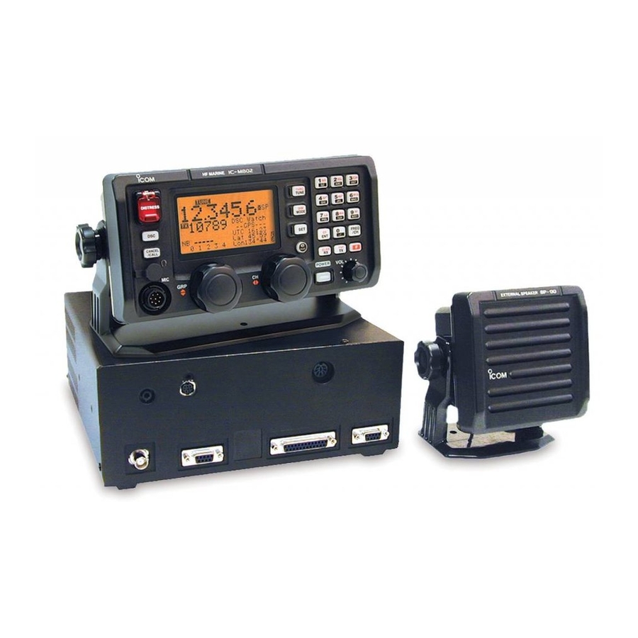
CONNECTION AND INSTALLATION I Supplied accessories The following accessories are supplied with IC-M802. q Microphone (HM-135) …………………………… 1 w External speaker (SP-24) ………………………… 1 e Mounting bracket kit for main unit …………… 1 set r Mounting bracket kit for remote controller (MB-81) ……………………………………………………... -
Page 62: I Rear Panel Connections
To prevent an accidental cable disconnection, partic- ularly for the external speaker and remote control ca- bles, the supplied cable tie may be helpful. q Install the cable tie (base) onto the IC-M802 main unit side panel, or desired place near the main unit. Grounding (see pgs. -
Page 63: I Ground Connection
I Ground connection The transceiver and antenna tuner MUST have an adequate RF ground connection. Otherwise, the over- all efficiency of the transceiver and antenna tuner in- stallation will be reduced. Electrolysis, electrical shocks and interference from other equipment could also occur. -
Page 64: I Antenna
See page 61 for pin assignment. D D Non-Icom tuner Some non-Icom tuners may be used with the IC- M802. Please consult your dealer if you wish to con- nect one. With a 50 Ω matched antenna all marine bands can- not be used. -
Page 65: I Mounting
I Mounting D Mounting location Select a location that provides easy access to the con- troller for navigation safety, has good ventilation and is not subject to sea spray. The controller should be at 90 degrees to your line of sight when operating it. D D Mounting the controller/speaker/main unit CONFECTION AND INSTALLATION CAUTION: KEEP the transceiver and microphone... -
Page 66: I Using The Optional Mb-75
CONFECTION AND INSTALLATION I Using the optional MB-75 The optional MB-75 flush mount is available for mount- ing the controller and speaker to a flat surface such as an instrument panel. q Using the template on the page 67 for the remote controller (RC-25), and page 69 for the speaker (SP-24), carefully cut a hole into the instrument panel (or wherever you plan to mount the controller... -
Page 67: I Transceiver Dimensions
CONFECTION AND INSTALLATION I Transceiver dimensions... -
Page 68: I Fuse Replacement
CONFECTION AND INSTALLATION I Fuse replacement The transceiver has 2 fuses (2 types) to protect inter- nal circuitry, 1 fuse for the fuse holder on the DC power cable and 1 for inside. If the transceiver stops func- tioning, check the fuses below. •... -
Page 69: I Connector Information
I Connector information Pin Pin name AF GND SEND 13.6 V DC GND MICROPHONE Pin Pin name MIC+ MIC– AF– TUNER Pin Pin name START 13.6V DC 13.6V Pin Pin name 1–3 4–6 CONFECTION AND INSTALLATION Description CW and FSK keying input. Ground line for AF signal. - Page 70 CONFECTION AND INSTALLATION I Connector information (continued) AF/MOD Pin Pin name MOD+ MOD– NAF+ NAF– SEND REMOTE Pin Pin name NMEA-OUT NMEA0183 ver. 3.01 data output. (“NMEA” selection for REMOTE IF. (p. 52)) NMEA-IN NMEA0183 ver. 3.01 data input. (“NMEA” selection for REMOTE IF. (p. 52)) Pin Pin name NMEA + NMEA _...
-
Page 71: Antenna And Grounding Considerations
GTO-15 wire interconnects the whip to the automatic tuner. The tuner is fed with coax (RG 213) and a control line from the back of the Icom SSB wherever you plan to hide the auto-tuner. Remember, the ICOM automatic tuner is fully au-... - Page 72 ANTENNA AND GROUNDING CONSIDERATIONS everything of ground potential. If you can get at your keel bolt, or tap a screw into the keel, your grounding is done. Lead incapsulated keels are the ultimate in grounds, and you may need nothing further. In powerboats, since there's no keel, you’re going to need to come up with at least 100 square feet of RF ground surface below the water line.
- Page 73 Loran whip. These tuner ground circuits are mandatory for any type of reliable operation. If you try to run an ICOM side- band set with a remote tuner that is undergrounded, you stand the chance of not only burning up your equipment, but also damaging other electronics onboard with stray RF.
-
Page 74: Specifications
SPECIFICATIONS • General • Frequency coverage Receive 0.5–29.9999 Transmit 1.6–2.9999 6.0–6.9999 12.0–13.9999 18.0–19.9999 25.0–27.5000 • DSC channels : 2,187.5 kHz, 4,207.5 kHz, 6,312.0 kHz, 8,414.5 kHz, 12,577.0 kHz, 16,804.5 kHz • Type of emission Transceiver (USB/LSB) (FSK) DSC receiver • No. of memory Ch. : 1136 channels (max.) 160 user programmable, 242 ITU SSB duplex, 72 ITU SSB simplex,... -
Page 75: Template
TEMPLATE I Remote controller (RC-25) ″ 92 mm; 3 ⁄ 4–R11... -
Page 76: I Speaker (Sp-24)
TEMPLATE I Speaker (SP-24) ″ 92 mm; 3 ⁄ 4–R11... -
Page 77: Options
Same as that supplied remote with the transceiver. Mounting bracket, MB-81, is supplied with the controller. HM-135 HAND MICROPHONE Same as supplied with the IC-M802. AT-140 AUTOMATIC ANTENNA TUNER Antenna and control cable receptacles for easy installation and tuner through function are available. - Page 78 A-6154H-1US-q Printed in Japan © 2002 Icom Inc. Icom America Inc. Icom (Europe) GmbH <Corporate Headquarters> Communication Equipment 2380 116th Avenue N.E., Bellevue, WA 98004, U.S.A. Himmelgeister Str. 100, Phone: (425) 454-8155 Fax: (425) 454-7619 D-40255 Düsseldorf, Germany URL: http//www.icomamerica.com Phone: 0211 346047 URL: http//www.icomeurope.com...