Icom IC-M802 Instruction Manual
Mf/hf marine transceiver
Hide thumbs
Also See for IC-M802:
- Service manual (141 pages) ,
- Instruction manual (78 pages) ,
- Notes on operation (20 pages)
Table of Contents
Advertisement
Quick Links
Advertisement
Table of Contents

Related Manuals for Icom IC-M802


Summary of Contents for Icom IC-M802
- Page 1 INSTRUCTION MANUAL MF/HF MARINE TRANSCEIVER iM802...
-
Page 2: Foreword
We want to take a couple of moments of your time to structions for the IC-M802. thank you for making the IC-M802 your radio of choice, and hope you agree with Icom’s philosophy of “tech- EXPLICIT DEFINITIONS nology first.”... -
Page 3: Table Of Contents
IN CASE OF EMERGENCY When your ship requires assistance, contact other ships and the Coast Guard by sending a distress call using digi- tal selective calling on an emergency frequency. When immediate help is needed When potential problems exist q Hold down [DISTRESS] for 5 seconds until the q Push [DSC] to select DSC watch mode, if neces- short beeps become one long beep, to send the sary. -
Page 4: Quick Reference
QUICK REFERENCE ■ How to set a Channel/Group The IC-M802 has up to 160 user-programmable, 249 ITU SSB duplex, 124 ITU SSB simplex and 662 ITU FSK duplex channels. D Using the group and channel selectors q Rotate [GRP] to select a desired group. -
Page 5: Audio Output/Squelch Adjustment
QUICK REFERENCE ■ Audio output/squelch adjustment D Audio output level × ➥ Rotate [VOL] to adjust audio output level. NOTE: Make sure that no “ ” and “SQL” indica- tors are displayed during audio level adjustment, otherwise, audio may not be output. If either or both indicators are displayed, perform the following operations;... -
Page 6: Basic Voice Transmission And Reception
QUICK REFERENCE ■ Basic voice transmission and reception D Receiving a signal • RF gain level q Select the desired channel using [GRP] and [CH], or the keypad. Push [F], [6 ] to enter the RF gain adjust- rf-g • Turn the squelch function ON and OFF, or adjust the ment mode, then rotate [CH] to adjust the gain. -
Page 7: Receiving A Dsc
QUICK REFERENCE ■ Receiving a DSC ➥ To receive a DSC call, such as an individual, group or all ships call on the desired frequencies, push [DSC] to enter the DSC watch mode. • Monitoring the frequencies, 2187.5, 4207.5, 6312.0, 8414.5, 12577.0 and 16804.5 kHz, for distress, ur- gency, etc., no operation is necessary with the trans- ceiver. - Page 8 QUICK REFERENCE D Regular distress call t Verify your position and the UTC time, then push q Push [DSC] to enter DSC watch mode. [ENT]. • When no position data from a GPS receiver is sent, your position and UTC time should be input in this step.
-
Page 9: Operating Rules And Guidelines
OPERATING RULES AND GUIDELINES Before transmitting, monitor the channel you wish to use to avoid interrupting transmissions already in progress. • CALL PROCEDURE • LOGS Calls must be properly identified and the time limit q All distress, emergency and safety calls must be must be respected. -
Page 10: Panel Description
PANEL DESCRIPTION ■ Front panel— Controller Function display (pp. 6, 7) DISTRESS i RX/CLARITY SWITCH [RX q DISTRESS SWITCH [DISTRESS] (p. 17) clar ➥ After pushing [F], turns the clarity function ON Hold down for 5 seconds (approximately) to make a or OFF. - Page 11 PANEL DESCRIPTION !2 FREQUENCY/CHANNEL SWITCH [FREQ/CH] ➥ Inputs the number “8” for channel num- ber input. ➥ Selects display type: (p. 8) ➥ Inputs “8,” “T,” “U,” “V,” “t,” “u” or “v” for When "CH-FREQUENCY" is selected; channel comment input. Toggles channel number and TX frequency.
-
Page 12: Front Panel- Main Unit
PANEL DESCRIPTION ■ Front panel— Main unit r ACCESSORY CONNECTOR [ACC] q GPS CONNECTOR [GPS] (pp. 55, 64) (pp. 13, 63) Input position and UTC data from a GPS receiver Connects a CW keyer or an FSK terminal unit. for DSC operation. (NMEA0183 ver. 3.01 format) •... -
Page 13: Rear Panel- Main Unit
PANEL DESCRIPTION ■ Rear panel— Main unit q TUNER CONTROL SOCKET (pp. 56, 58, 63) r ANTENNA CONNECTOR 2 (pp. 56, 58) Connects a control cable to an optional antenna Connects a 50 Ω HF band antenna through a 50 Ω tuner. -
Page 14: Lcd Screen
PANEL DESCRIPTION ■ LCD screen The IC-M802 has 3 display types; the channel name display, the frequency display and the DSC watch mode display. These indication types can be switched with a push of a button, depending on set mode’s set- ting. -
Page 15: Panel Description
PANEL DESCRIPTION q RECEIVE INDICATOR !1 CHANNEL NUMBER INDICATION “RX” is displayed when signals are received or the Displays the selected channel number. squelch is open. !2 S/RF INDICATOR w TUNE INDICATOR Displays the relative transmit output power levels “TUNE” blinks while tuning, if an optional external during transmit and the receive signal strength dur- antenna tuner is connected. -
Page 16: Setting A Channel/Frequency
SELECTING A CHANNEL/FREQUENCY ■ Selecting a channel The transceiver has 160 user channels and ITU chan- nels. However, the number of user channels can be optionally restricted. D Display selection FREQUENCY display CHANNEL display U S B S I M P U S B S I M P C H - - - G P S - - -... - Page 17 SELECTING A CHANNEL/FREQUENCY D Using the keypad [EXAMPLE]: Selecting channel 158 The keypad can be used to directly enter channels. U S B q Enter the desired channel number using the key- pad. • Pushing [CE] clears the input digits and returns to the C H - - - G P S - - - previous channel.
-
Page 18: Receive And Transmit
RECEIVE AND TRANSMIT ■ Basic voice transmit and receive q First, check the following. w Rotate [GRP] and [CH] to select the desired chan- ➥ Microphone is connected. nel to receive. ➥ “SQL” is not displayed. • When receiving a signal, the S-meter shows the signal strength. -
Page 19: Functions For Receive
RECEIVE AND TRANSMIT ■ Functions for receive D Squelch function The squelch function detects signals with voice com- ponents and squelches (mutes) unwanted signals such as unmodulated beat signals. This provides quiet stand-by. When you need to receive weak signals, turn OFF the squelch. -
Page 20: Receive And Transmit
• Adjustable between ±150 Hz in 10 Hz steps. D Tuner through function In the combination with IC-M802 and optional AT-140 (or AH-3), the Tuner Through function can be used. By bypassing the tuner unit, the receiver gain in a particular frequency band may be improved, depend- ing on your antenna element length. -
Page 21: Cw Operation
➥ FSK tone, shift frequency and FSK polarity can AF input be adjusted in the initial set mode. (p. 53) ➥ Some transceivers may operate 1.7 kHz higher than the IC-M802’s J2B mode, even when the same displayed frequencies are is selected. -
Page 22: Channel Name Programming
CHANNEL NAME PROGRAMMING Channel names of up to 8 characters can be assigned NOTE: The display type must be set to “CH-NAME” to each user and ITU channel. This may be helpful to to display/program the channel names in the initial indicate the frequency used, ship name, and so on. -
Page 23: Dsc Preparation
DSC PREPARATION ■ MMSI code programming When no 9 digit MMSI (Maritime Mobile Service Iden- tity DSC self ID) code has been programmed, follow the instructions below. NOTE: The programming can only be done once. If You cannot program the MMSI code if it has already you make a mistake, you must take the transceiver been programmed. -
Page 24: Position And Time Programming
DSC PREPARATION ■ Position and time programming When no GPS receiver is connected to the [GPS] con- IMPORTANT! nector, the position and the UTC time should be manu- The manually programmed position and the UTC ally input for the DSC operation. time settings will be cleared once the power is turned OFF. -
Page 25: Call Procedure
CALL PROCEDURE ■ Distress Call NEVER USE THE DISTRESS CALL WHEN YOUR A distress call should be transmitted, if in the opinion SHIP OR A PERSON IS NOT IN AN EMERGENCY. of the Master, the ship or a person is in distress and DISTRESS CALLS CAN BE USED ONLY WHEN requires immediate assistance. - Page 26 CALL PROCEDURE D Simple distress call NOTE: • Hold down [DISTRESS] for 5 seconds to transmit • Distress alert simple operation defaults are: a renewed distress call, if desired. Distress nature : Undesignated distress. • Push [CANCEL/CALL] to cancel the call repeat Position data : According to the displayed infor- mode.
- Page 27 CALL PROCEDURE D Regular distress call NEVER USE THE DISTRESS CALL WHEN YOUR Transmit a distress call after selecting “Distress” in the DSC menu. SHIP OR A PERSON IS NOT IN AN EMERGENCY. DISTRESS CALLS CAN BE USED ONLY WHEN IMMEDIATE HELP IS NEEDED.
- Page 28 CALL PROCEDURE D When no acknowledgement is received D After receiving an acknowledgement call If no acknowledgement is received, the IC-M802 auto- Speak into the microphone and give the following in- matically transmits the distress call again every 3.5 to formation after receiving a distress acknowledgement 4.5 minutes.
-
Page 29: Distress Call To Ships
CALL PROCEDURE ■ Distress call to ships General DSC calls with the “distress” category may be sent after the Distress call. For example, you want to change the operating frequency, and so on. The call is transmitted one time only although the dis- tress call using the [DISTRESS] switch is repeated 5 times. - Page 30 CALL PROCEDURE D Distress call to ships q Push [DSC] to select the DSC watch mode. u Rotate [CH] to select the desired preprogrammed w Push [MODE ] to select the DSC menu. traffic frequency, or “Manual set” then push [ENT].
- Page 31 CALL PROCEDURE ✔ CONVENIENT! !2 When receiving the acknowledgement call, the The IC-M802 has DSC TX memory. You can store display shows the received ID code, or the calling often used DSC calls for quick and simple re-call. Up station name.
-
Page 32: Urgency Call
CALL PROCEDURE ■ Urgency call When you want to send an urgency message, such as medical transport announcement, or other urgent situ- ation, to other ships, use “Urgency” as the category. An urgency call is sometimes called a “PAN PAN call.” D Operation outline DSC menu Category selection... - Page 33 CALL PROCEDURE D Urgency call operation q Push [MODE ] to select the DSC menu. w Rotate [CH] to select either “Individual” or “Geographical” then push [ENT]. • When selecting “ Geographical” e Rotate [CH] to select “Urgency,” then push u Enter the desired traffic frequencies for both the [ENT].
- Page 34 CALL PROCEDURE • When selecting “Individual” e Select “Urgency” as the category using [CH], u Rotate [CH] to select the desired calling frequency, then push [ENT]. then push [ENT]. * * * * * * I n d i v i d u a l * * * * * * * * * * * * I n d i v i d u a l * * * * * * - - - - - - - C a t e g o r y - - - - - - - - - - - C a l l f r e q u e n c y - - - -...
- Page 35 CALL PROCEDURE !0 When receiving an acknowledgement, the display shows the received ID code, or the called station name. • Push [FREQ/CH]; - to select the traffic frequency if the called station is able to comply to the call. - to return to DSC watch mode when unable. * * * * * * * * * * * * * * * * * * * * * * * * I n d i v i d u a l A C K I C - M 8 0 2...
-
Page 36: Safety Call
CALL PROCEDURE ■ Safety call When you want to send a safety message to other ships, use “Safety” as the category. A safety call is sometimes called a “SECURITE call.” D Operation outline DSC menu Category selection Category selection * * * * * * * D S C M E N U * * * * * * * * * * * * * I n d i v i d u a l * * * * * * * * * * * G e o g r a p h i c a l * * * * * - - - - - - - - S e l e c t - - - - - - - -... - Page 37 CALL PROCEDURE D Safety call operation q Push [MODE ] to select the DSC menu. w Rotate [CH] to select either “Individual” or “Geographical,” then push [ENT]. • When selecting “Geographical” e Rotate [CH] to select “Safety,” then push u Enter the desired traffic frequencies for both the [ENT].
- Page 38 CALL PROCEDURE • When selecting ‘Individual’ e Select “Safety” as the category using [CH], u Rotate [CH] to select the desired calling frequency, then push [ENT]. then push [ENT]. * * * * * * I n d i v i d u a l * * * * * * * * * * * * I n d i v i d u a l * * * * * * - - - - C a l l f r e q u e n c y - - - - - - - - - - - C a t e g o r y - - - - - - -...
- Page 39 CALL PROCEDURE !0 When receiving an acknowledgement, the display shows the received ID code, or the called station name. • Push [FREQ/CH]; - to select the traffic frequency if the called station is able to comply to the call. - to return to DSC watch mode when unable. * * * * * * * * * * * * * * * * * * * * * * * * I n d i v i d u a l A C K I C - M 8 0 2...
-
Page 40: Routine Call
CALL PROCEDURE ■ Routine call When you use DSC for general selective calling, use “Routine” as the category. - When “Position” is selected, enter the posi- q Push [MODE ] to select the DSC menu. w Rotate [CH] to select “Individual” then push tion information (latitude and longitude) using the keypad, then push [ENT]. - Page 41 CALL PROCEDURE o Enter the desired transmit and receive call fre- !2 When receiving an acknowledgement, the display quency using the keypad, then push [ENT]. shows the received ID code, or the called station name. * * * * * * I n d i v i d u a l * * * * * * •...
-
Page 42: Geographical Call
CALL PROCEDURE ■ Geographical call Use the geographical call when urgency or safety message announcement is necessary to the ships in the particular area. q Push [MODE set] to select the DSC menu. y Rotate [CH] to select the desired pre-programmed w Rotate [CH] to select the “Geographical‚”... - Page 43 CALL PROCEDURE o After sending the call, the transceiver selects the ✔ For your information—Area input set traffic frequency automatically. When using the ‘Geographical’ call with “Area” se- lection, your original position is always the upper left < T r a f f i c > hand corner in the world map as in the following il- J 3 E lustration.
-
Page 44: Group Call
CALL PROCEDURE ■ Group call When you use DSC for calling the desired ship’s group, use “Group” menu. q Push [MODE ] to select the DSC menu. y Rotate [CH] to select the desired pre-programmed w Rotate [CH] to select “Group” then push [ENT]. calling frequency, or “Manual set”... -
Page 45: Position Request Call
CALL PROCEDURE ■ Position request call The position request call is used to confirm the speci- fied ship’s position. This calling system uses digital sig- nals only, therefore a voice reply is not necessary. q Push [MODE ] to select the DSC menu. y The calling stand-by screen is displayed as fol- w Rotate [CH] to select the “Position REQ,”... -
Page 46: Test Call
CALL PROCEDURE ■ Test call Testing on the exclusive DSC distress and safety calling frequencies (such as 2187.5 kHz) should be avoided as much as possible by using other methods. When testing on the distress/safety frequency is un- avoidable, it should be indicated that these are test transmissions. -
Page 47: When Receiving A Call
WHEN RECEIVING A CALL ■ To receive a DSC call However, “routine,” “ships business,” “position request” The independent built-in DSC receiver circuit in the IC- and “group” calls on the other frequencies are received M802 scans all distress/safety frequencies, therefore, via the transceiver’s receiver circuit. -
Page 48: Received Information
WHEN RECEIVING A CALL ■ Received information When receiving a DSC call, the received format speci- fier and its contents are memorized into the RX mem- ory. Distress calls (including other calls with a distress category) are stored separately from other calls. Up to 20 distress and up to 10 other categories of call can be memorized. -
Page 49: Position Request Call
WHEN RECEIVING A CALL ■ Position request call q When “Position REQ” is displayed, as shown e Verify your position and time, then push [ENT]. • When the position or time requires a change, use the below, push [ENT]. keypad and [CH] for settings. •... -
Page 50: Distress Relay Call
WHEN RECEIVING A CALL ■ Distress relay call D Distress relay acknowledgement call q When receiving a distress relay call, an emergency alarm sounds and the display below appears. operation The distress relay acknowledgement call can be made only when distress relay call is received. * * * * * * * * * * * * * * * * * * * * * * * * Distress 0 0 1 2 3 4 5 6 7... -
Page 51: Individual Call
WHEN RECEIVING A CALL ■ Individual call When receiving an Individual call, beeps may sound (or the emergency alarm depending on the category) and the display below appears. * * * * * * * * * * * * * * * * * * * * * * * * I n d i v i d u a l I C O M M 8 0 2 * * * * * * * * * * * * * * * * * * * * * * * *... -
Page 52: Group Call
Push [FREQ/CH] to return to DSC watch mode. ■ Geographical area call NOTE: The IC-M802 will not function for the geographical call when: • Your position is out of the specified area. • A GPS receiver is not connected to [GPS] and you haven’t input the position information manually. -
Page 53: Memory Operation
MEMORY OPERATION ■ Memory description 10 DSC transmission memory channels allow you to The IC-M802 has several kinds of memories as fol- set often used format specifiers and contents such as lows: for routine calls, group calls, etc. • Address and group ID code memories (p. 46) •... -
Page 54: General
DSC MENU OPERATION ■ General In addition, the following settings/operation are avail- Up to 100 ID codes with frequency and name can be able in DSC setup menu. programmed in MENU mode for easy recall during • Manual position/time setting (p. 16) DSC call setting. -
Page 55: Frequency Input
DSC MENU OPERATION ■ Frequency input NOTE: Up to 6 pairs of frequencies only can be as- A total of 50 frequency pairs can be programmed as signed as a scan frequency. They are scanned dur- “Call frequency,” “Traffic frequency” or “Scan frequency.” ing DSC watch mode only. -
Page 56: Verifying Self-Id
DSC MENU OPERATION ■ Verifying self-ID ➥ During setup select menu indication, rotate [CH] * * * * * * * * S e t u p * * * * * * * * to select “MMSI check” then push [ENT] to dis- - - - - - - M M S I c h e c k - - - - - - play the programmed MMSI ID (self-ID). -
Page 57: Mail Operation
E-MAIL OPERATION ■ General NOTE: For e-mail operation, you MUST make a The IC-M802 is ready for HF e-mail operation— up to contract with an HF e-mail provider and purchase 160 e-mail frequency channels and a connecting ter- an e-mail modem from the provider or your dealer. -
Page 58: Set Mode
SET MODE ■ Quick set mode [MODE D Entering quick set mode q Push [F] then [MODE ] to enter quick set mode. • Select voice or e-mail operation mode in advance. w Rotate [GRP] to select the desired item. e Rotate [CH] to set the values or conditions for the selected item. -
Page 59: Initial Set Mode
I T E M S E L External antenna tuner type This item selects the connected Icom antenna tuner * * * S E T M O D E * * * type from AT-140, AT-130/E, AT-120/E and AH-3. • AT-140 : AT-140 is connected. -
Page 60: Scan Type
SET MODE D Initial set mode items (continued) Scan type This item selects one of the following scan functions. * * * S E T M O D E * * * Programmed scan searches signals within the fre- quency range and activates slowly while squelch is C H S C A N ÇÇ... -
Page 61: Microphone Keys
SET MODE D Initial set mode items (continued) FSK shift frequency Several shift frequencies are used for FSK operation. * * * S E T M O D E * * * This item selects an FSK shift frequency for almost any FSK system from 850 Hz, 425 Hz, 200 Hz and 1 7 0 H z ÇÇ... - Page 62 SET MODE D Initial set mode items (continued) REMOTE ID This item selects the ID for the transceiver from 1 to * * * S E T M O D E * * * (default: 08) I T E M S E L REMOTE connector interface This item selects the interface format for [REMOTE]...
-
Page 63: Connection And Installation
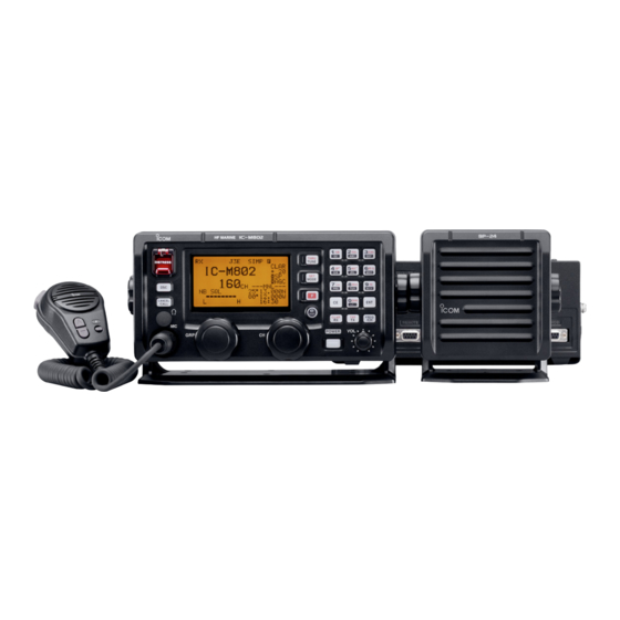
CONNECTION AND INSTALLATION ■ Supplied accessories The following accessories are supplied with IC-M802. q Microphone (HM-135) ������������ 1 w External speaker (SP-24) ���������� 1 e Mounting bracket kit for main unit ����� 1 set r Mounting bracket kit for remote controller (MB-81) �������������������... -
Page 64: Rear Panel Connections
When releasing: q Install the cable tie (base) onto the IC-M802 main unit side panel, or desired place near the main unit. Pull... -
Page 65: Ground Connection
CONNECTION AND INSTALLATION ■ Ground connection The transceiver and antenna tuner MUST have an ad- Best ground points equate RF ground connection. Otherwise, the overall • External ground plate efficiency of the transceiver and antenna tuner instal- • Copper screen lation will be reduced. -
Page 66: Antenna
See page 63 for pin assignment. Control cable (OPC-566 purchase separately) D Non-Icom tuner D AT-140 automatic antenna tuner Some non-Icom tuners may be used with the IC- See page 56. M802. Please consult your dealer if you wish to con- nect one. -
Page 67: Mounting
CONNECTION AND INSTALLATION ■ Mounting D Mounting location CAUTION: KEEP the transceiver and microphone Select a location that provides easy access to the con- at least 1 meter away from your ship’s magnetic troller for navigation safety, has good ventilation and is navigation compass. -
Page 68: Using The Optional Mb-75
CONNECTION AND INSTALLATION ■ Using the optional MB-75 The optional MB-75 flush mount is available for mount- CAUTION: KEEP the transceiver and microphone ing the controller and speaker to a flat surface such as at least 1 meter away from your ship’s magnetic an instrument panel. -
Page 69: Transceiver Dimensions
CONNECTION AND INSTALLATION ■ Transceiver dimensions... -
Page 70: Fuse Replacement
CONNECTION AND INSTALLATION ■ Fuse replacement CAUTION: DISCONNECT the DC power cable from The transceiver has 2 fuses (2 types) to protect in- the transceiver when changing a fuse. ternal circuitry, 1 fuse for the fuse holder on the DC power cable and 1 for inside. -
Page 71: Connector Information
CONNECTION AND INSTALLATION ■ Connector information Pin Pin name Description Specification CW and FSK keying input. Input level : Less than 0.6 V for transmit AF GND Ground line for AF signal. Input/output pin. Ground level : –0.5 to 0.8 V SEND Goes to ground when transmitting. - Page 72 CONNECTION AND INSTALLATION ■ Connector information (continued) AF/MOD Pin Pin name Description Specification Input impedance : 600 Ω MOD+ Modulation input from an external terminal unit. Input level : Approximately 0.77 V rms MOD– Coaxial ground for NMD+. Ground for digital equipment. Output impedance : 600 Ω...
-
Page 73: Specifications
SPECIFICATIONS • General • Transmitter • Frequency coverage • Output power (Unit: MHz) 1.6–27.5000 MHz 150/60/20 W p–p Receive 0.5–29.9999 Transmit 1.6–2.9999 4.0–4.9999 • Spurious emission : –62 dB 6.0–6.9999 8.0–8.9999 • Carrier suppression : 40 dB below peak output power 12.0–13.9999 16.0–17.9999 •... -
Page 74: Options
Approved Icom optional equipment is designed for optimal performance when used with an Icom transceiver. Icom is not responsible for the destruction or damage to an Icom transceiver in the event the Icom transceiver is used with equipment that is not manufactured or approved by... -
Page 75: Template
TEMPLATE ■ Remote controller (RC-25) ″ 110 mm; 4 ⁄ ″ 92 mm; 3 ⁄ 4–R11... -
Page 77: Speaker (Sp-24)
TEMPLATE ■ Speaker (SP-24) ″ 110 mm; 4 ⁄ ″ 92 mm; 3 ⁄ 4–R11... - Page 79 MEMO...
- Page 80 A-7096H-1US Printed in Japan 1-1-32 Kamiminami, Hirano-ku, Osaka 547-0003, Japan © 2013 Icom Inc.