
Related Manuals for Fisher & Paykel Classic Series


Summary of Contents for Fisher & Paykel Classic Series
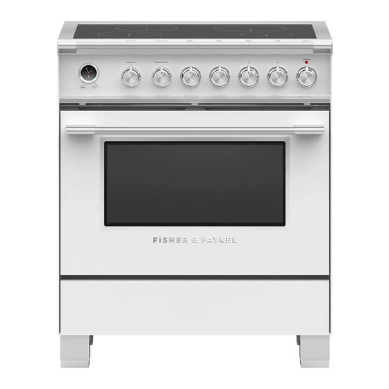
- Page 1 FREESTANDING COOKER OR30SDI & OR30SCI Induction & OR30SDE Glass Ceramic models INSTALLATION GUIDE US CA 591507D 10.19...
-
Page 2: Table Of Contents
CONTENTS Safety and warnings Parts supplied for installation Tools needed for installation (not supplied with the appliance) Model identification Prior to installation Product dimensions Clearance dimensions Fitting the optional backguard Location of electrical supply Ventilation requirements Fitting the adjustable feet Moving the range Installing the anti-tip bracket Electrical connection... -
Page 3: Safety And Warnings
SAFETY AND WARNINGS Installation IMPORTANT SAFETY INSTRUCTIONS! WARNING! Electrical shock hazard Save these instructions for the local inspectors use. ● ● Before carrying out any work on the electrical section of the appliance, To avoid hazard, follow these instructions carefully before installing or using this ●... - Page 4 SAFETY AND WARNINGS IMPORTANT SAFETY INSTRUCTIONS! GENERAL INSTALLATION INFORMATION Cleaning and servicing A risk of the appliance tipping over exists if the appliance is not installed in accordance ● ● with installation instructions. Service should only be performed by an authorized technician. ●...
-
Page 5: Parts Supplied For Installation
PARTS SUPPLIED FOR INSTALLATION Screws and plastic Cupped washer* Anti-tip bracket (1) Small screws and Bolt (1) Threaded nuts (2) Wood screws (8) Ground lead* washers (2) sleeve anchors (8) (3 wire permanent (4 wire permanent connection) connection) *Can be used in US only, for Canada it is mandatory to connect the range by using cordset with plug supplied. -
Page 6: Model Identification
MODEL IDENTIFICATION NOTE: Model features may vary 30” INDUCTION MODELS 30” CERAMIC MODELS OR30SDI6 OR30SDE6 OR30SCI6 PRIOR TO INSTALLATION Unpacking and handling Inspect the range to verify that there is no shipping damage. If any damage is detected, call the shipper and initiate a damage claim. Fisher & Paykel is not responsible for shipping damage. ●... -
Page 7: Product Dimensions
PRODUCT DIMENSIONS NOTE: Model features may vary Optional kickstrip shown is available (purchased separately) FRONT SIDE OR30SDI / OR30SCI OR30SDE PRODUCT DIMENSIONS inches (mm) inches (mm) Overall height of range min 35 3/4” (908) min 35 3/4” (908) max 37 5/8” (956) max 37 5/8”... -
Page 8: Clearance Dimensions
CLEARANCE DIMENSIONS Note #1 To eliminate the risk of burns or fire by reaching over heated surface units, cabinet storage space located above the surface units should be avoided. If cabinet storage is to be provided, the risk can be reduced by installing a rangehood that projects horizontally a minimum of 5 “... -
Page 9: Fitting The Optional Backguard
place. • The island trim is already fitted to the appliance while the backguard can be purchased as a FITTING THE OPTIONAL BACKGUARD Fig. 1.3a separate kit. Fig. 1.2 • If replacing the island trim with the backguard, assemble it by using the same screws/spacers used for fixing the island trim (figures 1.3a, Island trim and backguard 12 x... -
Page 10: Ventilation Requirements
VENTILATION REQUIREMENTS A suitable ventilation hood may be installed above the range. Fisher & Paykel has a choice of ventilation hoods designed to match the rest of our kitchen appliance family. See fisherpaykel.com or your local dealer for more details. Hood (inc. -
Page 11: Fitting The Adjustable Feet
FITTING THE ADJUSTABLE FEET Fitting the adjustable feet Fitting the adjustable feet covers (optional) The adjustable feet must be fitted to the base of the range before use. If using the adjustable feet covers fit these while the range is tipped over. Rest the rear of the range on a piece of the polystyrene packaging exposing the base for the fitting of the feet. -
Page 12: Moving The Range
MOVING THE RANGE IMPORTANT! When raising the range to upright position always ensure two ● ● people carry out this manoeuvre to prevent damage to the adjustable feet. Be careful: do not lift the range by the oven door handle, the ●... -
Page 13: Installing The Anti-Tip Bracket
INSTALLING THE ANTI-TIP BRACKET The anti-tip bracket has two components: the adjustable bracket ● ● the stability bracket ● ● IMPORTANT! You must install both parts of the anti-tip bracket and ensure they are properly fitted together to prevent the range from tipping. To fit the anti-tip bracket 1 Thread the bolt through the adjustable bracket and fix in place using the two supplied nuts. - Page 14 INSTALLING THE ANTI-TIP BRACKET 3 Fix the stability bracket in place. It can be fixed as follows: To the floor OR on the rear wall by 4 screws (supplied). ● ● To the floor AND on the rear wall by 8 screws (supplied). ●...
-
Page 15: Electrical Connection
ELECTRICAL CONNECTION IMPORTANT! WARNING! This cooker must be connected to the electricity supply only by an authorised person. Your cooker is supplied with a certified 4 prong NEMA 14-50P power cord for your protection against shock hazard and should be plugged directly into a properly grounded socket. - Page 16 ELECTRICAL CONNECTION 4-Wire Connection 3-Wire Connection (using supplied Ground lead) PERMANENT CONNECTION (HARD WIRING) 1 Loosen the L1 (black), L2 (red) and neutral (white) screws. 1 Loosen the L1 (black), L2 (red) and neutral (white) screws. US only, for Canada it is mandatory to connect 2 Mount the conduit fitting to the 1 1/8”...
-
Page 17: Final Checklist
FINAL CHECKLIST TO BE COMPLETED BY THE INSTALLER GENERAL Placement of unit. Specified clearance maintained to cabinet surfaces. Unit Level – front to back, side to side. All packaging material and tie straps removed. Island trim or optional backguard correctly attached. The anti-tip bracket is correctly installed. - Page 19 CUISINIÈRE NON ENCASTRÉE Modèles à induction OR30SDI et OR30SCI en verre céramique OR30SDE GUIDE D’INSTALLATION US CA 591507D 10.19...
- Page 20 TABLE DES MATIÈRES Consignes de sécurité et mises en garde Pièces fournies pour l’installation Outils requis pour l’installation (non fournis avec l’appareil) Identification du modèle Avant l’installation Dimensions du produit Dimensions de dégagement Installation du dosseret en option Emplacement de l’alimentation en électricité Exigences relatives à...
- Page 21 CONSIGNES DE SÉCURITÉ ET MISES EN GARDE Installation CONSIGNES DE SÉCURITÉ IMPORTANTES! MISE EN GARDE! Risque de choc électrique Conservez ces instructions pour permettre aux inspecteurs locaux de les consulter. ● ● Avant de procéder à tout travail sur la section électrique de l’appareil, Pour réduire les risques de danger, suivez attentivement ces instructions avant d’installer ●...
- Page 22 CONSIGNES DE SÉCURITÉ ET MISES EN GARDE CONSIGNES DE SÉCURITÉ IMPORTANTES! INFORMATIONS D’INSTALLATION GÉNÉRALES Nettoyage et entretien L’appareil pourrait basculer s’il n’est pas installé conformément aux instructions ● ● d’installation. Les travaux d’entretien ou de réparation doivent être effectués uniquement par ●...
-
Page 23: Pièces Fournies Pour L'installation
PIÈCES FOURNIES POUR L’INSTALLATION Vis et chevilles à douille Rondelle creuse* Anti-tip bracket (1) Petites vis et rondelles (2) Boulon (1) Écrous filetés (2) Vis à bois (8) Fil de masse* en plastique (8) (Connexion (Connexion permanente à 4 fils) permanente à... -
Page 24: Identification Du Modèle
IDENTIFICATION DU MODÈLE REMARQUE : Les caractéristiques du modèle peuvent varier MODÈLES À INDUCTION 30” MODÈLES EN CÉRAMIQUE 30” OR30SDI6 OR30SDE6 OR30SCI6 AVANT L’INSTALLATION Déballage et manutention Inspectez la cuisinière pour vous assurer qu’aucun dommage n’a été causé lors de l’expédition. En cas de dommage, communiquez avec l’expéditeur pour effectuer une demande d’indemnisation. ●... -
Page 25: Dimensions Du Produit
DIMENSIONS DU PRODUIT REMARQUE : Les caractéristiques du modèle peuvent varier Kickstrip en option est disponible (acheté séparément) AVANT CÔTÉ OR30SDI / OR30SCI OR30SDE DIMENSIONS DU PRODUIT pouces (mm) pouces (mm) Hauteur hors tout de la cuisinière min. 35 3/4” (908) min. 35 3/4” (908) max. -
Page 26: Dimensions De Dégagement
DIMENSIONS DE DÉGAGEMENT Remarque N° 1 Pour réduire les risques de brûlure ou d’incendie, évitez de ranger des objets dans les armoires situées au-dessus des éléments de surface. Si toutefois vous devez ranger des objets dans ces armoires, réduisez les risques en installant une hotte dont la partie saillante horizontale dépasse la partie inférieure des armoires suspendues d’au moins 5”... -
Page 27: Installation Du Dosseret En Option
place. • The island trim is already fitted to the appliance while the backguard can be purchased as a INSTALLATION DU DOSSERET EN OPTION Fig. 1.3a separate kit. Fig. 1.2 • If replacing the island trim with the backguard, assemble it by using the same screws/spacers used for fixing the island trim (figures 1.3a, 12 x 1.3b). -
Page 28: Exigences Relatives À La Ventilation
EXIGENCES RELATIVES À LA VENTILATION Une hotte de ventilation appropriée peut être installée au-dessus de la cuisinière. Fisher & Paykel a un choix de hottes de ventilation conçues pour correspondre le reste de notre famille d’appareils de cuisine. Voir fisherpaykel.com ou votre revendeur local pour plus de détails. Hotte Hotte (incl. combustible) -
Page 29: Installation Des Pattes Ajustables
INSTALLATION DES PATTES AJUSTABLES Installation des pattes ajustables Installation des revêtements de pattes ajustables (en option) Les pattes ajustables doivent être installées sur la base de la cuisinière avant l’utilisation. Si vous souhaitez utiliser les revêtements de pattes ajustables, installez-les pendant Appuyez la partie arrière de la cuisinière sur un morceau de l’emballage en polystyrène, que la cuisinière est basculée vers l’arrière. -
Page 30: Déplacement De La Cuisinière
DÉPLACEMENT DE LA CUISINIÈRE IMPORTANT! Pour éviter d’endommager les pattes ajustables, la cuisinière doit ● ● toujours être élevée en position verticale par deux personnes. Soyez prudent : ne soulevez pas la cuisinière par la poignée du four ● ● lorsque vous l’élevez en position verticale. Lors du déplacement de la cuisinière à... -
Page 31: Installation Du Support Antibasculement
INSTALLATION DU SUPPORT ANTIBASCULEMENT Le support antibasculement est constitué de deux composants : le support ajustable ● ● le support de stabilité ● ● IMPORTANT! Vous devez installer les deux pièces du support antibasculement et vous assurer qu’elles sont bien installées ensemble pour éviter le basculement de la cuisinière. Pour installer le support antibasculement 1 Faites passer le boulon dans le support ajustable et fixez-le en place à... - Page 32 INSTALLATION DU SUPPORT ANTIBASCULEMENT 3 Fixez le support de stabilité en place. Vous pouvez le fixer comme suit : Au sol OU au mur arrière à l’aide de 4 vis (fournies). ● ● Au sol ET sur la paroi arrière par 8 vis (fournies). ●...
-
Page 33: Raccordement Électrique
RACCORDEMENT ÉLECTRIQUE IMPORTANT! MISE EN GARDE! Cette cuisinière doit être raccordée à l’alimentation électrique par une personne autorisée. Votre cuisinière est dotée d’un cordon d’alimentation avec fiche à 4 broches certifié NEMA 14-50P; branchez la fiche directement dans une prise correctement mise à la terre. Ne coupez ou retirez en aucun cas la quatrième broche (mise à... - Page 34 RACCORDEMENT ÉLECTRIQUE Connexion à 4 fils Connexion à 3 fils (en utilisant le fil de masse fourni) CONNEXION PERMANENTE (CÂBLAGE DUR) 1 Desserrez les vis L1 (noire), L2 (rouge) et neutre (blanche). 1 Desserrez les vis L1 (noire), L2 (rouge) et neutre (blanche).
-
Page 35: Liste De Vérification Finale
LISTE DE VÉRIFICATION FINALE À ÊTRE REMPLIE PAR L’INSTALLATEUR GÉNÉRALITÉS Emplacement de l’appareil. Mesures de dégagement spécifiées respectées par rapport aux surfaces d’armoires. Appareil de niveau – de l’avant à l’arrière, d’un côté à l’autre. Matériaux d’emballage et courroies d’attache entièrement retirés. Garniture d’îlot ou dosseret en option correctement fixé.