
Related Manuals for Extreme Networks ExtremeSwitching 5320 Series


Summary of Contents for Extreme Networks ExtremeSwitching 5320 Series
- Page 1 ExtremeSwitching 5320 Series Hardware Installation Guide 9037258-00 Rev. AC May 2022...
- Page 2 Copyright © 2022 Extreme Networks, Inc. All rights reserved. Legal Notice Extreme Networks, Inc. reserves the right to make changes in specifications and other information contained in this document and its website without prior notice. The reader should in all cases consult representatives of Extreme Networks to determine whether any such changes have been made.
-
Page 3: Table Of Contents
Evaluate and Meet Cable Requirements......................24 Label Cables and Keep Accurate Records....................25 Install Cable................................25 Use RJ45 Connector Jackets........................29 Prevent Radio Frequency Interference (RFI)..................29 Meet Power Requirements............................30 Requirements for PoE Devices........................30 ExtremeSwitching 5320 Series Hardware Installation Guide... - Page 4 Changing the Switch OS via the Bootloader Menu.................. 67 Changing the Switch OS via the Startup Menu..................67 Logging In for the First Time on Fabric Engine..................68 Monitor the Switch........................... 69 5320 Series Switch LEDs............................69 Port LEDs in Default (SYS) Mode......................70 ExtremeSwitching 5320 Series Hardware Installation Guide...
- Page 5 Install Power Supply Units and Connect Power..................86 Select Power Supply Cords..........................86 Battery Notice................................87 Battery Warning - Taiwan............................87 EMC Warnings................................88 Taiwan BSMI Warning............................. 88 China CCC Warning............................88 Japan (VCCI Class A)...............................88 Korea EMC Statement............................. 88 Index................................89 ExtremeSwitching 5320 Series Hardware Installation Guide...
-
Page 6: Preface
ExtremeXOS 31.6 Command Reference Guide information about configuring Extreme Networks devices. Note If the information in an installation note or release note shipped with your Extreme Networks equipment differs from the information in this guide, follow the installation or release note. Text Conventions Unless otherwise noted, information in this document applies to all supported environments for the products in question. - Page 7 Default responses to system prompts are enclosed in square brackets. { x | y | z } A choice of required parameters is enclosed in curly brackets separated by vertical bars. You must select one of the options. ExtremeSwitching 5320 Series Hardware Installation Guide...
-
Page 8: Documentation And Training
Extreme Optics Compatibility Other resources such as white papers, data sheets, and case studies Extreme Networks offers product training courses, both online and in person, as well as specialized certifications. For details, visit www.extremenetworks.com/education/. Help and Support If you require assistance, contact Extreme Networks using one of the following methods: Extreme Portal Search the GTAC (Global Technical Assistance Center) knowledge base;... -
Page 9: Subscribe To Product Announcements
You can modify your product selections or unsubscribe at any time. Send Feedback The Information Development team at Extreme Networks has made every effort to ensure that this document is accurate, complete, and easy to use. We strive to improve our documentation to help you in your work, so we want to hear from you. -
Page 10: Extremeswitching 5320 Series Overview
5320-16P-4XE-DC Switch Features on page 17 The ExtremeSwitching 5320 Series is a family of feature-rich edge switches designed for the next- generation digital enterprise. The 5320 Series universal hardware provides end-to-end secure network segmentation, in addition to advanced policy capabilities, and offers a user-selectable choice of Extreme’s flagship switch operating systems. -
Page 11: Cooling
Use the disable stacking-support command to set the U1 and U2 ports in Ethernet mode. Stacking cables for 5320 Series switches are ordered separately. For information about SFP+ optical modules, see the Extreme Optics website. ExtremeSwitching 5320 Series Hardware Installation Guide... -
Page 12: Operating Temperatures
5320-16P-4XE models, both AC and DC, and fan off, support an operating range from 0°C (32°F) to 35°C (95°F). Feature Licensing The ExtremeSwitching 5320 Series switches support Unified Licensing, so that you can use them with multiple operating systems. There are two methods of acquiring feature licenses: manual or through ExtremeCloud IQ™ (XIQ). -
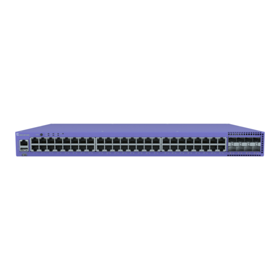
Page 13: 5320-48P-8Xe Switch Features
5 = 1/10Gb SFP uplink ports 1 = RJ-45 serial console port 3 = USB Micro-B console port 2 = USB Type-A port 4 = 10/100/1000BASE-T ports 6 = 10Gb SFP+ Universal Ports/stacking ports ExtremeSwitching 5320 Series Hardware Installation Guide... -
Page 14: 5320-24T-8Xe Switch Features
1 = RJ-45 serial console port 3 = USB Micro-B console port 2 = USB Type-A port 4 = 10/100/1000BASE-T ports 6 = 10Gb SFP+ Universal Ports/stacking ports The rear panel of the switch includes: • Grounding lug • 1 AC power inlet connector ExtremeSwitching 5320 Series Hardware Installation Guide... -
Page 15: 5320-24P-8Xe Switch Features
1 = RJ-45 serial console port 3 = USB Micro-B console port 2 = USB Type-A port 4 = 10/100/1000BASE-T ports 6 = 10Gb SFP+ Universal Ports/stacking ports The rear panel of the switch includes: • Grounding lug • 1 AC power inlet connector ExtremeSwitching 5320 Series Hardware Installation Guide... -
Page 16: 5320-16P-4Xe Switch Features
1 = RJ-45 serial console port 3 = USB Micro-B console port 2 = USB Type-A port 4 = 10/100/1000BASE-T ports 6 = 10Gb SFP+ Universal Ports/stacking ports The rear panel of the switch includes: • Grounding lug • 1 AC power inlet connector ExtremeSwitching 5320 Series Hardware Installation Guide... -
Page 17: 5320-16P-4Xe-Dc Switch Features
5 = 1/10Gb SFP uplink ports 1 = RJ-45 serial console port 3 = USB Micro-B console port 2 = USB Type-A port 4 = 10/100/1000BASE-T ports 6 = 10Gb SFP+ Universal Ports/stacking ports ExtremeSwitching 5320 Series Hardware Installation Guide... - Page 18 • 1 DC power inlet connector Figure 12: 5320-16P-4XE-DC Rear Panel 1 = Kensington lock 2 = DC power inlet connector 3 = Grounding lug 4 = Cable tie mount for power cord management ExtremeSwitching 5320 Series Hardware Installation Guide...
-
Page 19: Site Preparation
The physical installation site must meet the following requirements for a safe and successful installation: • Building and electrical code requirements • Environmental, safety, and thermal requirements for the equipment you plan to install • Equipment rack requirements 2. Evaluating and meeting cable requirements. ExtremeSwitching 5320 Series Hardware Installation Guide... -
Page 20: Operating Environment Requirements
Site Preparation After examining your physical site and verifying that all environment requirements are met, evaluate and compare your existing cable plant with the requirements of the Extreme Networks equipment to determine if you need to install new cables. 3. Meeting power requirements. -
Page 21: Set Up The Wiring Closet
Consult an electrical contractor for commercial building and wiring specifications. Control the Temperature Extreme Networks equipment generates a significant amount of heat. It is essential that you provide a temperature-controlled environment for both performance and safety. Install the equipment only in a temperature- and humidity-controlled indoor area that is free of airborne materials that can conduct electricity. -
Page 22: Control The Humidity Level
Table 5 summarizes the behavior of ExtremeSwitching switches when they experience high operating temperatures. Safeguards are built into all Extreme Networks switches and power supply units to minimize the risk of fire. Table 5: Thermal Shutdown and Restart Behavior Switch Model(s) -
Page 23: Rack Specifications And Recommendations
Because building codes vary worldwide, consult an electrical contractor to ensure proper equipment grounding for your specific installation. Provide Adequate Space for the Rack Provide enough space in front of and behind the switch so that you can service it easily. ExtremeSwitching 5320 Series Hardware Installation Guide... -
Page 24: Secure The Rack
Extra room on each side is optional. Warning Extreme Networks switches do not have a switch for turning power to the unit on and off. For systems using an AC power supply, power to the switch is disconnected by removing the wall plug from the electrical outlet. -
Page 25: Label Cables And Keep Accurate Records
Assign a unique block of sequential numbers to the group of cables that run between each pair of wiring closets. • Assign a unique identification number to each equipment rack. • Identify all wiring closets by labeling the front panel of your Extreme Networks equipment and other hardware. • Keep accurate and current cable identification records. •... - Page 26 Keep all ports and connectors free of dust. Figure 14: Properly Installed and Bundled Cable 1 = Ensure adequate slack and bend radius Handle Fiber Optic Cable Fiber optic cable must be handled carefully during installation. ExtremeSwitching 5320 Series Hardware Installation Guide...
- Page 27 Table 6: Cable Distances and Types Standard Media Type MHz•km Maximum Distance Rating (Meters) 1000BASE-SX 50/125 µm multimode fiber (850nm optical window) 50/125 µm multimode fiber 62.5/125 µm multimode fiber 62.5/125 µm multimode fiber ExtremeSwitching 5320 Series Hardware Installation Guide...
- Page 28 10BASE-T Category 3 and higher UTP cable – 1 Proprietary to Extreme Networks. Connections between two Extreme Networks 1000BASE-LX interfaces that use 10/125 µm single-mode fiber can use a maximum distance of 10,000 meters. ExtremeSwitching 5320 Series Hardware Installation Guide...
-
Page 29: Use Rj45 Connector Jackets
Routing UTP cable near equipment that could exhibit RF interference, such as ARC welding equipment • Routing UTP cable near electrical motors that contain coils • Routing UTP cable near air conditioner units • Routing UTP cable near electrical transformers ExtremeSwitching 5320 Series Hardware Installation Guide... -
Page 30: Meet Power Requirements
Extreme Networks equipment. The web page provides specifications for power cords in each country so that you can purchase cords locally. UPS (Uninterruptible Power Supply) Requirements... - Page 31 UPS transition time is the time required for the UPS to change from providing AC power derived from the utility (or mains) supply to providing AC power derived from the battery backup. UPS transition time is sometimes called UPS transfer time. ExtremeSwitching 5320 Series Hardware Installation Guide...
-
Page 32: Follow Applicable Industry Standards
Site Preparation UPS transition times vary between UPS models and implementations, but shorter transition times are preferred. For Extreme Networks stacking products, a UPS transition time of 20 milliseconds or less ensures optimum performance and minimizes service interruptions. For high-availability and fault-tolerant installations in which the switches use redundant power supply units (PSUs), ensure that each PSU in a switch is connected to a different UPS and that each UPS is powered by an independent AC supply. -
Page 33: Build Stacks
SummitStack cables. All connections between stack ports must be directly between switches. A stacking connection cannot pass through a third device, for example a Virtual Port Extender or an LRM/MACsec Adapter. ExtremeSwitching 5320 Series Hardware Installation Guide... -
Page 34: Build Basic Stacks
A switch stack can be thought of as a virtual chassis. Each switch (node) operates as if it were occupying a slot in a chassis and is controlled by the primary. The high-speed stacking links function like the backplane links of a chassis. ExtremeSwitching 5320 Series Hardware Installation Guide... - Page 35 For example, in a stack that combines 5520 series or 5420 series switches with 5320 series switches switch models, a 5520 series or 5420 series switch might provide more memory and more features than ExtremeSwitching 5320 Series Hardware Installation Guide...
-
Page 36: Summitstack Topologies
5320 series switch. Important The ExtremeSwitching 5320 series switches can also be stacked with themselves, or as the Primary node with ExtremeSwitching 5420 and 5520 as backups using Alternate stacking. The 5320 can only act as a Standby node in a 5420 or 5520 Primary configuration. The 5320 cannot act as a Backup node when the Primary node is either a 5420 or 5520. - Page 37 Each switch in the rack is connected to the switch above it and the switch below it. To complete the ring, a longer cable connects Switch 1 with Switch 8. ExtremeSwitching 5320 Series Hardware Installation Guide...
- Page 38 Connect your stack nodes in a ring topology, not a daisy-chain topology, for normal operation. Figure 22, the nodes delineated as the active topology are operating in a daisy-chain configuration, even though there is physically a ring connection in the stack. ExtremeSwitching 5320 Series Hardware Installation Guide...
-
Page 39: Use Ethernet Ports For Stacking (Summitstack-V Feature)
Guide. Use Ethernet Ports for Stacking (SummitStack-V Feature) On many Extreme Networks switches, you can reconfigure one or two 10-Gbps Ethernet data ports to operate as stacking ports. This feature, known as SummitStack-V or alternate stacking, means that you can use less expensive cables to connect the switches in a stack. - Page 40 5320-48P-8XE Front panel: U1, U2 None Not applicable 5320-48T-8XE 5320-24P-8XE 5320-24T-8XE 5320-16P-4XE 5320-16P-4XE-DC 5420F-8W-16P-4XE Front panel: U1, U2 None Not applicable 5420F-24P-4XE 5420F-24S-4XE 5420F-24T-4XE 5420F-16MW-32P-4XE 5420F-16W-32P-4XE 5420F-48P-4XE 5420F-48P-4XL 5420F-48T-4XE 5420M-24T-4YE 5420M-24W-4YE 5420M-16MW-32P-4YE 5420M-48T-4YE 5420M-48W-4YE ExtremeSwitching 5320 Series Hardware Installation Guide...
-
Page 41: Summitstack Terms
(2) a single stackable switch can manage the entire stack; and (3) configurable entities such as VLANs and link trunk groups can have members on multiple stackable switches. A stack consists of all connected nodes regardless of the state of the nodes. ExtremeSwitching 5320 Series Hardware Installation Guide... - Page 42 If and when the primary node fails, the backup node becomes the primary node and begins operating with the databases it has previously received. In this way, all other nodes in the stack can continue operating. ExtremeSwitching 5320 Series Hardware Installation Guide...
- Page 43 {detail} | detail }command. System uptime The amount of time that has passed since the last node role election. You can display the system uptime by entering the show switch {detail } command on the primary node. ExtremeSwitching 5320 Series Hardware Installation Guide...
-
Page 44: Plan To Create Your Stack
You must enable stacking-support individually for every switch in the stack that does not have stacking support enabled by default. • To disable stacking support, configure the switch data ports to use the Ethernet protocol instead of the stacking protocol. Use the disable stacking-support command. ExtremeSwitching 5320 Series Hardware Installation Guide... -
Page 45: Recommendations For Placing Switches For Stacked Operation
ExtremeXOS and Switch Engine 31.6 Feature License Requirements.) To view the Switch Engine software version on a node, restart the node and run the command: show version {detail | process name | images {partition partition} {slot slot_number} } . ExtremeSwitching 5320 Series Hardware Installation Guide... -
Page 46: Select Native And Alternate Stacking Ports
To select between the native and alternate stacking ports, use the following command for each switch in the stack: configure stacking-support stack-port [stack-ports | all] selection [native { |V40 |V80|V160|V200|V320 |V400} |alternate] Note Not all options are available for all switches. ExtremeSwitching 5320 Series Hardware Installation Guide... -
Page 47: Combine Switches From Different Series
Alternate stacking (10Gb link running at HG). Select Stacking Cables Stacking connections using the native stacking ports require stacking cables that are specific to the type of stacking port. These cables are available from Extreme Networks in lengths from 0.5 meter to 100 meters. Note... -
Page 48: Use The Extreme Stacking Tool
To the right of the Stack column, the tool displays statistics about available routes, supported software versions, and primary/backup recommendations. If you don't see statistics and other information, select the arrow (> symbol) to the immediate right of the Stack column. ExtremeSwitching 5320 Series Hardware Installation Guide... -
Page 49: Set Up The Physical Stack
In general, it is best to connect Stack Port 2 on one switch to Stack Port 1 on the switch with the next higher slot number. Although you can connect the switches in any order, connecting them as shown in these examples will produce better predictability and easier software configuration. ExtremeSwitching 5320 Series Hardware Installation Guide... - Page 50 It is essential to create an unbroken data path through all the switches in the stack. Use SummitStack-V160 Stacking A stacking rate of 160 Gbps can be achieved using certain configurations of Extreme Networks switches. For example, an X460-G2 switch can be connected to an X670-G2-48x-4q switch through 40-Gbps stacking connections that provide 160 Gbps full-duplex bandwidth.
- Page 51 SummitStack modules. For the second switch model, the stacking ports are on installed SummitStack stacking modules. The recommended order for connecting the stacking ports is the same as for the example in Example: Basic Stack with Eight Switches on page 51. ExtremeSwitching 5320 Series Hardware Installation Guide...
- Page 52 Port 2 on one switch is connected to Port 1 on the next connected switch. If the easy setup feature is used to configure the stack parameters, the assigned slot numbers will be as shown in the figure. ExtremeSwitching 5320 Series Hardware Installation Guide...
-
Page 53: Connect Your Stack To The Management Network
IP address configuration that will enable you to log in directly to each switch in the stack through its Ethernet management port. See the ExtremeXOS 31.6 User Guide for instructions to perform the software configuration for your stack. ExtremeSwitching 5320 Series Hardware Installation Guide... -
Page 54: Install Your Switch
Install Optional Components on page 60 Turn on the Switch on page 61 Before You Begin Before you attempt to install or remove an Extreme Networks switch, read the precautions in Safety Considerations for Installation on page 54. About This Task Extreme Networks switches fit into standard 19-inch equipment racks. -
Page 55: What You Will Need For The Installation
19, and ensure that you have the appropriate people and tools on hand. Installing Extreme Networks switches is easiest when there are two people to maneuver the switch and attach mounting hardware. Provide enough space in front of and behind the switch so that you can service it easily. Ensure that a minimum of 122 cm (48 in) in front of the rack and 76 cm (30 in) behind the rack. -
Page 56: Mount The Device On A Table
5320-24T-8XE, and 5320-24P-8XE. The two-post rack mount kit XN-2P-RMKIT-007 is required for models 5320-16P-4XE and 5320-16P-4XE-DC. Take care to load the rack so that it is not top-heavy. Start installing equipment at the bottom and work ExtremeSwitching 5320 Series Hardware Installation Guide... - Page 57 Figure 30: Flush-Mount: Attaching short mounting ears to models 5320-48P/T and 5320-24P/T Figure 31: Flush-Mount: Attaching longer mounting ears to 5320-16P models Figure 32: Mid-Mount: Attaching short mounting ears to models 5320-48P/T and 5320-24P/T ExtremeSwitching 5320 Series Hardware Installation Guide...
-
Page 58: Mount The Device On A Wall (5320-16P Models)
6. Mount the switch on the wall by screwing a provided wood screw through each hole in the wall- mounting ears into the anchors. Ensure that all screws are securely fastened and that the switch is firmly attached to the wall. ExtremeSwitching 5320 Series Hardware Installation Guide... -
Page 59: Mount The Device Under A Table (5320-16P Models)
6. Mount the switch under the table by screwing a provided wood screw through each hole in the mounting ears into the anchors. Ensure that all screws are securely fastened and that the switch is firmly attached to under the table. ExtremeSwitching 5320 Series Hardware Installation Guide... -
Page 60: Connect Network Interface Cables
ExtremeSwitching switches support the use of pluggable transceivers and cables in the SFP+, SFP28, QSFP+, and QSFP28 formats. For a list of the optical components supported with ExtremeSwitching devices, see the Extreme Optics website. ExtremeSwitching 5320 Series Hardware Installation Guide... -
Page 61: Pluggable Transceiver Modules
Connect DC Power DC power and grounding cables are not included with the power supply. You can purchase #16 AWG copper DC power cables and ground wire for use in the US and Canada from Extreme Networks or from your local supplier. - Page 62 Tighten the screw on the top of the ground terminal connector to 2.2 in‑lb (0.25 N m). 6. Insert the connector into the slot on the power supply. ExtremeSwitching 5320 Series Hardware Installation Guide...
- Page 63 When the PWR LED has turned green, follow the instructions in Activate and Verify the Switch on page If the PWR LED does not turn green, refer to 5320 Series Switch LEDs on page 69 for troubleshooting information. ExtremeSwitching 5320 Series Hardware Installation Guide...
-
Page 64: Activate And Verify The Switch
The default communication protocol settings for the serial console interface are: • Baud rate: 115200 • Data bits: 8 • Stop bit: 1 • Parity: None ExtremeSwitching 5320 Series Hardware Installation Guide... -
Page 65: Logging In For The First Time On Switch Engine
5. Enter show version. The switch serial number is displayed, as highlighted in the following example. Make a note of this number for future reference. Transit.3 # show version Switch : 801106-00-02 TB032146K-H0021 Rev 02 BootROM: 3.4.2.8 ExtremeSwitching 5320 Series Hardware Installation Guide... -
Page 66: Configure A Vlan And A Virtual Router To Use A Front Panel Port For Local Management
10.69.8.1 vr vr-mymgmt 8. Enter save to save your configuration changes so that they will be in effect after the next system reboot ExtremeSwitching 5320 Series Hardware Installation Guide... -
Page 67: Changing The Switch Os Via The Bootloader Menu
OS from the Startup menu on initial activation only by completing the following steps: Procedure 1. Connect to the switch via telnet, SSH, or console with a baud rate of 115200. ExtremeSwitching 5320 Series Hardware Installation Guide... -
Page 68: Logging In For The First Time On Fabric Engine
When prompted for the password, enter rwa. When you are logged in with the role-based authentical level of rwa, you can configure the login and password values for the other role-based authentication levels. ExtremeSwitching 5320 Series Hardware Installation Guide... -
Page 69: Monitor The Switch
69 The following topics help you monitor the status of the switch while it is operating. 5320 Series Switch LEDs ExtremeSwitching 5320 Series front panel port LEDs, as described in the following table: Table 14: 5320 Series Port LEDs Color/State... -
Page 70: Port Leds In Default (Sys) Mode
SPD LED. SPD mode is used to help determine the operational speed of a port. Color and blink pattern indicate speeds, as referenced by the following table: Table 16: Port LEDs in SPD Mode Color/State Speed Steady green 10Mbps Blinking green 100Mbps Solid amber 1000Mbps ExtremeSwitching 5320 Series Hardware Installation Guide... -
Page 71: Port Leds In Stk Mode
Table 17: Port LEDs in STK Mode Color/State Speed Steady green The slot corresponding to the port number of the LED is present. Blinking green This slot has a slot number corresponding to the port number of the blinking LED. ExtremeSwitching 5320 Series Hardware Installation Guide... -
Page 72: Technical Specifications
Width: 17.3 inches ( 44.0 cm) Length: 13.0 inches (33.0 cm) Table 19: 5320 Unpackaged Weight 5320-16P-4XE 7.9 lb (3.6 kg) 5320-16P-4XE-DC 7.7 lb (3.5 kg) 5320-24T-8XE 8.3 lb (3.78 kg) 5320-24P-8XE 9.3 lb (4.22 kg) ExtremeSwitching 5320 Series Hardware Installation Guide... -
Page 73: Fan And Acoustic Noise
The speed of the fan increases only when the temperature of the device increases. Fan speed is not dependent on any fan failures. Table 22: 5320 Fan Speed Model Fan Speed Fan RPM (typical) 5320-48T-8XE Maximum (58%) 10500 Low (10%) ExtremeSwitching 5320 Series Hardware Installation Guide... -
Page 74: Mean Time Between Failures (Mtbf)
5320-16P-4XE-DC L-R, 2x internal 1,265,083 491,249 fans, fan-less below 35°C CPU and Memory CPU/Memory Trident3-X1/X2 internal ARM A72 CPU 1 GB DDR4 ECC memory 1 GB SLC NAND Flash Memory 8 MB SPI flash ExtremeSwitching 5320 Series Hardware Installation Guide... -
Page 75: Standards And Environmental Data
FCC CFR 47 part 15 Class A (USA) ICES-003 Class A (Canada) European EMC standards EN 55032 Class A EN 55024 EN 61000-3-2,2014 (Harmonics) EN 61000-3-3 2013 (Flicker) EN 300 386 (EMC Telecommunications) 2014/30/EU EMC Directive ExtremeSwitching 5320 Series Hardware Installation Guide... - Page 76 Temperature range: 0°C to 50°C (32°F to 122°F) Humidity: 10% to 95% relative humidity, non-condensing Altitude: 0 to 3,000 meters (9,850 feet) Operational shock (half sine): 294m/s 2 (30G), 11ms in 3 axis. 6 shocks per axis. 3 axis. ExtremeSwitching 5320 Series Hardware Installation Guide...
-
Page 77: Power Specifications
Power supply input socket and cord IEC/EN 60320-1/C16 AC input receptacles Power cord wall plug Refer to Power Cord Requirements for AC-Powered Switches and AC Power Supplies on page 78 Efficiency Minimum efficiency: 90% at maximum power output 115VAC ExtremeSwitching 5320 Series Hardware Installation Guide... -
Page 78: 550 W Ac Power Supply
36 - 72V, 9.8 A max Nominal input 48Vdc DC output 12V/120W, 54V/200W Power Cord Requirements for AC-Powered Switches and AC Power Supplies An AC power cord is not included with the AC power supply. ExtremeSwitching 5320 Series Hardware Installation Guide... -
Page 79: Console Connector Pinouts
TXD (transmit data) DTR (data terminal ready) GND (ground) DSR (data set ready) RTS (request to send) CTS (clear to send) Figure 40 shows the pinouts for a 9-pin to 25-pin (RS-232) null-modem cable. ExtremeSwitching 5320 Series Hardware Installation Guide... - Page 80 RJ45 console port on the ExtremeSwitching switches. Table 34: RJ45 Console Port on Switch Function Pin Number Direction RTS (request to send) DTR (data carrier detect) TXD (transmit data) GND (ground) — GND (ground) — ExtremeSwitching 5320 Series Hardware Installation Guide...
- Page 81 Table 35: Pinouts for an RJ45 to DB-9 Adapter Signal RJ45 Pin DB-9 Pin CTS (clear to send) DTR (data carrier detect) TXD (transmit data) GND (ground) GND (ground) RXD (receive data) DSR (data set ready) RTS (request to send) ExtremeSwitching 5320 Series Hardware Installation Guide...
-
Page 82: Safety And Regulatory Information
Only trained and qualified service personnel (as defined in IEC 60950-1 and AS/NZS 3260) should install, replace, or perform service to Extreme Networks switches and their components. Qualified personnel have read all related installation manuals, have the technical training and experience necessary to be aware of the hazards to which they are exposed in performing a task, and are aware of measures to minimize the danger to themselves or other persons. -
Page 83: General Safety Precautions
Make sure that your power supplies meet the site DC power or AC power requirements of all the network equipment. • Racks for Extreme Networks equipment must be permanently attached to the floor. Failure to stabilize the rack can cause the rack to tip over when the equipment is removed for servicing. •... -
Page 84: Maintenance Safety
Install all cables in a manner that avoids strain. Use tie wraps or other strain relief devices. Fiber Optic Ports and Optical Safety The following safety warnings apply to all optical devices used in Extreme Networks equipment that are removable or directly installed in an I/O module or chassis system. -
Page 85: Gbic, Sfp (Mini-Gbic), Qsfp+, Xenpak, And Xfp Regulatory Compliance
GBIC, SFP (Mini-GBIC), QSFP+, XENPAK, and XFP Safety and Regulatory Information Regulatory Compliance GBIC, SFP (Mini-GBIC), QSFP+, XENPAK, and XFP Regulatory Compliance Extreme Networks pluggable optical modules and direct-attach cables meet the following regulatory requirements: • Class 1 or Class 1M Laser Product •... -
Page 86: Install Power Supply Units And Connect Power
When you install DC power supplies or connect DC power: • Extreme Networks DC power supplies do not have switches for turning the unit on and off. Make sure that the DC circuit is de-energized before connecting or disconnecting the DC power cord at the DC input power socket. -
Page 87: Battery Notice
Il y a risque d’explosion si la pile est remplacée par un type de pile incorrect. Éliminez les piles usées en conformité aux règlements locaux d'élimination des piles. Battery Warning - Taiwan About This Task ExtremeSwitching 5320 Series Hardware Installation Guide... -
Page 88: Emc Warnings
This is a Class A product based on the standard of the VCCI Council. If this equipment is used in a domestic environment, radio interference may occur, in which case the user may be required to take corrective actions. Korea EMC Statement ExtremeSwitching 5320 Series Hardware Installation Guide... -
Page 89: Index
BICSI 24 conventions building codes 20 notice icons 6 Building Industry Consulting Service International., see BICSI text 6 cords requirements 78 selecting 86 cable ANSI standards 32 bend radius 26 bundling 25 daisy chain topology 38 category 5 25 data port 43 fiber optic 26, 60 ExtremeSwitching 5320 Series Hardware Installation Guide... - Page 90 Index DB-9 console connector pinouts 79 first device login 65 DB-9 pinouts 79 first switch login 68 DC power frequency, see radio frequency interference (RFI) connecting to switch 61 design standards 32 devices grounding initial login 65 racks 23 distances requirements 32 cables 27 wiring closet 21 documentation feedback 9 location 8 dual master condition 38 hitless failover 43 humidity 22 Easy-Setup 44...
- Page 91 Index native stacking 41 rack specifications native stacking ports 34 grounding 23 network interface connections 60 securing to floor 24 node address 43 space requirements 23 node role radio frequency interference (RFI) definition 42 patch panel installation 25 election 43 preventing 29 notices 6 redundancy null-modem cable pinouts 79 in a stack 35 regulatory information 82 restricted 21 restricted access 21 operating environment requirements 21...
- Page 92 Index stacking (continued) redundancy 35 under the table-mounting ring topology 37 switches 55, 56, 58, 59 single-rack 50, 51 unshielded twisted pair, see UTP cable slot number 34 UPS (uninterruptible power supply) stack number indicator 34 requirements 30 SummitStack-V160 50 selecting 31 terminology 41 transition time 31 tool 48 UTP cable top of rack 52 bend radius 25 troubleshooting 34 category 5 25...