Table of Contents
Advertisement
Quick Links
Operating and Installation Instructions Manual
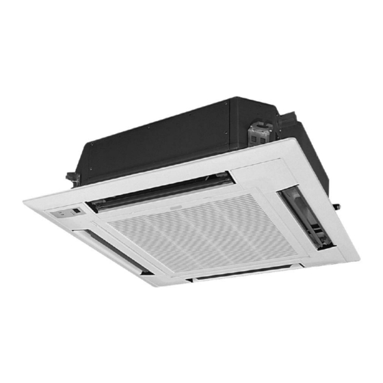
Cassette Type Air Conditioner (With Wire Controller)
Thanks for your selection of FIHSER Air-Conditioning Unit. Before use, please read this
instruction manual carefully and keep it properly to ensure correct use of this machine.
Unit Model:
Indoor Unit
FSK-180B-EU
FSK-240B
FSK-360B
FSK-360B
FSK-450B
Outdoor Unit
FSO-180B
FSO-240B
FSO-360B
FSO-360-3F
FSO-450B-3F
Advertisement
Table of Contents

Related Manuals for Fisher FSK-180B-EU


Summary of Contents for Fisher FSK-180B-EU
- Page 1 Operating and Installation Instructions Manual Cassette Type Air Conditioner (With Wire Controller) Unit Model: Indoor Unit Outdoor Unit FSK-180B-EU FSO-180B FSK-240B FSO-240B FSK-360B FSO-360B FSK-360B FSO-360-3F FSK-450B FSO-450B-3F Thanks for your selection of FIHSER Air-Conditioning Unit. Before use, please read this...
-
Page 3: Table Of Contents
CONTENTS 1、 Names and functions of parts………………………………………...…...…..1 2、 Safety cautions……………………………..……………..……………….…….3 3、 Wire controller (standard fitting) …………………………………………….5 4、 Remote control operation procedure ( standard fitting) …………………….13 5、 Weekly timer ( optional fitting) ………………………………………………23 6、 Wire controller (with week timer functions) ………..……………...….……25 7、... -
Page 4: 1、 Names And Functions Of Parts
1. Names and functions of parts indoor unit outdoor unit FSK-180B-EU FSO-180B FSK-240B FSO-240B... - Page 5 indoor unit outdoor unit FSK-360B FSO-360B FSK-360B FSO-360B-3F FSK-450B FSO-450B-3F...
-
Page 6: 2、Safety Cautions
2、Safety cautions ●Read the following carefully to assure safe use. NOTE: Children should be supervised to ensure that they do not play with the appliance. - Page 7 NOTE: This appliance is not intended for use by persons (including children) with reduced physical, sensory or mental capabilities, or lack of experience and knowledge, unless they have been given supervision or instruction concerning use of the appliance by a person responsible for their safety.
-
Page 8: 3、Wire Controller(Standard Fitting
3、Wire controller(standard fitting) Never install the wire controller in a place where there is water leakage. Avoid bumping, throwing, tossing or frequently opening the wire controller. Fig.1... - Page 9 1) ON/OFF (Fig.2) MODE ★ Press this button the unit will start. ★ When repress the button, the unit will stop running. SWING TIMER ON/OFF Fig 2 2) Fan control(Fig. 3) (The relevant contents are shown in the figure.) ★ Press this button to change the fan speed of: MODE ★...
- Page 10 remote control signal will be shielded too, the setting temp. will display “CC”. ★ The set temperature range under each mode: HEAT -------- 16℃~30℃ COOL -------- 16℃~30℃ DRY -------- 16℃~30℃ FAN -------- The temp. cannot be set up AUTO -------- The temp. cannot be set up 4)Swing mode set up(Fig.5) ★...
- Page 11 ★ In “DRY” mode, the “DRY” icon will light on. The inner fan will run at low fan speed in a certain range. This DRY efficiency in this mode is more obvious than the one in COOL mode, and the power saving efficiency is better. ★...
- Page 12 7) Outer ambient temperature display (Fig. 8) Under normal condition, “ENV” will display the room MODE ambient temperature, at unit turned on, or unit turned off status, press “SWING” button last for 5 seconds, the LCD will display “OUT ENV”. SWING TIMER If tested the outdoor temperature is the positive value,...
- Page 13 buttons to set cooling temperature upper limit, it will flash and display at ambient temperature, ( the setting range is 16-30) , and press “ON/OFF” button to confirm. NOTE:The upper limit temperature should not be lower than the setting lower limit temperature. If upper limit temperature is lower than the lower limit temperature, the system will default.
- Page 14 9) MEMORY function setup (Fig. 10) Press and hold the “MODE” key for 10 seconds when the unit is shut off to switch set values so as to decide if the unit operating status or shut off status shall be memorized after a power fail.
- Page 15 11) Debug Function Setting Debug Function(Setting of Ambient Temp. Sensor) When the unit is shut off, press the “FAN” key and the “SLEEP” key simultaneously to activate the debug menu. Now the LCD displays “DEBUG”. Press the “MODE” key to select setting item and use the “...
-
Page 16: 4、Remote Control Operation Procedure(Standard Fitting
4、Remote control operation procedure(standard fitting) ★ Name and Function-Remote Control Note: ● Be sure that there are no obstructions between receiver and remote controller. ● Don’ t drop or throw the remote controller . ● Don’ t let any liquid in the remote controller and put the remote controller directly under the sunlight or any place where is very hot. - Page 17 ★ Name and Function-Remote Control. (Remove the cover ) Note: This type of remote controller is a kind of new current controller. Some buttons of the controller which are not available to this air conditioner will not be described below. Operate on unmentioned buttons would not impact on the normal use.
- Page 18 ★ COOL mode operation procedure According to difference between room temp. and set temp., microcomputer can control ● cooling on or not. If room temp. is higher than set temp., compressor runs at COOL mode. ● If room temp. is lower than set temp., compressor stops and only indoor fan motor runs. ●...
- Page 19 ★ HEAT mode operation procedure ●If room temp. is lower than set temp., compressor runs at HE AT mode; ●If room temp. is higher than set temp., compressor and outdoor fan motor stop, only indoor fan motor runs. ●Set T EMP. should be in range of 16℃to 30℃...
- Page 20 ★DRY mode operation procedure ● If room Temp. is more than 2 below Set TEMP. , compressor and outdoor unit fan motor ℃ stop, indoor unit fan motor runs at low speed. ● If room Temp. is between ± of Set TEMP. , the compressor and outdoor unit fan motor ℃...
- Page 21 ★ AUTO mode operation procedure ●According to room temp. microcomputer can automatically set COOL.HEAT.DRY operation mode, so as far best effect. ● At AUTO mode operation, standard TEMP. is 26℃ for COOL mode, 24℃ for DRY mode and 20℃ for HEAT mode.
- Page 22 ★FAN mode operation procedure Connect the unit to power supply. Press the “ON/OFF” key. Press the mode key to select the “FAN” mode. The unit shall operate under “FAN” mode. Press the “FAN” key to select from high, medium and low speed.
- Page 23 ★TIMER operation procedure...
- Page 24 ★ SLEEP mode operation procedure ●When the unit is cooling or drying, if SLEEP operation is set, TEMP. would increase 1℃ in 1 hour and 2℃ in 2 hours. Indoor fan motor runs at low speed. ●When the unit is heating , if SLEEP operation is set, TEMP. would decrease 1℃ in 1 hour and 2℃...
- Page 25 ★How to inser t batteries...
-
Page 26: 5、Weekly Timer(Optional Fitting
5、Weekly timer(optional fitting) ★ Week Timing Controller (With Centralized Control Function) Centralized Control and Week Timer Functions: The centralized controller and the weekly timer are integrated in the same wire controller. The system has both the centralized control and the week timing functions. Up to 16 sets of units can be controlled simultaneously by the centralized controller (weekly timer). - Page 27 control can be done through shield setting on WEEKLY TIMER. Mode selection and temperature adjustment and other operations are done through the manual control at every unit. Note: 1、 For upper unit checks 16 lower units consecutively, there will be no more than 16 seconds delay when setting works till unit responds.
-
Page 28: 6、 Wire Controller (With Week Timer Functions)
6 .Wire controller (with week timer functions) WARNING! ● Never install the wired controller where there is water leakage. ● Never knock, throw or frequently open the wired controller. TIMER Fig.3 Each part of wired controller Timing Display Swing Status Display Ambient Temperature Display Timer interval Display Energy Saving Status Display... - Page 29 1) ON/OFF(Fig.4) Press the “ON/OFF” button, the unit will start running. Press the “ON/OFF” button again, the unit will stop running. SWING TIMER Fig.4 2)Fan Control (Fig.5 is about display region and the same as following figures.) When press FAN button once, the fan speed will be changed as follow: TIMER In DRY mode: the fan speed will be set at low automatically.
- Page 30 Setting temperature range under each mode: HEAT -------- 16℃~30℃ COOL -------- 16℃~30℃ -------- 16℃~30℃ -------- can not be set Auto mode is divides into new auto mode and old auto mode. NEW AUTO MODE --------------16℃~30℃ OLD AUTO MODE ---------- can not be set 4)Swing Setting (Fig.7) Press SWING button, SWING will be displayed on the LCD, in which case, the unit is under swing status.
- Page 31 the outdoor unit will be frosted resulting in low efficiency of heating, in which case, the controller will automatically start to defrost with DEFROST displayed. Note: No heating for cooling-only unit and auto mode will be shielded after setting energy saving. Timer Setting (Fig.9, 10, 11) Timer function in this wired controller conneted with weekly timer is invalid and wired controller will be...
- Page 32 In timing setting mode, press MODE button to select any desired setting object: Week (1-7), timer interval (1-4), timing (Timer on or Timer off time), min. part or hour part of time, and then press▲ or ▼ button to adjust this object, which is fixed by pressing TIMER button or can be canceled by pressing Timer again.
- Page 33 In deleting timing status, press ▲ or ▼ button to select one day of a week, and then press TIMER button confirm which case, ”dd” displayed .The day also can be canceled by pressing TIMER button without “dd” displayed. At last, press ON/OFF button to quit the setting after finish.(Fig.15) TIMER 7)...
- Page 34 set temp is displayed and set temp during setting is displayed and blinking. Press▲ and ▼ to set lower-limit cooling temp ( setting range is16-30) and then press ON/OFF to fix .Press ▲ and ▼ to set upper-limit cooling temp, which will be displayed where ambient temp is displayed (setting range is 16-30), and then press ON/OFF to fix.
- Page 35 memorize startup and stop status of the unit or not at unit.01 displayed in the region of displaying setting temp indicates memorizing start and stop status of the unit after power off .02, quit by pressing ON/OFF button ,indicates not memorizing.
- Page 36 11) Debug Function Setting Debug Function(Setting of Ambient Temp. Sensor) When the unit is shut off, press the “FAN” key and the “SLEEP” key simultaneously to activate the debug menu. Now the LCD displays “DEBUG”. Press the “MODE” key to select setting item and use the “...
-
Page 37: 7、Optimum Operation
7、Optimum operation... -
Page 38: 8、Trouble Shooting
8、Trouble shooting ★ Warning ● In case of something abnormal (such as bad smell), shut of fthe power switch immediately and contact service cent.er ● Do not repare the air conditioner by yourself because wrong repair may cause fire,please contact service center to do it for you ★Check item shown below before contacting service center. - Page 39 ★ The following are not troubles...
-
Page 40: 9、 Installation Notes
9、Installation notes(This should be done by professional) -
Page 41: 10、Care And Maintenance
10、Care and maintenance Please cut off the power supply after you used the air conditioner. Cut off power supply before cleaning (2 and 3 should be done by professional) (Done by professinal) -
Page 42: 11、 Instructions Of Unit Installation
11.1 nstall of the cassette type indoor unit A Schematic diagram of installation spaces 、 Models H mm FSK-180B-EU FSK-240B FSK-360B FSK-450B B 、 Select install location of the indoor unit 1. Obstruct should put away from the intake or outlet vent of the indoor unit so that the airflow can be blown though all the room. - Page 43 D、Dimension of ceiling opening and location of the hoisting screw (M10) R efrigerant pipe H oisting screw (X4) 680( G aps betw een hoisting screw rods 840( Indoor unit 890( C eiling opening 950( D ecorated surface boards FSK-360B FSK-450B FSK-180B-EU FSK-240B...
- Page 44 ☆ The drilling of holes in the ceiling must be done by the professional personnel. Installation stands for main body of the unit Ceiling Above 20 Fig 1 Notes: The dimension for the ceiling openings with * marks can be as large as 910mm. But the overlapping sections of the ceiling and the decorated surface boards should be maintained at no less than 20mm.
- Page 45 ☆ Please refer to the install cardboard about the dimensio of ceiling opening ☆ The central mark of the ceiling opening is marked on the install cardboard ☆ Install the install cardboard on the unit by bolt piece and fix the angle of the drainage pipe at the outlet vent by bolt.
- Page 46 Note: 1、The standard pipe length is 5m,When the length(L) of the connecting pipe is less than or equals 7m,there is no need to add refrigerant. If the connecting pipe is longer than 7m,it is required to add refrigerant,in the above table,the amounts of refrigerant to be added for the models are listed for each additional meter of pipe length.
- Page 47 ☆ Only use median sponge to entwine the wiring interface of the gas pipe and heat preservation sheath of the gas collection tube. Drainage hose G、 1. Install the drain hose ☆ The diameter of the drain hose should be equal or bigger than the connection pipe’s. ( The diameter of polythene pipe: Outer diameter 25mm Surface thickness ≥1.5mm) ☆...
- Page 48 Roof Hoisting stand Within 300mm 1-1.5m below 280mm Drain hose Drain raising hose 220mm Clamp(attachment) Ceiling Instruction ☆ The slant gradient of the attached drain hose Drain hose(attachment) should be within 75mm so that the drain hole doesn’t has to endure the unnecessary outside force. ☆...
- Page 49 11.2 Electric wiring 1、All field supplied parts and materials must conform to local laws and regulations. 2、For electric wiring, refer to WIRING DIAGRAM attached to the unit body. 3、All wiring must be performed by a skilled technician. 4、An all-pole disconnection switch having a contanct separation of at least 3mm in all poles should be connected in fix wiring.
- Page 50 Signal Cord Power: 220V~ 50Hz ● Precautions: Be sure to connect the indoor unit and outdoor unit at right poles. 11.3 Installation of panel Set the panel to the indoor unit body by matching the position of the swing flap motor of the ●...
- Page 51 Fig.4 Fig 4 ● Precautions 1. Improper screwing of the screws may cause the troubles shown in Fig.5 Fig.5 2. If gap is still left between the ceiling and the panel after screwing the screws, readjust the height of the indoor unit body (Refer to Fig.6)
- Page 52 Fig.6 ● After fixing be sure no gap left between the ceiling and the panel 3、Wiring of the decoration panel. Connect the joints for swing flap motor lead wire (at 2 places) installed on the panel (Refer to Fig.7)
- Page 53 11.4 Install of outdoor unit A、Profile Dimensions of Outdoor Unit Unit: mm Model FSO-450B-3F FSO-360B FSO-180B FSO-240B FSO-360-3F Item 1018 1018 1032 1250 B、Schematic diagram of installation spaces C、Precautions on Installation of Outdoor Unit To ensure the unit in proper function selection of installation location must be in accordance with following principles: (1) Outdoor unit shall be installed so that the air discharged by outdoor unit will not return and that...
- Page 54 enough air. Ensure that there is no obstacle for the air intake and exhaust of the outdoor unit. If there is any obstacle blocking the air intake or exhaust, remove it. (3) Place of installation shall be strong enough to support the weight of outdoor unit, and it shall be able to insulate noise and prevent vibration.
- Page 55 the vacuum pump, having the low-pressure end linking to the inlet for refrigerant. 3. Starting the vacuum pump, when the indicator turns to-1 bar, closing the low pressure handle and stopping vacuumize. keep for 15 minutes, ensuring the pressure of the vacuum watch remains. 4.
- Page 56 Caution: (1) Do not wrap the protective tape too tight, otherwise the efficiency of thermal insulation may be decreased. Ensure that the condensate drainage flexible tube is separate from the bundled pipes. (2) After the protective work is completed and the pipes are wrapped, use seal material to block the hole in the wall, so as to prevent rain and wind from entering the room.
- Page 57 Name Wall Surface Bottom Plate of Wire Controller Screw M4X10 Panel of Wire Controller 2. The communication distance between the main board and the wire controller can be as far as 20m (The standard distance is 8m). 3. The wire controller shall not be installed in a place where there is water drop or large amount of water vapor.
- Page 58 (4) Put the screw through the loop of the single wire and fix the loop at the terminal board. 2. Connection of multiple twisted wires (1) Use wire stripper to strip the insulation layer (10mm long) from the end of the multiple twisted wires.
- Page 59 (3) Connect the power supply cable to the “L, N” Caution: terminals and Take great care when carrying out the the grounding screw. following connections, avoid malfunction air-conditioning unit (4) Use cable fastener to bundle and fix the cable. because of electromagnetic interference. (1) The signal line of the wire controller must 2.
- Page 60 short circuit and overload. The on spot connection should refer to the circuit diagram, witch is stuck on the unit body The model selection recommend table for air switch and power cable Warning The section area of cables selected by users must not be smaller than the specifications show diagram 2×0.75 (H05RN-F) Communication Cords:...
- Page 61 The power cable communication wire co nnection between indoor and outdoor Warning: The signal wire between indoor and outdoor unit shall be installed in the shielded bushing. Schematic Diagram of Unit Line Connection: FSK-180B-EU FSO-180B FSK-240B FSO-240B FSO-360B FSK-360B FSO-360B-3F...
-
Page 62: 12、 Test Operation
12.Test operation 1. Prepare for test (1) Do not turn on the power switch before all installation is finished. (2) Connect wires correctly and firmly. (3) Open the check valve. (4) Remove all dust. 2. Testing (1) Turn on the power switch and press ON/OFF button. (2) Press MODE button select COOL, HEAT, FAN, etc to test whether it operates normally. - Page 63 The air conditioner select from COOL, HEAT, DRY, FAN modes automatically. * On operating, press the AUTO button, the air conditioner will stop. The “TEST” button on the cover No.Ⅱis specially for testing the air conditioner. When pressing it ,the air conditioner will be forced to operate or stop. Do not press it when air Note: conditioner is in normal operation.
-
Page 64: Error Display On The Panel
Error Display : Instructions to the Error Indicating Lamps on the Cassette Type Unit Timer Indicating Lamp (yellow) Compressor Indicating Lamp (green) Running Indicating Remote Controller Lamp (red) Receiver Instructions to the error indicating lamps on the dash receiver of the cassette type unit are described below. Once the handheld controller works, the error code will be displayed on it. -
Page 65: Appendix
Appendix: Air conditioner nominal working condition and working range: Indoor side Outdoor side Test condition DB(℃) WB(℃) DB(℃) WB(℃) Nominal cooling Nominal heating ―― Rated cooling Low temp. cooling 18(-7) ―― Rated heating ―― Low temp. heating ―― -7 -8 Note: 1. - Page 68 This product must not be disposed together with the domestic waste. This product has to be disposed at an authorized place for recycling of electrical and electronic appliances. 66129906996...