Table of Contents
Advertisement
Quick Links
Advertisement
Table of Contents

Related Manuals for Hawking HNC320W


Summary of Contents for Hawking HNC320W
- Page 2 Trademarks & Copyright Windows 95/98/ME and Windows NT/2000/XP are registered trademarks of Microsoft Corp. All other brands and product names are trademarks of their respective companies. No part of this publication may be reproduced in any form or by any means or used to make any derivative (such as translation, transformation or adaptation) without the express written consent of the manufacturer as stipulated by the United States Copyright Act of 1976.
- Page 3 Camera is free from physical defects in material and workmanship under normal use for (1) year from the date of purchase. If the product proves defective during this one-year warranty period, call Hawking Customer Service in order to obtain a Return Authorization number.
-
Page 4: Table Of Contents
Link LED Rear Panel Network Cable Connector DC Power Connector Reset Button Top Panel Screw Hole Bottom Panel Screw Hole HNC320W Front Panel Power LED Link LED Rear Panel Network Cable Connector DC Power Connector Reset Button Antenna Connector Top Panel... - Page 5 System Administration System: HNC300 HNC320W Image Users Date/Time Email (HNC320W Only) Upload Information Tools View Image – ActiveX Mode View Image – Java Mode Camera Applications Applications Home Applications SOHO (Small Office, Home Office) Applications IPView SE Application Installation IPView SE – Getting Started...
-
Page 6: About This User's Manual
This user’s manual gives a full explanation of the HNC300 (Wired) Network Camera and HNC320W Wireless Network Camera, including a description of features, installation procedures, web configuration, and other functions. Also included in the user’s manual are the operating procedures for the IPView SE application. -
Page 7: Introduction
Thank you for purchasing either the HNC300 Network Camera or the HNC320W Wireless Network Camera. HNC300 connects directly to an Ethernet or Fast Ethernet network. The HNC320W can also connect directly to an Ethernet or Fast Ethernet network, but also supports the IEEE 802.11b wireless standard. The HNC300 Series (the collective title for the HNC300 &... -
Page 8: System Requirements
HNC300 & HNC320W Network: Local Area Network (HNC300 & HNC320W): 10Base-T Ethernet or 100Base TX Fast Ethernet Wireless Local Area Network (HNC320W): IEEE 802.11b Wireless LAN Recommended PC or Notebook to Access the HNC300 & HNC320W: System requirements: CPU: Pentium II, 266 MHz or above... -
Page 9: Features And Benefits
The HNC300 and HNC320W are standalone systems with built-in CPUs, and thus, require no special hardware or software such as PC frame grabber cards. The HNC300 and HNC320W support both ActiveX mode for Internet Explorer and Java mode for Internet Explorer and Netscape Navigator. Therefore, all that is required is web browser software such as Internet Explorer 5.0 or above, or Netscape 6.0 or above. -
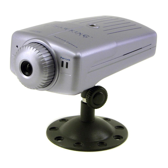
Page 10: Physical Description
Dummy. Please refer to the “Web Configuration” section for detailed information and usage. Link LED The “Link” LED is located on the far right side of the network camera’s lens (when facing the network camera). It is located to the right of the “Power” LED. -
Page 11: Rear Panel
DC Power Connector The DC power input connector is located on the rear panel of the network camera and is labeled DC 5V with a single jack socket to supply power to the camera. Power will be generated when the power supply is connected to a wall outlet. -
Page 12: Top Panel
Screw Hole Located on the top panel of the network camera, the screw hole is used to connect the camera stand onto the camera by attaching the screw head on the camera stand into the screw hole of the camera. -
Page 13: Hnc320W
Link LED The “Link” LED is located on the far right side of the network camera’s lens (when facing the wireless network camera). It is located to the right of the “Power” LED. A steady orange light confirms a good connection. Depending on the data traffic, the LED will begin to flash to indicate that the camera is receiving/transmitting from/to the network. -
Page 14: Rear Panel
DC Power Connector The DC power input connector is located on the rear panel of the wireless network camera and is labeled DC 5V with a single jack socket to supply power to the camera. Power will be generated when the power supply is connected to a wall outlet. -
Page 15: Top Panel
Top Panel Screw Hole Screw Hole Located on the top panel of the wireless camera, the screw hole is used to connect the camera stand onto the camera by attaching the screw head on the camera stand into the screw hole of the wireless camera. Bottom Panel Screw Hole Screw Hole... -
Page 16: Unpacking The Camera
Connecting the HNC300/HNC320W to the Camera Stand The HNC300 and HNC320W packages include a camera stand (installation is optional) with a swivel ball screw head that can be attached to the camera’s screw holes. Attach the camera stand to the camera and orient it in the most appropriate position for your specific application. -
Page 17: Hardware Installation
This section describes the hardware installation procedures for the HNC300 and HNC320W. HNC300 Connect an Ethernet Cable Connect an Ethernet cable to the Ethernet cable port located on the rear panel of the camera, and attach the other end to the network. -
Page 18: Hnc320W
HNC320W Attach Wireless Antenna On the rear panel of the wireless camera, screw into the antenna connector the single external antenna that was included in the product packaging. Connect an Ethernet Cable Connect an Ethernet cable to the Ethernet cable port located on the rear panel of the camera, and attach the other end to... -
Page 19: Attach The External Power Adapter
Attach the External Power Supply Attach the external power supply to the DC power input connector located on the rear panel of the camera. The input connector is labeled “DC 5V”. Connect it to your local power supply. Note: Confirm that the device is receiving power by making sure that the “Power” LED is illuminated. -
Page 20: Security
Note: When the HNC300 or HNC320W is used for the first time, it is highly recommended that the administrator set the "Admin ID" and "Admin Password" to restrict users’ access to the cameras since the Default settings are the Null String (i.e., the default Admin ID and Admin Password are blank). -
Page 21: Software Installation
HNC300 and HNC320W. Web Configuration The HNC300 and HNC320W must be configured via their built-in Web-based Configuration. Knowledge of local area networks (LANs) will be useful when setting up the cameras. In the web browser, enter the default IP address to access the Welcome screen of the network camera. From here you can configure your network camera. -
Page 22: System Administration
System Administration Click on “System Administration” on the “Welcome” screen to access the settings for the network camera. There will be several options to choose from in the menu bar. They are listed below for both, the HNC300 and HNC320W. HNC300... - Page 23 The default setting for the Camera Name is CS-xxxxxx, where “xxxxxx” is the last six digits of the MAC Address. The maximum length is 32 characters (Printable ASCII). Location: This field is used for entering a descriptive name for the location of the network camera.
- Page 24 ISP PPPoE account, click on the “PPPoE” option and enter the Service Name, User ID and Password into the respective fields. The network camera will get an IP address from the ISP each time the Internet Camera starts DNS IP Address: A DNS (Domain Name System) server is an Internet service that translates domain names into IP addresses.
- Page 25 Note: This is a built-in function to add extra capabilities to the network camera. The three options allow the Administrator to configure and camouflage the illumination of the LED indicator. In “Normal” mode, the LED indicator functions as normal. Under “Off”...
- Page 26 Port 85 map to 192.168.0.105 The “Transfer Image” field allows you to open a second port for the network camera to transfer images. The default, Port 8481, is open for image transfer and you can define a second port similar to the above.
-
Page 27: Hnc320W
HNC320W The System menu contains commands for settings for key details that are required for the wireless network camera’s setup. Click on "System" in the system administration menu bar and the System screen will appear as illustrated on the following page. - Page 28 “RARP”, “BOOTP” or “DHCP”. Under this setting, the wireless network camera will automatically assign an IP address from RARP, BOOTP or the DHCP server. Each time the wireless network camera starts up, be sure the RARP, BOOTP or DHCP server is set up to assign a static IP to your wireless network camera.
- Page 29 ANY access point under the infrastructure network mode. To connect the wireless network camera to a specific access point on the network, make sure to set the ESS-ID of the wireless network camera to correspond with the ESS-ID of the access point for communication. Type any string up to 32 characters long (spaces, symbols, and punctuation are not allowed) in the Network Name box.
- Page 30 ‘31323334353637383930313233’. This is the same as the 128-bit ASCII input of ‘1234567890123’. These character counts result in bit counts of 40 and 104, respectively; the wireless network camera will automatically pad your input to a bit count of 64 or 128.
- Page 31 Note: This is a built-in function to add extra capabilities to the network camera. The three options allow the Administrator to configure and camouflage the illumination of the LED indicator. In “Normal” mode, the LED indicator functions as normal. Under “Off”...
-
Page 32: Image
After making sure that al l settings in the System are correct, click on the “Save” button to store the settings for the ireless network camera. You can alternatively click on the “Cancel” button to restore all settings to the values last saved t o or retrieved from the wireless network camera. -
Page 33: Users
Note: 50 Hz and 60 Hz variants are available to accommodate the different light frequencies found in the USA (60 Hz) and Europe (50 Hz). This is to ensure better image quality for the HNC300 and HNC320W. Save/Cancel: After making sure all settings in the “Image” section are correct, click on the “Save” button to store the settings ireless network camera. -
Page 34: Date/Time
“Synchronized with Time Server” or “Set Manually”. Click on “D ateTime” in the System Administration menu bar and the DateTime screen will appear as illustrated on the llowing page: th is 8 characters (Printable ASCII). Important Information nts for the HNC300/HNC320W. This the DateTime menu bar:... - Page 35 DateTime: elect “Synchronized with Time Server” and the time will be based on the GMT (Greenwich Mean Time) setting. The me will be synchronized every 10 minutes. This is also the default setting for the HNC300/HNC320W. P Address: nter the IP Address of the Time...
-
Page 36: Email (Hnc320W Only)
After making sure all of the settings in the System are correct, click on the “Save” button to store the settings for the wireless network camera. You can alternately click on the “Cancel” button to restore all settings to the values or retrieved from the Wireless Internet Camera. - Page 37 On the Upload page, there are three options to choose from: FTP Server, Time Schedule and Manual Operation. FTP Server: There are six basic settings for your FTP server. Host Address: The IP Address of the target FTP server. Port Number: The standard port number for the FTP server is Port 21, and it is also the default setting. If the FTP server uses a specific port, please confirm this with the IT manager.
-
Page 38: Information
“Information” in the system administration menu bar and the Information screen will appear, as illus below: he Information table provides detailed information about the HNC300/HNC320W, such as the Model Name, Firmware sio , Mac Address, and IP Address. -
Page 39: Tools
The Reset com mand restarts the network camera; all saved settings are retained. The Reset panel contains the message “Do you really want to reset this device?”, and a “YES” button. If you do not want to reset the camera, exit the panel without clicking “YES”. -
Page 40: View Image - Activex Mode
View Image - ActiveX Mode To view video images from the web browser, click on “View Image – Activ he video images from Internet Explorer, as illustrated below: Camera Name* - The Camera name will be display when the Camera Name field is entered in the Web Configuration setting under “System”... -
Page 41: View Image - Java Mode
View Image – Java Mode Click on “View Image – Java Mode” from the Welcome screen to access the video images from the Internet Explorer or Netscape browser as illustrated below: ideo server Name* - The Video server name will be display when the Video server Name field is entered in the Web Configuration setting under “System”... -
Page 42: Camera Applications
The HNC300/HNC320W can be utillzed in wide variety of applications. The cameras are all-in-one devices and can be ttached directly to an Ethernet or Fast Ethernet network. The HNC320W also supports the IEEE 802.11b standard. The cameras are standalone systems with built-in CPUs, along with web-based solutions that allow the devices to transmit high quality video images for monitorin om any PC over the Intranet or Internet via a web browser. -
Page 43: Soho (Small Office, Home Office) Applications
SOHO (Small Office, Home Office) Applications SOHO... -
Page 44: Ipview Se Application Installation
Installation Insert the CD-ROM into the CD-ROM drive to initiate the auto-run program. Once completed, a menu screen will ppear as follows:... - Page 45 To install the IPView SE application, click on “Install IPView Software" to activate the installation procedure for the pplication program. nce executed, a p rompt will appear and request the input of the desired language selection. Make the desired selection nd click on “OK”...
- Page 46 The License Agreement prompt will appear, as below. Read the details carefully and click on the “Yes” button to continue with the installation procedure. A prompt will appear and in the Destination Location dialog box, you may click on “Next” to accept the recommended estination location or click on “Browse”...
- Page 47 The Select Program Folder prompt will appear, providing information on where the IPView SE application will be located. Click on “Next” to continue. If you wish to modify your settings, click on “Back” to return to the previous creens. Please wait until one of the two dialog boxes appears, and then select “Yes, I want to restart my computer now” and click on the “Finish”...
- Page 48 Or click on the “Finish” button to complete the installation procedure. fter successfully installing the IPView SE software application, the application program for the HNC300/HNC320W is automatically installed to \Programs\Files Directory. o start running IPView SE, click on Start Menu/Programs/IPView SE /IPView SE.
-
Page 49: Ipview Se - Getting Started
Scan – Searches for all network cameras available on the LAN. (At minimum, this function will locate any Hawking c ameras that have the code “HCVT” located beneath the UPC code on the product packaging or within... -
Page 50: How To Add Camera
How to Add a Camera Add Camera Add Camera lick on Add Camera icon to add a new camera. An Add Camera dialog box will appear, as illustrated below. You ca n enter the IP Address of the camera in the specified field and click the “Add” icon to add a new camera. Note 1: 1. - Page 51 3. At the same time, the Gateway IP address can be replaced by URL as below: . If you incorrectly input the IP Address y ou wish to add, a dialog box will appear to notify you of the error. f you are unsure of the camera’s IP address, you can click on the “Browse”...
- Page 52 If the Login Camera dialog box appears, make sure to enter the correct User “ OK” button and the camera will be added into IPView SE in list format. If the User Name and Password are entered correctly, the camera will not be added into IPView SE. he above dialog box will appear only if the onfiguration setting.
-
Page 53: How To Change Cameras
Camera Config Motion record Assign IP Address to Camera Schedule record Connect / Disconnect Manual record Erase Extera Information ow to Change Cameras Assign IP of New Camera ype in a new IP address. This will connect to the new camera. -
Page 54: How To Connect/Disconnect The Image
Color setting – Adjusts the color setting of the image. View list – Checks the network camera’s event list. Snapshot – Commands the network camera to take a snapshot picture. Rotate image – Rotates the image of the network camera. -
Page 55: How To Delete A Camera
Disconnect the Image – Click on the “Connect/Disconnect button again to disconnect the camera. ow to Delete a Camera Erase Camera – To delete a camera, you must select the camera to delete from the IPView SE control panel. Then click on the “Erase Camera” button. After deleting, the IPVie w SE control panel will appear as below. -
Page 56: Extera Information
Extera Information Extera Information – Lists camera information. ow to Adjust the Property Setting System Configure – The dialog box below will appear. Log Storage: 1. Single HDD Reserve Space: The “Single HDD Reserve Space” permits reserved space by memory size from 500 MB to 1000 MB. - Page 57 2. Split Recording F From the “Split Recording File” you can adjust the file size for recording the video images. (The default size for file size recording is 5MB). If the recorded video files reach the file size, video images will be recorded into other file automatically.
- Page 58 Motion Setting – Adjusts the sensitivity level and selects the Invoke Alarm options to work with the motion detection function (if available). Along with Alarm Beep, the Send Email function can also be enabled when motion is detected. The user can define the time interval to send emails.
- Page 59 Update Firmware Click on the “Update” button and enter the File Path. The firmware will then be updated automatically. you are unsure of the File path, y ou can click on the “Browse” icon. The Browse dialog box will appear with a blank creen, as illustrated below.
-
Page 60: How To Adjust The Recording Setting
ow to Adjust the Recording Setting There are three ways to start recording the image: Motion Record, Schedule Record & Manual Record. Motion Record – Recording is triggered when motion is detected (if the motion detection feature is available). You can adjust the sensitivity level and choose the warning options when motion is detected from the motion setting. -
Page 61: Appendix
: What is the maximum number of users that can be allowed to access the HNC300/HNC320W simultaneously? A: The m aximum number of users that can log onto the HNC300/HNC320W at the same time is 64. Please keep in mind that th overall performance of the transmission speed w ill slow down when many users are logged on simultaneously. -
Page 62: Ping Your Ip Address
Q: Can the HNC300/HNC320W be setup as a PC camera on the computer? : No, the HNC300/HNC320W is an Internet/Network Camera and can only be used on Ethernet and Fast Ethernet etworks. The HNC320W can also be used in wireless networks. - Page 63 If the network camera is situated on a different subnet than your workstation, you will not be able to set the IP address from this workstation. To verify, make sure the first three sections of the IP address of the network camera correspond to the first three sections of the workstation.
-
Page 64: Upgrade Firmware
Q: Noisy images occur. What can I do to fix this? A1: The video images might be noisy if the HNC300/HNC320W is used in a very low light environment. To resolve this issue, place the camera in a location with better lighting. -
Page 65: Time Zone Table
E. Time Zone Table... -
Page 66: Xplug Control Installation
From the Web Configuration menu, select “System” and under the “Loading ActiveX From” input web server location (http://www.web server location.com/ nce the settings are completed the user now is able to access the network camera from the web browser by selecting the age view – ActiveX mode. It must be... - Page 67 Installation To Local PC sert the CD-ROM into the CD-ROM drive to initiated the auto-run program. Once completed, a menu screen will ppear, as follows: To insta ll the Xplug Control, click on the "Inst all X Plug" button to activate the installation procedure for the plug-in rogram Once executed, a prompt will appear and request the input of the desired language selection.
- Page 68 Read the details carefully and click on the “Yes ” button to continue ith the installation procedure. Click on the “Finish” button to complete the setup of the Xplug Control Utility program for the network camera.
-
Page 69: Adjusting The Camera Focus
G. Adjusting the Camera Focus The HNC300/HNC320W features an exchangeable CS-type lens that can be used for different applications as necessary. It supports rotational focus control so the lens can be adjusted to focus under normal and stable conditions to maximize the image quality of the camera. -
Page 70: Specifications: Hnc300
H. Specifications HNC300 Video Specifications Resolution: 640 x 480 pixel Sensor: 1/3” color CMOS sensor Gain control: Automatic Exposure: Automatic White Balance: Automatic Shutter: Electronics 1/60 ~ 1/15000 sec Minimum Illumination: 2.5 lux@f1.4, 3000K color ocal Length: 6.0 mm perture: F=1.8 Signal/ Noise ratio 57dB... - Page 71 Browser Support System requirements: Pentium II, 266 MHz or above Memory Size: 32 MB (64 MB recommended) VGA card reso lution: 800x600 or above Inter net xplore 5.0 or above (ActiveX & ages with other OS) Netsca e p 6.0 or bove (J AVA Mode IPView SE Appli cation...
-
Page 72: Hnc320W
HNC320W Video specification Resolut ion: 640 x 480 pixel Sensor: 1/3” color CMOS s Gain control: Automatic Exp u os re: Automatic White B alance: Automatic Shutter: Electronics 1/60 ~ 1/15000 s Minimum llumination: 2.5lux@f1.4, 3000K color Focal Length: 6.0 mm Aperture: F=1.8... - Page 73 Browser Support ystem requirements: CPU: Pentium II, 266 MHz or above ory ize: 32 MB (64 MB re GA ca resol ion: 800x600 or above Inte rnet xplor 5.0 or above (Act Images fo r other S) Netscape 6.0 or above (JAVA Mode - View Image) IPView SE Appli cation Supported OS: Win 98 SE, Win 2000, Win ME, Win XP...
-
Page 74: How To View Your Camera Via The Internet
I. How to View Your Camera via the Internet The step s outlined below will he lp you install your camera behin Camera Identification Open the camera’s web page by typing its IP address in your web browser, and click on “System Administration”. - Page 75 This will permit users’ routers to support multiple network cameras. By default, Port 80 (on the router) is always open for network camera web server access. For each additional camera that you intend to install, to enable remote viewing, you will need to select the “Open Second Port” option and assign “Web Server” AND “Transfer Image”...
- Page 76 After making sure that all settings in the “System” section are correct, click on the “Save” button to store the settings for the network camera. You can alternatively click on the “Cancel” button to restore all settings to the values last saved to or retrieved from the network camera.
- Page 77 address when enabling your camera to be viewed over the Internet. To view your camera remotely via the Internet, it is recommended (but not required) that you assign a static IP address to your router. You will need to contact your ISP to obtain a static IP address. When the camera is attached to the router, the static IP address will allow you to view the camera over the Internet.
- Page 78 In the “Port Number” field, enter “Port 80 to Port 80” if you intend to you use the camera’s default port settings (discussed earlier in this Appendix). If you do not intend to use the default settings, or if you will be using multiple cameras, you will need to enter a different port number (i.e., 83, 84, etc.).
-
Page 79: Glossary Of Terms
J. Glossary of Terms Numbers 10BASE-T 10BASE-T is (10Mbps) Ethernet over UTP Category III,IV, or V unshielded twisted-pair media. 100BASE-TX The two-pair twisted-media implementation of 100BASE-T is called 100BASE-TX (100Mbps Fast Ethernet). 802.11b An IEEE standard for wireless local area networks. It offers transmissio Mbps in the 2.4-GHz band. - Page 80 DHCP Dynamic Host Configuration Protocol was developed by Microsoft and is a protocol for assigning dynamic IP addresses to devices on a network. With dynamic addressing, a device can have a different IP address every time it connects to the network. In some systems, the device's IP address can even change while it is still connected.
- Page 81 Group Groups consist of several user machines that have similar characteristics, such as being in the same department. Short for hexadecimal, “HEX” refers to the base-16 number system, which consists of 16 unique symbols: the numbers 0 to 9 and the letters A through F. For example, the decimal number 15 is represented as F in the hexadecimal numbering system.
- Page 82 JAVA Java is a programming language that is specially designed for writing programs that can be safely downloaded to your computer through the Internet without the fear of viruses. It is an object- oriented multi-thread programming best for creating applets and applications for the Internet, Intranet and other complex, distributed networks.
- Page 83 Protocol Communication on the network is governed by sets of rules called protocols. Protocols provide the guidelines devices use to communicate with each other, and thus they have different functions. transferred from file server memory to the file server’s network adapter. Others are respons for filtering information between networks and forwarding data to its destination.
- Page 84 Transceiv A transceiver joins two network segments together. Transceivers can also be used to join a segment that uses one medium to a segment that uses a different medium. On a 10BASE-5 network, the transceiver connects the network adapter or other network device to the medium. Transceivers also can be used on 10BASE-2 or 10BASE-T networks to attach devices with AUI ports.