Table of Contents
Advertisement
Quick Links
Advertisement
Table of Contents

Related Manuals for Hawking HomeRemote HRNC1


Summary of Contents for Hawking HomeRemote HRNC1
- Page 2 (1) year from the date of purchase. If the product proves defective during this one-year warranty period, call Hawking Customer Service in order to obtain a Return Authorization number. Warranty is for repair or replacement only. Hawking Technology does not issue any refunds.
-
Page 3: Table Of Contents
Table of Contents Table of Contents ... 3 1 - Introduction ... 5 2 - Package Contents ... 6 3 - System Requirements ... 7 4 - Hardware Installation ... 8 4.1 LEDs and Focusing ... 8 4.2 Camera Ports ... 8 4.2 Camera Ports ... - Page 4 7.2 Camera Buttons ... 38 7.3 Camera Status ... 38 7.4 Control Buttons ... 39 7.5 Video Recording ... 40 7.6 Change Resolution ... 41 7.7 View Four Cameras Simultaneously ... 42 7.8 Viewer Utility Setting ... 43 7.8.1 Setting ... 43 7.8.2 Recording ...
-
Page 5: Introduction
1 - Introduction Thank you for purchasing the HRNC1. The HomeRemote Wireless Video Camera is a high performance, easy-to- install camera that makes monitoring and security a reality for every home. The HRNC1 uses the latest in WiFi wireless networking technology and connects directly to your network, thereby allowing you to access the video from any computer on the network, as well as from anywhere in the world via the Internet or your cell phone. -
Page 6: Package Contents
2 - Package Contents Unpack and Inspect Open the package and carefully remove all items. The complete HRNC1 package consists of: • One HomeRemote HRNC1 Wireless Video Camera • One CD with Easy-Installation Quick Setup Wizard and Utilities • One Quick Installation Guide •... -
Page 7: System Requirements
3 - System Requirements / What is Needed to Get Started The system requirements for PC or Notebook PC users to access the HRNC1 are: • OS System: Windows 98SE, ME, NT, 2000, XP, Server 2003, Vista • CPU: Intel Pentium III 750MHz or above, or Intel Celeron 1GHz or above •... -
Page 8: Hardware Installation
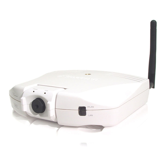
4 - Hardware Installation 4.1 LEDs and Focusing The camera head and its focus ring allow you to modify the aim and focus of the camera. To adjust the camera’s focus, rotate the black focus ring in either direction until the desired viewing area or object becomes sharp/clear. There are four LEDs that indicate camera and network status: Power The LED will be lit orange when the device is powered on and ready for access. -
Page 9: Camera Ports
4.2 Camera Ports The back panel of the network camera includes three ports and a Reset button. Antenna Connector This is a standard Reverse-SMA connector. Any antenna with a Reverse-SMA connector can be connected to the network camera. Power The “Power” port is where you will connect the network camera’s power adapter. The LAN port is where you will connect the Ethernet network cable. -
Page 10: Installation Procedure
4.3 Installation Procedure 1. Unpack all of the contents from the network camera’s package and verify that all the items listed in the “Package Contents” chapter have been included. 2. Locate the antenna connector on the left side of the camera’s rear panel. Screw the base of the antenna (included with the HRNC1) into the antenna connector. -
Page 11: Software Installation
5 - Software Installation Insert the CD that was included in the network camera’s package into your CD-ROM drive. The Auto-load window should appear automatically, as below. If the program does not execute automatically, you can run the “Autorun.exe” program manually from the “Autorun” folder on the CD. You can locate this file on the CD by going to “My Computer” and clicking on the icon for your CD-ROM drive. - Page 12 3. After clicking on the “Admin Utility (Optional), the InstallShield Wizard will begin the installation process. Click “Next” to continue with the installation. 4. If you wish to install the software program in a different location than the one that appears in the window below, click “Change”;...
- Page 13 5. Click “Install” to begin installing the program. 6. The system will install the program automatically.
- Page 14 7. Click “Finish” to complete the software installation. 8. When the installation is completed, the system will auto-run the “Administrator Utility”. On the first page, the cameras that can be found on the network are listed on the left side of the window. Select the one you would like to configure and click “Detail Setting”...
- Page 15 9. After clicking on “Detail Setting” (see figure on previous page), you will be prompted to enter the camera’s name and password. Please enter the default password of “1234”, and click “OK” to log in to the IP setup page. The Admin utility allows users to search for and set up the video cameras located on their networks.
-
Page 16: 6- Using The Administrator's Utility
6- Using the Administrator’s Utility 6.1 General Settings Auto Discover Camera List Click this button to have the Admin Utility search for and automatically discover available cameras within the network. The camera list displays the camera name and setup status for each camera. - Page 17 Internet Click “Add” and a window will appear for you to enter the IP Address of the camera that is available on the network. Delete Click “Delete” to delete the camera from the list. Camera List This list displays the camera name and its connection status. available on the Internet.
-
Page 18: Detailed Settings
6.2 Detailed Settings When you click on the “Detail Setting” button, a window will pop up for you to enter the “Admin Name” and “Password”. The default values are as follows: Name: “Admin”, Password: “1234”. If you have already changed the password (in the Quick Setup Wizard, for example), then enter the new one in the “Password”... -
Page 19: Network Setting
6.2.1 Network Setting Network Settings Video Camera Name IP Address Subnet Mask Gateway DNS Server The default camera name is “HomeRemote Wireless Video Camera”. If you have not already done so, it is recommended that you give the camera a name that will be easy to remember, such as by room in your house, application, etc. - Page 20 Network Setting Video Port The Video Port is used to transmit or receive the streaming video over the network. The default port setting is “5000”. If you want to view the video from the camera, the port setting must be correct. Web Port This camera supports web connection.
-
Page 21: Wireless Settings
6.2.2 Wireless Settings If you want to use the video camera wirelessly, please set it up using a wired Ethernet connection first and make sure your wireless LAN settings are correct. After configuring the wireless LAN settings, you can unplug the Ethernet cable and begin using the camera via the wireless LAN. - Page 22 Wireless Setting Wireless Setting Enable or disable the network camera’s wireless function. By default, the function is disabled. Available Network Available Networks This list shows all available wireless networks within your network camera’s accessible range. It also displays the important information from these networks, including the SSID and Signal Strength.
- Page 23 Profile List Profile List The “Profile List” allows you to manage the networks you connect to frequently. The profile list displays all the profiles and their corresponding settings, including Profile Name, SSID, Channel, etc. If you want to connect to any of the profiles on the list, double-click the profile or select the profile and click “Activate”.
- Page 24 Configure the Profile Authentication Type Allows you to select between “None”, “Open System”, “Shared Key”, and “WPA-PSK”. Encryption Type Select the type of encryption that your wireless network is using. If you are unsure about the type of encryption your wireless network is using, you can refer to your router’s settings for details.
-
Page 25: Email Settings
6.2.3 Email Settings E-Mail Setting Recipient Email Address SMTP Server Sender E-mail Address SMTP Authentication PLEASE NOTE: Some SMTP servers require authentication via an account name (or user name) and password. You can check this in Microsoft Outlook, for example, by clicking on the “Tools” tab on the top of your Outlook page. -
Page 26: Motion Detection
6.2.4 Motion Detection The HRNC1 features built-in motion detection with snapshot emailing. In order to utilize this feature, you will have to enable it either in the “Network Settings” section of the camera’s web UI, or in the “Motion Detection” section of the Administrator Utility, as shown in the figure below. -
Page 27: Mobileview
6.25 MobileView The MobileView feature allows the user to isolate the video frame on its own page. Please note that this page will only show a still image of the video frame. The user can click on the web browser’s “Refresh” button to update the image. This can be useful when trying to access quick snapshots from the HRNC1 from a cell phone. -
Page 28: Ntp Settings
6.2.6 NTP Settings The user can enable the NTP (Network Time Protocol) function by clicking on the “Enable” radio button. By activating this function, you can sync the camera’s clock with one of the time servers provided in the “NTP Server” scroll-down menu. -
Page 29: Resolution
6.2.7 Resolution Resolution Resolution Select the desired video resolution format. Keep in mind that larger resolution requires more bandwidth. 640 x 480 is “VGA” format. 320 x 240 is “CIF” format. 160 x 120 is “QCIF” format. -
Page 30: Advanced Settings
6.2.8 Advanced Settings Advanced Setting UPnP What is DDNS? Enable/Disable Provider Domain Name Account Password When the UPnP function is enabled, the camera can be detected by a UPnP compliant system such as Windows XP. The camera will be displayed in Network Neighborhood, within Windows XP, so you can click on the camera directly to view the video through the web browser. -
Page 31: Users
6.2.9 Users Password Current Password New Password Confirm New Password Enter the user’s current password. Enter the new password you want to use for this user. Retype the new password to confirm the setting. -
Page 32: Tools
6.2.10 Tools Tools Firmware Version Firmware Update Reset to Default LED Light Off Displays the current version of the firmware. Users cannot use the Admin utility to upgrade the firmware in this version of the utility. Please upgrade the firmware via the web user interface. -
Page 33: About
6.2.11 About About Administrator Utility Version Displays the current version of the Administrator Utility. -
Page 34: Setting Wizard
6.3 Setting Wizard When you click the “Setting Wizard”, a screen will pop up for you to enter the “Administrator Name” and “Password”. The default value is as follows. Name: “Admin” Password: “1234” If the name and password you enter are correct, you can start to setup the camera. - Page 35 Setting Wizard Video Camera Name IP Address Subnet Mask Gateway Video Port Cancel Finish When you finish with the camera settings, you can click “Ok” to run the “Camera Viewer” (i.e. recording software) immediately or click “Cancel” to run the “Camera Viewer” later. The default camera name is “HomeRemote Wireless Video Camera”.
-
Page 36: Camera Viewer (Recording Software) Utility
7 – Camera Viewer (Recording Software) Utility The Camera Viewer (Recording Software) Utility allows users to simultaneously access and view video from up to four cameras. It also allows users to record video manually or by schedule, and playback recorded files. Certain status items for the selected camera, such as frame rate, video received, etc. -
Page 38: Camera Buttons
7.2 Camera Buttons Camera Buttons Camera 7.3 Camera Status The status bar will be shown in one of four different colors to indicate the status of each connected camera. Camera Status Yellow Blue Pink If you click on one of these four camera buttons, the Viewer Utility will connect to the selected camera that you want to view and configure. -
Page 39: Control Buttons
7.4 Control Buttons Stop Control Buttons Play Stop Pause Forward Snapshot Record Pause Snapshot Record Play Forward The Play button is an intelligent play user interface. In the normal display mode, if the camera is disconnected, clicking on the Play will make the viewer connect to the camera. -
Page 40: Video Recording
7.5 Video Recording This utility allows you to record video files in AVI format. There are two ways to record video: a. Manual Recording, and b. Schedule Recording. Manual Recording You can manually record the video stream into an assigned video file. Click “Record”, and the “Record to Disk”... -
Page 41: Change Resolution
7.6 Change Resolution The camera viewer supports two resolution formats: a. 640 x 480 (VGA), and b. 320 x 240 (CIF). You can change the resolution of each connected network camera by clicking on the Resolution button. Note: Before changing the network camera’s resolution, you have to select the camera by first clicking on its corresponding camera button. -
Page 42: View Four Cameras Simultaneously
7.7 View Four Cameras Simultaneously Clicking on the four-division button will allow you to view up to four cameras simultaneously in a four-division window. -
Page 43: Viewer Utility Setting
7.8 Viewer Utility Setting Click the Setting button . The camera’s setting window will then appear. Note: When you want to change settings such as the IP Address, Video Port, etc. in the “Setting” option, you must first disconnect the camera by clicking the Stop button. 7.8.1 Setting Setting Name... -
Page 44: Recording
7.8.2 Recording You can set up the schedule for recording here. This utility will automatically record the video stream in the assigned file folder according to the schedule. The recorded video files will be in AVI format. Note: 1. The utility will only start to record the video stream when this utility is running and is successfully connecting to the camera at the beginning of the schedule. - Page 45 Schedule Cycle Recording Select this item to enable cycle recording. When Cycle Recording is enabled and the storage usage has already reached the maximum reserve storage space, the utility will automatically delete the oldest recorded video file and use the space to store newly recorded video streams. One-Time Schedule You can assign a range of time and the utility will automatically record the video stream during the specified period of time only.
-
Page 46: Status
7.8.3 Status You can see the current status information of the connection session between the utility and the Video Camera. Status Connected Stream Started At Time Elapsed Video Received Frame Rate Data Rate Number of Frames Displays “Yes” when the utility is connected to the video camera and displays “No”... -
Page 47: General
7.8.4 General You can manage storage usage for this Video Camera here. General Snap Shot Directory Record Directory Free Disk Space Max Recording Space Used Disk Space Max Video File Size This lets you assign the directory where bitmap files will be stored when you click the “Snapshot”... -
Page 48: About
7.8.5 About About Camera Viewer Utility Version 7.9 Playback Click the “Open File” and a “Load File” window will appear. Select the file that you would like to play. Displays the current version of the Camera Viewer Utility. - Page 49 The viewer will begin playing the selected video file. Playing Control Play Pause Stop Forward When the video playback is in the Stop state, click Play and the viewer will play the video file from the starting point. playback is in the Pause state, click Play and the viewer will play the video file from the current pause point.
-
Page 50: Rotate Video
7.10 Rotate Video The Rotate function allows you to rotate the video frame 90 degrees counterclockwise each time you click the “Rotate” button . With this function, you can view live video at normal, 90-degree, 180-degree and 270-degree angles. Below is a screenshot of video playing at a 90-degree counterclockwise angle. -
Page 51: Web Connection And Setup
8 - Web Connection and Setup When the camera is connected, the video image will display directly on the homepage. The menu options for the web control screen are as follows: Camera View: View live video and adjust the video format from the menu. Network Settings: Configure the camera functions from the menu. -
Page 52: Camera Settings
8.1 Camera Settings Camera Setting Flip Digital Zoom Frequency Resolution Day/Time Format Snapshot & Mail Apply Click on “Apply” to flip the image. This feature if useful if you decide to mount the camera upside-down. This allows you to zoom the video size in or out. Click “x2” and the image size in the display area will be magnified to two times the original size. -
Page 53: Network Settings
8.2 Network Settings Network Settings (1) - Page 54 Network Settings (2, continued)
- Page 55 Network Settings (3, continued) Network Settings (4, continued)
- Page 56 Change Admin Password Current Password New Password Confirm Password Apply Change Email Account Email Address SMTP Server Sender E-mail Address SMTP Authentication Recipient Email Address Apply PLEASE NOTE: Some SMTP servers require authentication via an account name (or user name) and password. You can check this in Microsoft Outlook, for example, by clicking on the “Tools”...
- Page 57 The HRNC1 features built-in motion detection with snapshot emailing. In order to utilize this feature, you will have to enable it either here in the “Network Settings” section of the camera’s web UI (as shown in the figure titled “Network Settings (2, continued)” on page 54, or in the “Motion Detection” section of the Administrator Utility.
- Page 58 Change IP Address IP Address Enter an unused IP Address within the IP address range used on your LAN. If the IP Address range of your LAN is between 192.168.1.1 and 192.168.1.254, you can set an unused IP Address from within this range for the camera.
- Page 59 Change Camera Name Camera Name The default camera name is “HRNC1”. It is recommended that you give the camera a name that is easy to remember. Firmware This displays the current firmware version of the camera. Apply When you finish in the “Change Camera Name” section, click “Apply”. Change DDNS Setting DDNS is an acronym for “Dynamic Domain Name Server”.
- Page 60 Change NTP Setting The user can enable the NTP (Network Time Protocol) function by clicking on the “Enable” radio button. By activating this function, you can sync the camera’s clock with one of the time servers provided in the “NTP Server” scroll-down menu. Select the time zone from the “Time Zone”...
- Page 61 Maintenance Load Default To reset the camera to its factory default settings, click “Apply”. Then, follow the instructions on the screen to complete the process. The factory default settings are as follows. Camera Name: “HomeRemote Wireless Video Camera” IP Address: “192.168.1.231” Subnet Mask: 255.255.255.0 Administrator Name: “Admin”;...
-
Page 62: Wireless Settings
8.3 Wireless Settings Wireless Setting Wireless Connection Mode SSID Enables or disables the camera’s wireless function. By default, the function is disabled. Infrastructure: This operation mode requires the presence of a Wireless LAN (WLAN) Access Point or Router. All communication is done via the Access Point or Router. - Page 63 Channel This setting is only available for Ad Hoc mode. Select the number of the radio channel used for the networking. The channel setting should be the same as the network you are connecting to. Site Survey Click the “Site Survey” button to search all the available wireless LAN networks in the vicinity of the video camera.
- Page 64 Site Survey Site Survey List Refresh Button Connect Button Close Button Once you have finished making all the desired changes in the “Wireless Settings” section, be sure to click the “Apply” button to the right of the “Change Wireless Settings” heading. The list displays the information of all the available wireless networks that are in the vicinity of the camera.
-
Page 65: Users
8.4 Users The “User Accounts” section allows users to add four user accounts for users to view video from the Camera Viewer and web user interface. These users, unlike the Administrator, are not allowed to change the camera’s configuration settings. User 1 / 2 / 3 / 4 User Name Password... -
Page 66: Frequently Asked Questions
9 - Frequently Asked Questions Q1: What is an Internet/Network Camera? A: An Internet/Network Camera, like the HRNC1, is a standalone system that connects directly to an Ethernet or Wireless network. A network or Internet camera is different from a conventional PC or web camera in that it is an all-in-one system with built-in CPU and web-server, thereby allowing the user to connect directly to the network. -
Page 67: Technical Specifications
10 - Technical Specifications Video Specifications Max Resolution: 640 x 480 pixels Sensor: 300,000K pixels, 1/4" color CMOS sensor Gain control: Automatic Exposure: Automatic White Balance: Automatic Focal Length: 6.0 mm Aperture: F=1.8 Image (Video Settings) Image compression: Motion-JPEG Image Video Color: Digital 24-bit Color Frame rate: 30+ fps@QCIF, 30fps@CIF, 10fps@VGA Video resolution: 160 x 120, 320x240, 640x480... -
Page 68: Appendix A: How To View Your Camera Via The Internet
11 - Appendix A: How to View your Camera via the Internet To learn how to easily set up your Wireless Video Camera for remote viewing over the Internet, please visit www.hawkingtech.com/hrcamerapf.php and review the tutorial. The tutorial will provide you with easy-to-follow instructions on how to configure your camera within minutes for Internet viewing. - Page 69 2. Click on Setup in the blue bar at the top right-hand side of the homepage. The Setup page will appear, as shown in the figure below. On the Setup page, click on Network Camera Setup.
- Page 70 3. In the Network Camera Setup section, find your camera in the Current Cameras list according to the name and location you have set for it, and then make sure that the IP Address and port number match the ones you set for it in the camera’s Quick Setup Wizard.
-
Page 71: Appendix B: Viewing Via Upnp In Windows Xp
12 - Appendix B: Viewing via UPnP in Windows XP When the UPnP function is enabled, the camera can be detected by a UPnP compliant system such as Windows XP. The camera will be displayed in “My Network Places” in Windows XP, and you can double-click on the camera directly or right-click the camera and select “Invoke”... - Page 72 3. In the “Local Area Connection Properties”, select the “Advanced” option menu and click “Settings”. 4. The “Windows Firewall” screen will appear. Select the “Exceptions” option menu.
- Page 73 5. Enable the “UPnP Framework” from the “Programs and Services list” and click “Ok”.