Table of Contents
Advertisement
Quick Links
Advertisement
Table of Contents

Related Manuals for Honeywell SMX-AUS


Summary of Contents for Honeywell SMX-AUS
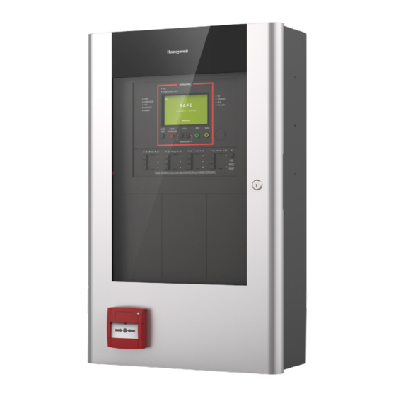
- Page 1 SMX-AUS Fire Alarm Control Panel (FACP) Installation Guide NS-MN-0030 / 11.2020...
- Page 2 Installation Guide SMX-AUS Fire Alarm & Emergency Communication System Limitations While a life safety system may lower insurance rates, it is not a substitute for life and property insurance! An automatic fire alarm system—typically made up of smoke detectors, heat detectors, manual call points, audible warning devices, and a fire alarm control panel (FACP) with remote notification capability—can provide early warning of a developing fire.
- Page 3 Installation Guide SMX-AUS Heat detectors do not sense particles of combustion and alarm only when heat on their sensors increases at a predetermined rate or reaches a predetermined level. Rate-of-rise heat detectors may be subject to reduced sensitivity over time. For this reason, the rate-of-rise feature of each detector should be tested at least once per year by a qualified fire protection specialist.
-
Page 4: Table Of Contents
Software Downloads ............................ 6 Battery Power Supply ..........................24 Documentation Feedback ........................6 The Columns and Their Usage ....................24 Model: SMX-AUS Series Details ........................7 Battery Calculations for 2-loops..................25 Replaceable Chassis Details ........................7 Testing the System ..........................28 Specifications ..............................7 Inspection and Testing ......................28... -
Page 5: About This Guide
However, the manufacturer assumes no responsibility for inaccuracies and reserves the right to modify and revise this document without notice. These instructions cover the programming and commissioning of the SMX-AUS Fire Alarm Control Panels (FACP). For any technical assistance email at HBTPacificFireSupport@Honeywell.com. -
Page 6: Cautions And Warnings
To ensure that you are installing and programming the latest features, we strongly recommend that you download the most current version of software for each product prior to commissioning any system. Contact Technical Support with any questions about software and the appropriate version for a specific application. The Technical Support email is: HBTPacificFireSupport@Honeywell.com. 1.6 Documentation Feedback Your feedback helps us keep our documentation up-to-date and accurate. -
Page 7: Model: Smx-Aus Series Details
Installation Guide SMX-AUS Model: SMX-AUS Series Details Panel Variants (SKU Number) Number of Loops Number of Devices Supported Address Range Sensors: 99 1 - 99 915-200-103 Modules: 99 101 - 199 Total loop devices: 198 Sensors per loop: 99 1 - 99... -
Page 8: Programmable Features/Settings
• Configuration options: USB storage device, mobile app, and the panel interfaces • Non-latched supervisory action for detectors and modules • 10,000 event logs for SMX-AUS • Configurable alarm sensitivity levels for smoke and multi sensors • • View pulse width (PW) values Fire-Trip latching for relays and control modules, until Fire Mode Reset •... -
Page 9: The Main Pcb Layout
Installation Guide SMX-AUS 2.5 The Main PCB Layout The fire alarm control panel has a printed circuit board (PCB), which includes a central processing unit (CPU), ports, LEDs, and other electronic components. The following figure illustrates the panel’s interfaces, which connect with loops, relays, control points, and so on. - Page 10 Installation Guide SMX-AUS Table: Main PCB Interfaces Designator Connection Wire Connections Power limited Designator Connection Wire Connections Power limited Pin1 = NC USB1 Program Relay Pin2 = NO Pin3 = COM USB2 Do not use AUX2 Do not use TCP/IP...
-
Page 11: Power Ratings
Installation Guide SMX-AUS 2.5.1 Power Ratings When mains is disconnected, the maximum current drawn by the panel from the batteries is 0.7 A in the quiescent condition and 6.97 A in the alarm condition. The current value may vary as per the load conditions. - Page 12 Installation Guide SMX-AUS 2. Panel mounting Perform the following steps to mount the panel on the wall as per the surface mounting method: • Hold the panel on to the wall at the position you want to install it. Verify the space available for opening the door of the panel and if the panel is accessible.
- Page 13 Installation Guide SMX-AUS Fig. 5: Removing the Knockouts The hub shall be connected to the conduit before the hub is connected to the enclosure. NS-MN-0030 / 11.2020...
- Page 14 Installation Guide SMX-AUS 3. Install two 26 Ah batteries inside the panel. Recommended battery : AUSCELL 26 Ah. The standby batteries should be in the enclosure as shown in Fig. 6. Allow a sufficient air gap between them (10 mm recommended) to allow for heat dissipation.
- Page 15 Installation Guide SMX-AUS Wiring the batteries • Connect the batteries using the wire (with P18 connector) provided in the panel installation kit. • The battery wiring should be done using the screws for 26 Ah batteries. • It is recommended to connect the DC input first and then connect the main PCBA to the batteries using the cable harness.
-
Page 16: Real-Time Clock With Battery
Installation Guide SMX-AUS • External Power Connection Receives power from an internal power supply unit. For the internal power supply details, refer to Chapter 2.5.1. The external mains supply cable must be terminated at the Mains Termination Block (MTB) located on the bracket. -
Page 17: Loop Wiring Connectors
Installation Guide SMX-AUS 3.3 Loop Wiring connectors The SLC (detector) circuits should be installed as loops with or without isolator modules. The wiring details are as described below. • The detection loop connections are made on terminal blocks at the top of the base card. -
Page 18: Compatible Devices List
Installation Guide SMX-AUS 3.3.1 Compatible Devices List Following are the System Sensor - Classic Loop Interface Protocol (CLIP) devices, that are compatible with the SMX-AUS panel: Table 1: Compatible Devices List Device Description Model Number MANUAL CALL POINTS Addressable Manual Call Point... - Page 19 Installation Guide SMX-AUS Device Description Model Number DETECTOR BASES Addressable Detector Base, System Sensor B501AUS / B501AUS-IV Universal Addressable Detector Base, Pure White, System Sensor B501AUS-W Black Detector Base for addressable detectors, System Sensor B501AUS-BK Short Circuit Isolator Base, Off-White, System Sensor...
-
Page 20: Notification Appliance Circuits (On-Board Nacs)
Installation Guide SMX-AUS 3.4 Notification Appliance Circuits (On-Board NACs) • Notification circuits are supervised, power limited, Class B wires, which may be connected to energy-limited cable. • Only the compatible, Notification Appliances that are listed in Device Compatibility Document are recommended. -
Page 21: Printer Connection
Installation Guide SMX-AUS 3.7 Printer Connection The SMX-AUS panel can connect to a printer, whose options can be configured. The basic steps for the connection and configurations are as follows: 1. Make a custom cable. At the printer side: Connect the cable with a 9-pin D-type RS232 serial connector. -
Page 22: Connecting Power Sources And Outputs
The short test for all terminals is wire-to-wire short directly (Impedance ≤ 0.1 Ohm). 3.9 Earth Ground Impedance The earth fault impedance of each connection at the SMX-AUS panel is wire-to-wire short between the earth ground and connection wire (Impedance < 0.1 Ohm). 3.10 Connecting Power Sources and Outputs •... -
Page 23: Maximum Wiring Impedance
Installation Guide SMX-AUS 3.11 Maximum Wiring Impedance The maximum wiring impedance of each connection at the SMX-AUS panel is as below. Interfaces Wiring Impedance 40 Ω Loop 1 40 Ω Loop 2 6 Ω @1*HRL / 3 Ω @2*HRL / 2 Ω @3*HRL NAC 1 (Special Application) 100 Ω... -
Page 24: Battery Power Supply
Installation Guide SMX-AUS Battery Power Supply The below sample table explains how to calculate the actual load and current consumption. As a sample, in the first row, a Main Circuit Board’s consumption is explained with sample data. 4.1 The Columns and Their Usage The total current value required for a device is derived by entering the number of devices in the Qty (Quantity) column. -
Page 25: Battery Calculations For 2-Loops
Installation Guide SMX-AUS 4.2 Battery Calculations for 2-loops Below table provides a sample sheet for calculating the battery values for 2-loops. You are fully responsible for verifying these calculations. Use the dropdowns and the yellow cells to enter values. Table: Pluto AUS - battery Calcs_V9_Exercises_working... - Page 26 Installation Guide SMX-AUS Standby Current (amps) Secondary Alarm Current (amps) Device Type Current Draw Total Current Draw Total 5251RB-WP Not found 22051E 0,000300 7251 0,000230 TC1700 Not found 2700 Not found TC2700 Not found TC2700TMB Not found TC6500 Not found...
- Page 27 Installation Guide SMX-AUS Table: Pluto AUS 2-loop battery Calculation - Calculation in Total Sheet Required Standby Time in Hours 24 Hours Standby Load Current (Amps) 0,70770 Amps 16,985 Ah Required Alarm Time in Hours 30 Minutes Alarm Load Current (Amps)
-
Page 28: Testing The System
Installation Guide SMX-AUS Testing the System 5.1 Inspection and Testing Inspection and Testing should conform to any national, regional or local standards applicable for the specific installation. Before connecting any field wiring to the panel, the following must be tested: 5. -
Page 29: Maintenance
Installation Guide SMX-AUS Maintenance 6.1 Battery Maintenance When main power is unavailable, the battery can support the panel for 24 hours. Sealed lead-acid batteries must be replaced within 3 years from their date of manufacture. You can get replacement batteries with suitable capacity from the manufacturer. To know the replacement battery capacity, refer the control panel marking label. -
Page 30: Fuse Maintenance
PTC RESET FUSE 30 V / 8 A RADIAL. This is a non-replaceable maintenance-free fuse. 6.3 Kit Assemblies Part Number Description 315-651 Panel Chassis Kit-HON-AUS-2-Loop 315-650 Panel Chassis Kit-HON-AUS-1-Loop 315-652 SMX-AUS SMPS 1 & 2 315-501 Relay Card Kit NS-MN-0030 / 11.2020... -
Page 31: Appendix 1 - Replacing The Panel Chassis
Installation Guide SMX-AUS Appendix 1 - Replacing the Panel Chassis SMX-AUS panels allow you to change the chassis. The replacement process begins with removing the electrical and device connections and ends with connecting them again in the new chassis. 7.1 To change the enclosure 1. -
Page 32: Appendix 2 - Installation Of Relay Card, Da / Da2
Installation Guide SMX-AUS Appendix 2 - Installation of Relay card, DA / DA2 and SDM-4 / SAM-4 Fig. 16: Relay card, DA / DA2 and SDM-4 / SAM-4 NS-MN-0030 / 11.2020... - Page 33 Installation Guide SMX-AUS Fig. 17: Wiring - Relay card to Customer's Brigade Interface Fault Relay (Relay 5) and Battery Discharged Relay (Relay 7) are normally held in an energized state for fail-safe operation. Fault Relay will de-energize under any fault condition.
- Page 34 Installation Guide SMX-AUS Relay Card Mounting: 1. Unlock and open Panel Front & Middle Door. 2. Remove power from the panel remembering that there may be more than one source of power. 3. Fit the supplied standoffs to the CHS-3L and fix Relay card metal mounting plate on it using supplied 2 No.’s screws as shown in figure.
-
Page 35: Appendix 3 - Periodic Testing And Maintenance
Installation Guide SMX-AUS SDM-4 / SAM-4 Card Mounting : 1. Unlock and open Panel Front & Middle Door. 2. Remove power from the panel remembering that there may be more than one source of power. 3. Fit the supplied standoffs to the CHS style mounting plate. - Page 36 HONEYWELL BUILDING TECHNOLOGIES 9 Columbia Way Baulkham Hills, NSW 2153 Tel: Australia - 1300 368 755 HBTPacificFireSupport@honeywell.com E-Mail: Technical changes reserved! www.honeywell.com © 2020 Honeywell International Inc. Website:...