
Related Manuals for Honeywell SILENT KNIGHT SWIFT


Summary of Contents for Honeywell SILENT KNIGHT SWIFT
- Page 1 SWIFT® Smart Wireless Integrated Fire Technology Instruction Manual Document LS10036-000SK-E Rev: G 4/13/2020 ECN: 150692...
- Page 2 Fire Alarm & Emergency Communication System Limitations While a life safety system may lower insurance rates, it is not a substitute for life and property insurance! An automatic fire alarm system—typically made up of smoke Heat detectors do not sense particles of combustion and alarm detectors, heat detectors, manual pull stations, audible warning only when heat on their sensors increases at a predetermined rate devices, and a fire alarm control panel (FACP) with remote notifica-...
- Page 3 Honeywell®, Silent Knight®, and SWIFT® are registered trademarks of Honeywell International Inc. Microsoft® and Windows® are registered trademarks of the Microsoft Corporation. Chrome™ and Google™ are trademarks of Google Inc. Firefox® is a registered trademark of The Mozilla Foundation.
- Page 4 • Your suggestion for how to correct/improve documentation Send email messages to: FireSystems.TechPubs@honeywell.com Please note this email address is for documentation feedback only. If you have any technical issues, please contact Technical Services. SWIFT® Smart Wireless Integrated Fire Technology Manual — P/N LS10036-000SK-E:G 4/13/2020...
-
Page 5: Table Of Contents
Table of Contents Section 1: Overview ................................8 1.1: Purpose ..........................................8 1.2: Assumed Knowledge ......................................8 1.3: Additional References......................................8 1.4: About this Manual......................................8 1.5: About the Mesh Network....................................9 1.6: Abbreviations ........................................9 1.7: Cybersecurity Recommendations ..................................9 Section 2: WSK-WGI Wireless System Gateway ......................10 2.1: Description........................................10 2.2: Agency Approvals......................................10 2.2.1: FCC........................................10... - Page 6 Table of Contents 2.9.8: Overlapping Wireless Sensor Networks and Limitations........................28 2.9.9: Activation of Wireless Output Devices ..............................28 2.9.10: Avoiding RF Interference ...................................28 2.9.11: Trouble Messages ....................................29 Section 3: Wireless Devices ............................30 3.1: Description........................................30 3.2: Agency Approvals......................................31 3.2.1: FCC........................................31 3.2.2: Federal Institute of Telecommunications .............................31 3.3: Specifications........................................32 3.4: Installing, Mounting, and Wiring Devices...............................32 3.4.1: Batteries ........................................32...
- Page 7 Table of Contents B.1.2: RF Scan Test ......................................47 Conduct an RF Scan Test..................................47 Status of an RF Scan Test ..................................47 B.1.3: Retrieving Site Survey Results ................................48 Appendix C: Troubleshooting and Testing........................49 C.1: Troubleshooting ......................................49 C.2: Testing the Gateway and Devices ...................................50 C.2.1: Testing LED Indicators..................................50 C.3: Testing the Wireless Network ..................................50 C.3.1: Network Topology ....................................51...
-
Page 8: Section 1: Overview
Section 1: Overview 1.1 Purpose The SWIFT® Network Manual provides an overview of the following: • Wireless fire alarm system • Instructions for installing and configuring the wireless devices • Information on monitoring the status of the wireless devices • Removal and replacement procedures of the Wireless Gateway •... -
Page 9: About The Mesh Network
Instructions” for more information. Use of these products in combination with non-Honeywell products in a wireless mesh network, or to access, monitor, or control devices in a wireless mesh network via the internet or another external wide area network, may require a separate license from Sipco, LLC. For more information, contact Sipco, LLC or IntusIQ (Ipco), LLC at 8215 Roswell Rd, Building 900, Suite 950. -
Page 10: Section 2: Wsk-Wgi Wireless System Gateway
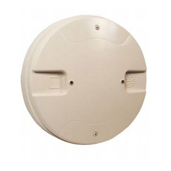
Section 2: WSK-WGI Wireless System Gateway 2.1 Description The WSK-WGI is a device in a wireless fire system that acts as a bridge between fire alarm control panels (FACPs) and wireless fire devices. All wireless fire devices communicate with the gateway over the wireless network formed by the devices and the gateway. The gateway is powered by either the SLC loop or by any external +24VDC UL listed power supply. -
Page 11: 1: Environmental Specifications
Magnetic Sensors WSK-WGI Wireless System Gateway Minimum signal strength level needed at the receiver for a secondary path or Must be 18 dBm higher than the noise primary path with weak link trouble reporting disabled. floor down to a minimum of -80dBm Maximum ambient noise level -85dBm Maximum RF Power Output... -
Page 12: Mounting And Wiring
WSK-WGI Wireless System Gateway Mounting and Wiring 2.7 Mounting and Wiring WARNING: POLYPROPYLENE ELECTRICAL INSULATION MATERIAL ENSURE THAT THE POLYPROPYLENE ELECTRICAL INSULATION MATERIAL COVERING THE PRINTED CIRCUIT BOARD INSIDE THE GATEWAY IS NOT REMOVED OR TAMPERED WHILE INSTALLING OR CLEANING. 2.7.1 Mounting The gateway has two major pieces, the cover and the mounting plate. -
Page 13: 2: Wiring
Mounting and Wiring WSK-WGI Wireless System Gateway locating pin locating pin locating pin Figure 2.4 Attaching Cover to Mounting Plate 2.7.2 Wiring • All wiring must be installed in compliance with the National Electrical Code and the local codes having jurisdiction. •... -
Page 14: 3: Gateway Powered By The Slc
WSK-WGI Wireless System Gateway Mounting and Wiring 2.7.3 Gateway Powered by the SLC To power the gateway using the signaling line circuit, connect the gateway as described in the table and graphic below: Terminal Description Pins A5 and A7 SLC - (Common) & SLC Output + A5 and A6 SLC - (Common) &... -
Page 15: Configuration And Programming
Configuration and Programming WSK-WGI Wireless System Gateway SLC out to next device (Class B) or SLC return to FACP (Class A) SLC in from FACP/device External +24VDC Power Figure 2.7 Wiring Connections: WSK-WGI Powered by an External, Regulated +24VDC Source NOTE: It is recommended to use the same wire gauge if there are multiple connections to the same terminal. -
Page 16: 2: Remove A Profile
WSK-WGI Wireless System Gateway Configuration and Programming Ensure that the Scan On selection box in the Communicator Window is checked. Select the gateway from the Communicator Window on the right side of the Tools screen. Figure 2.9 Gateway Selection 10. Click Assign. Figure 2.10 Assign a Profile The gateway is now included in the list of devices with a profile assigned. -
Page 17: Remove A Profile From A Gateway Without Using Swift Tools
Configuration and Programming WSK-WGI Wireless System Gateway Figure 2.12 Reset Devices Screen The profile is removed and the gateway is reset to factory default state. Refer to Section 3.5.3 on page 33 for information on returning devices to the factory default state. Remove a Profile from a Gateway without using SWIFT Tools Start with the gateway powered off. -
Page 18: 4: Slc Configuration
WSK-WGI Wireless System Gateway Configuration and Programming • The Progress Status column indicates progress status of the selected gateway. • The No. of Devices Joined column indicates the number of devices that are in the mesh network including the gateway. •... -
Page 19: Operations
Operations WSK-WGI Wireless System Gateway NOTE: When a wireless relay, wireless AV base, or wireless sync module is in use, module device count must be limited to 109 modules per loop. This includes wired and wireless modules that are on the same loop. The module address range must be within 1-109. 2.9 Operations 2.9.1 Modes of Operation Mesh... -
Page 20: Initial Mesh Restructuring Mode
To avoid interference, the mesh net- work periodically checks for adjacent mesh networks created by Honeywell. The gateway reports “Normal” to the communicator display of the SWIFT Tools application. - Page 21 Operations WSK-WGI Wireless System Gateway From the Home Screen, select the Site Survey, Create Mesh Network, or Diagnostics function. Click Operations. The following screen is displayed. Figure 2.18 Operations Menu Select Gateway Operations to lock/unlock the gateway. The Lock/Unlock Gateway screen displays the list of gateway/gateways that are in the range of the W-USB adapter connected to your /Laptop.
-
Page 22: Password Reset
2.9.4 Enable/Disable Max Gateway Trouble Reporting This feature is used to determine if the permitted number of Honeywell SWIFT systems that can co-exist in range of each other without reducing overall performance has been exceeded. The default setting is On (enabled). - Page 23 Operations WSK-WGI Wireless System Gateway Perform a link test between each of the four device locations (Mesh 1 to Mesh 5, Mesh 2 to Mesh 5, Mesh 3 to Mesh 5, and Mesh 4 to Mesh 5) using a separate pair of test devices. Refer to Appendix B, “Site Survey” for instructions on how to perform a site survey.
- Page 24 WSK-WGI Wireless System Gateway Operations Export network statistics to Excel for each gateway, and by using the SLC address tab for each edge device, review the primary and secondary parent link strengths for each edge device in each mesh system. In this case, 25 would be the stronger link.
-
Page 25: Disabling Max Gateway Reporting
Operations WSK-WGI Wireless System Gateway NOTE: If the mesh networks are installed vertically in a high-rise building or horizontally in adjacent buildings, the evaluation in steps 4-11 only needs to be performed on the mesh edge devices between different meshes on adjacent floors. horizontal- adjacent buildings Note: Additional mesh networks can be installed in adjacent buildings/stories in the high-rise (beyond... -
Page 26: 5: Weak Link Trouble Reporting
WSK-WGI Wireless System Gateway Operations 2.9.5 Weak Link Trouble Reporting The SWIFT Network uses two paths of communication for each device. To establish the link between devices as a viable communication path, the signal strengths must meet the limits provided in Section 2.3. The SWIFT Network implements a higher threshold for primary connections to provide an extra layer of robustness and immunity from interference. -
Page 27: 7: Silence Network Command
Operations WSK-WGI Wireless System Gateway Launch the SWIFT Tools application. Refer to Appendix A, “SWIFT Tools” for more information about the programming utility. From the Home Screen, select the Diagnostics function. Select a Gateway from the communicator panel. Click View Mesh. SWIFT Tools will display Lock/Unlock option. Refer to Section 2.9.3 on page 20 for additional information. Click Advanced Functions on top of the mesh display. -
Page 28: 8: Overlapping Wireless Sensor Networks And Limitations
2.9.8 Overlapping Wireless Sensor Networks and Limitations The SWIFT Network technology shares the RF spectrum with other Honeywell Fire Wireless Sensor Network systems. Honeywell Fire has generally established a limit of 4 overlapping networks (4 gateways maximum and their associated devices) to avoid congestion in the RF spectrum. -
Page 29: 11: Trouble Messages
Operations WSK-WGI Wireless System Gateway The SWIFT wireless mesh network will be able to automatically detect and avoid certain types of in-band channel interference (often caused by two-way radios) by using an alternate channel set. The system will log detection and avoidance of this kind of interference in the gateway history as “Walkie Talkie Mode”... -
Page 30: Section 3: Wireless Devices
Section 3: Wireless Devices 3.1 Description The SWIFT Network consists of the following devices: FCC ID: AUBWFSSD WSK-PHOTO - Wireless Photoelectric Smoke Detector The wireless photoelectric smoke detector is powered by four CR123A batteries. It has a sensor head to detect smoke and LEDs to indi- cate the activation and trouble status. -
Page 31: Agency Approvals
Agency Approvals Wireless Devices Both module points will be used to drive the output of the AV unit to the desired pattern below: Base Address Base+1 Address Notification Pattern Strobe Only (Audible Silenced) Strobe & Audible active Magnet Test mode (Strobe & audible activate when magnet is placed on the unit) NOTE: To configure an audible/visual unit to silence only the audible component with a signal silence command, configure both addresses to activate for the alarm condition, the base address shall be non-silenceable and the base+1 shall be silenceable with the appropriate resound settings. -
Page 32: Specifications
Wireless Devices Specifications 3.3 Specifications The following are the specifications for the wireless devices. Specification Data Radio Frequency Lower ISM Band (902-928 MHz) Maximum power output +17dBm Minimum signal strength level needed at the receiver for a primary path -55dBm with weak link trouble reporting enabled. -
Page 33: 2: Mesh Formation
Configuration and Programming Wireless Devices Select the device from the Communicator panel. Figure 3.2 Selecting a Device Click Assign. The device is now included in the list of devices with a profile assigned. When the profile is assigned, the green LEDs turn on steady for 10 seconds. - Page 34 Wireless Devices Configuration and Programming Tamper the device (or activate the hall sensor on the detector) and place powered-on devices that are to be reset in range of the W- USB adapter. Once the device has been tampered (or hall sensor activated), a 60 minute countdown will start for profile removal. Magnet test switch Tamper...
-
Page 35: Device Operations
Device Operations Wireless Devices The Reset Devices screen appears, displaying the gateway and other devices that have a profile assigned. Click to select the desired device and click Reset Device to remove the profile. Figure 3.7 Reset Devices Screen The profile is removed and the device is reset to the factory default state. 3.6 Device Operations 3.6.1 Modes of Operation Factory Default Mode... -
Page 36: 2: Led Indicators
Wireless Devices Device Operations Mesh Formation Mode In this mode, a device is an active participant in a mesh that is forming. The LED will blink green then yellow every 6 seconds. The device cannot perform any fire protection in this state. The device responds to its SLC address with an “INITIALIZING” trouble. For further information on mesh formation mode, refer to “Section 3.5.2”. - Page 37 Device Operations Wireless Devices Duplicate Address Two wireless devices on the same mesh network that are set to the same SLC address will report a duplicate address trouble at the FACP. The gateway will respond to the panel with the device type of the first device to join. The panel displays “DBL ADDR”...
-
Page 38: Section 4: W-Sync Wireless Synchronization Module
Section 4: W-SYNC Wireless Synchronization Module 4.1 Description The wireless synchronization module works with wireless AV bases to provide audio and visual synchronization of a wireless notifica- tion appliance to a wired notification appliance. Synchronization is only available with notification appliances that use the System Sen- sor synchronization protocol. -
Page 39: 2: Hpff8/Hpff12 Nac Expander
Wiring W-SYNC Wireless Synchronization Module 4.2.2 HPFF8/HPFF12 NAC Expander When using the HPFF8 or HPFF12 to power the W-SNYC module, set the DIP switches on the HPFF8/HPFF12 as follows: • SW1- OFF • SW2- OFF • SW3- OFF • SW4- OFF •... -
Page 40: Section 5: W-Usb Adapter
Section 5: W-USB Adapter 5.1 Introduction The W-USB adapter is a software interface that can be connected to a PC (running SWIFT Tools) through a USB port. It communicates with the RF devices using the same frequencies as the mesh protocol. This device is powered directly by the USB port. The LED gives an indication of power and initialization status. -
Page 41: Specifications
Specifications W-USB Adapter 5.3 Specifications 5.3.1 Electrical Specifications • Operating voltage: 4.3 VDC - 5.5 VDC (5VDC typical) • Supply current: 25 mA - 85 mA (33 mA typical) 5.3.2 Serial Communication Specification • USB standard 2.0 5.3.3 Mechanical Specifications •... - Page 42 Select the Browse my computer for driver software option. Figure 5.4 Browse Computer for Driver Software The Browse dialog box appears. Click Browse. Navigate to the folder: C:\Program Files\Honeywell\Device Driver. Click Next. Figure 5.5 Browse Folder for Driver Software SWIFT® Smart Wireless Integrated Fire Technology Manual — P/N LS10036-000SK-E:G 4/13/2020...
- Page 43 Driver Installation W-USB Adapter The confirmation message displays when the driver software is updated successfully. Figure 5.6 Driver Software Update Confirmation The newly installed device will now display on the computer management screen under Ports. Figure 5.7 New Communications Port If SWIFT Tools detects an incompatible W-USB adapter connected, it will prompt a message to update the W-USB adapter firmware.
-
Page 44: Appendix A: Swift Tools
Appendix A: SWIFT Tools A.1 Description SWIFT Tools is a standalone desktop Windows® application. It is a configuration and maintenance tool for the gateway and devices of the SWIFT Network. Site surveys, device configurations, and diagnostic functions are all part of SWIFT Tools. SWIFT Tools can be installed on a PC or a laptop and communicates with the gateway and wireless devices through USB-based user interface. -
Page 45: A.2.2: Opening An Existing Jobsite
Connecting to the Gateway SWIFT Tools The jobsite is created and the following screen is displayed. From this screen a site survey may be conducted, a mesh network may be created, and troubleshooting may be performed. Click the Start button for the desired function. Figure A.2 Home Screen For more information on performing a site survey, refer to Appendix B. -
Page 46: Appendix B: Site Survey
Appendix B: Site Survey A site survey is recommended to assess and qualify the site prior to installing a SWIFT network. The site survey consists of a link quality test and RF scan test. After both tests are completed, the results of the site survey can be obtained using SWIFT Tools. The information provided by SWIFT Tools is used for site qualification, maximum device spacing identification, and configuring the network. -
Page 47: Results Of A Link Quality Test
Conduct a Site Survey Site Survey Results of a Link Quality Test The following table explains the LED patterns before and during a link quality test. State Pattern Results & Description Site survey pending Double blink every 5 seconds Device is tampered, ready and waiting to start a site survey link quality test Link quality test in progress Single blink every ½... -
Page 48: B.1.3: Retrieving Site Survey Results
Site Survey Conduct a Site Survey B.1.3 Retrieving Site Survey Results To retrieve the site survey results: Return the device to “Pending Site Survey” or “Factory Default” mode. This is done by tampering devices that have completed a link quality test or by rebooting devices that have completed an RF scan test. CAUTION: SITE SURVEY RESULTS WILL BE REPLACED DO NOT CLEAR THE TAMPER ON A DEVICE THAT IS IN THE “PENDING SITE SURVEY”... -
Page 49: Appendix C: Troubleshooting And Testing
RF Overlap (Max The number of Honeywell SWIFT systems that Use the network statistics provided by SWIFT Tools to identify the gateways) trouble can co-exist in range of each other has been interfering networks and the nature of the fault. -
Page 50: C.2: Testing The Gateway And Devices
Troubleshooting and Testing Testing the Gateway and Devices Problem Description Action Site survey does not Solid red results for the link test Verify the addresses of the devices used during the test. The lower find a link addressed device must complete its link test before the device at the next higher address starts the link test. -
Page 51: C.3.1: Network Topology
Testing the Wireless Network Troubleshooting and Testing • History of Events • Network Snapshots • Network Statistics • Device Attributes C.3.1 Network Topology Parent-Child Devices The parent-child relationship between the devices in the wireless network is displayed using the directional arrows. Orphan Devices A device that is not linked with any other device in the wireless topology is an orphan device. - Page 52 Notes SWIFT® Smart Wireless Integrated Fire Technology Manual — P/N LS10036-000SK-E:G 4/13/2020...
-
Page 53: Appendix D: Led Indicators
Appendix D: LED Indicators The LED indicator patterns for the wireless gateway and wireless devices are shown in the tables below. Figure D.1 Gateway LED Patterns LED Pattern Condition Action Required Bootloader Device is ready to update normal Bootloader New application code is being downloaded Firmware update Mesh formation Gateway is forming the mesh and looking for... - Page 54 Figure D.2 Gateway LED Patterns (Continued) LED Pattern Condition Action Required 1st mesh Mesh is formed and initializing Ensure all devices in the mesh have a restructuring valid address Normal mode The gateway is in the mesh and may be in trouble Refer to the FACP to identify the trouble and possible solution Gateway and the mesh are searching for any...
- Page 55 Figure D.3 Device LED Patterns LED Pattern Condition Action Required Bootloader normal Device is ready to update Use SWIFT Tools to initiate download Confirm device count and software Slot request rejected Device is not permitted into the mesh version Mesh forming Device is part of the mesh and looking for devices that are not in the mesh Sustained tamper...
- Page 56 Figure D.4 Device LED Patterns (Continued) LED Pattern Condition Action Required Active/Alarm state Device has been activated Low battery cut-off Device is functioning Replace batteries Device is in the mesh, looking for lost Refer to the panel to identify the trouble and Rescue mode devices, and may be in trouble possible solution...
- Page 57 Notes SWIFT® Smart Wireless Integrated Fire Technology Manual — P/N LS10036-000SK-E:G 4/13/2020...
-
Page 58: Appendix E: Firmware Upgrade/Downgrade Instructions
Appendix E: Firmware Upgrade/Downgrade Instructions tested in accordance with NFPA 72 after any programming operation To ensure proper system operation, this product must be or change in site-specific software. E.1 W-USB Adapter Upgrade Procedure The following procedure provides firmware upgrade instructions for the W-USB adapter. Ensure the latest version of SWIFT Tools is installed. -
Page 59: E.2: Mesh Network Firmware Upgrade/Downgrade Procedure
Mesh Network Firmware Upgrade/Downgrade Procedure Firmware Upgrade/Downgrade Instructions f the USB update is declined by clicking Cancel at step 1, a re-update procedure will display. E.2 Mesh Network Firmware Upgrade/Downgrade Procedure The following procedure provides firmware upgrade and download instructions for the gateway mesh. Ensure the latest version of SWIFT Tools is installed. -
Page 60: E.4: Distributed Firmware Updates
Firmware Upgrade/Downgrade Instructions Distributed Firmware Updates Click on the Operations menu and select Firmware Update. Select Service Pack from the Firmware Version drop-down box or click Choose File from the Firmware Version drop-down box and browse for the service pack zip file from your local drive and click OK. The file will then load. After selecting the respective service pack zip files, click Update. -
Page 61: Index
Index bootloader 20 collapse network 26 abbreviations 9 magnet 45 configuration 15 additional references 8 magnetic sensor 11 description 10 assign profile 32 max gateway trouble 22 disable trouble reporting 26 assumed knowledge 8 mesh formation 17 factory default 19 attributes 51 mesh network 19 initial mesh restructuring 20... - Page 62 Index status 47 RF spectrum 28 security 45 silence network command 27 site survey 35 SK-WGI specifications 10 SLC configuration 18 SLC connections 14 smoke detector 30 specifications 10 spectrum 28 RF 28 spread 28 spread spectrum 28 start-up 19 SWIFT Tools 44 tamper 37 clear 37...
- Page 63 Manufacturer Warranties and Limitation of Liability Manufacturer Warranties. Subject to the limitations set forth herein, Manufacturer warrants that the Products manufactured by it in its Northford, Connecticut facility and sold by it to its authorized Distributors shall be free, under normal use and service, from defects in material and workmanship for a period of thirty six months (36) months from the date of manufacture (effective Jan.
- Page 64 Honeywell Silent Knight 12 Clintonville Road Northford, CT 06472-1610 203.484.7161 LS10036-000SK-E | G | 01/19 www.silentknight.com ©2020 Honeywell International Inc.