
Related Manuals for Honeywell Notifier LCD2-80


Summary of Contents for Honeywell Notifier LCD2-80
- Page 1 Liquid Crystal Display LCD2-80 Instruction Manual Document 53242 Rev: B5 07/26/2019 ECR: N/A ECN: 18-0305...
- Page 2 Fire Alarm & Emergency Communication System Limitations While a life safety system may lower insurance rates, it is not a substitute for life and property insurance! An automatic fire alarm system—typically made up of smoke Heat detectors do not sense particles of combustion and alarm detectors, heat detectors, manual pull stations, audible warning only when heat on their sensors increases at a predetermined rate devices, and a fire alarm control panel (FACP) with remote notifica-...
- Page 3 HARSH™, NIS™, NOTI•FIRE•NET™, and eVance™ are all trademarks; and Acclimate® Plus™, FlashScan®, FAAST Fire Alarm Aspiration Sensing Technology®, Intelligent FAAST®, NOTIFIER®, ONYX®, ONYXWorks®, SWIFT®, VeriFire®, and VIEW® are all registered trademarks of Honeywell International Inc. Microsoft® and Windows® are registered trademarks of the Microsoft Corporation. Chrome™ and Google™ are trademarks of Google Inc.
- Page 4 • Your suggestion for how to correct/improve documentation Send email messages to: FireSystems.TechPubs@honeywell.com Please note this email address is for documentation feedback only. If you have any technical issues, please contact Technical Services. LCD2-80 Instruction Manual — P/N 53242:B5 07/26/2019...
-
Page 5: Table Of Contents
Table of Contents Section 1: Product Overview............................6 1.1: UL 864 9th and 10th Edition .....................................6 1.1.1: Products Subject to AHJ Approval.................................6 1.1.2: Programming Features Subject to AHJ Approval ..........................6 1.2: Features..........................................6 1.3: Board Layout ........................................7 1.4: Power Specifications ......................................7 1.5: Connections ........................................7 1.5.1: Terminal Connections - TB1 and TB2 ..............................7 1.5.2: NUP Connection - J3 ....................................8... -
Page 6: Section 1: Product Overview
Section 1: Product Overview The LCD2-80 alphanumeric display module is an ancillary device used by Notifier fire alarm control panels including NCA-2, NFS-320, NFS2-640, and NFS2-3030. The product operates in Terminal mode, where it acts as a display interface and mimics the host control panel, or in ACS mode, where it can display custom messages. -
Page 7: Board Layout
Board Layout Product Overview • System trouble display option. 1.3 Board Layout DIP Switches (SW3) See Section 1.6.5 on page 9 Address Switches (SW1, SW2) See Section 1.6.3 on page 9 Piezo Sounder (SP1) ACS/TERM Mode Switch See Section 1.6.2 on (SW10) page 9 See Section 1.6.4 on... -
Page 8: 3: Aks-1B Keyswitch - J2
Product Overview Connections Power Connections (TB1) The LCD2-80 can be powered by a +24 VDC power supply listed for fire protective signaling use that is power limited and regulated with a voltage range of +17 VDC to +28 VDC. Power can also be provided by an FACP with an integral power supply as long as the LCD2-80 is listed for use with the FACP. -
Page 9: Switches And Indicators
Switches and Indicators Product Overview 1.6 Switches and Indicators 1.6.1 LED Indicators Color Function Alarm Indicates an Alarm condition on the FACP. This LED will remain lit until all alarm conditions have been cleared. Supervisory Yellow Indicates a Supervisory condition on the FACP. This LED will remain lit until all supervisory conditions have been cleared. - Page 10 Product Overview Switches and Indicators Settin Switch Description ACS Mode: Receive Only Mode - When switches 3-5 and 3-6 are set to ON, the LCD2-80 is in Receive Only ACS Mode. When in Receive Only Mode, the LCD2-80 will not have control of the fire panel; it will only annunciate fire alarm control panel events.
-
Page 11: Section 2: Terminal Mode Configuration
Section 2: Terminal Mode Configuration When the LCD2-80 is set for Terminal Mode it operates like a CRT terminal without full keyboard capability, but with the advantages of 24 VDC power, wall mount, and multiple terminal location with Acknowledge, Signal Silence, Drill and Reset. NOTE: When LCD2-80s are used on the same EIA-485 circuit as LCD-80s, the LCD2-80s must be at the furthest end of the circuit from the panel. - Page 12 Terminal Mode Configuration Terminal Mode EIA-485 Connections All LCD2-80s except last one (set DIP Switch SW3-7 and SW3-8 “ON” and SW3-5 “OFF”) Last LCD2-80 (must set DIP Switch SW3-7 and SW3-8 “ON” and SW3-5 “ON”) EIA-485 EIA-485 Transmit Return Twisted- Shielded Pairs EIA-485 Transmit (-)
-
Page 13: Section 3: Acs Mode Configuration
Section 3: ACS Mode Configuration The primary application for the LCD2-80 in ACS Mode is to display messages with text that is a subset of the panel message text, or cus- tom messages programmed using VeriFire® Tools. EIA-485: Maximum of 6,000 feet total wire length FACP Figure 3.1 Block Diagram of LCD2-80s in ACS Mode The power-limited EIA-485 interface provided by the control panels will support the installation of devices at up to 32 addresses. -
Page 14: Acs Mode Eia-485 Connections
ACS Mode Configuration ACS Mode EIA-485 Connections 3.2 ACS Mode EIA-485 Connections EIA-485 terminals on CPU Cabinet Observe the following requirements when connecting the EIA-485 circuit: • The LCD2-80 requires operating power. Connect 24 VDC power to TB1 terminal 3(+) and TB1 terminal 4 (-). -
Page 15: 1: General Tab
Programming ACS Mode Configuration 3.3.1 General Tab Figure 3.3 General Tab Host Panel: Node ID - Node ID of the host panel. Panel Type - Select the host panel type from the drop-down menu. ACS Addresses: Start - Select the first annunciator address to be programmed. End - Select the last annunciator address to be programmed. -
Page 16: 2: Point Labels Tab
ACS Mode Configuration Programming 3.3.2 Point Labels Tab Figure 3.4 General Tab Installed ACS Circuit The drop-down menu contains a list of all the ACS circuits programmed into the host panel. Select the desired circuit for programming. The type field and point grid will populate with the appropriate information. Function: Default is Alarm. -
Page 17: Section 4: Operating The Lcd2-80
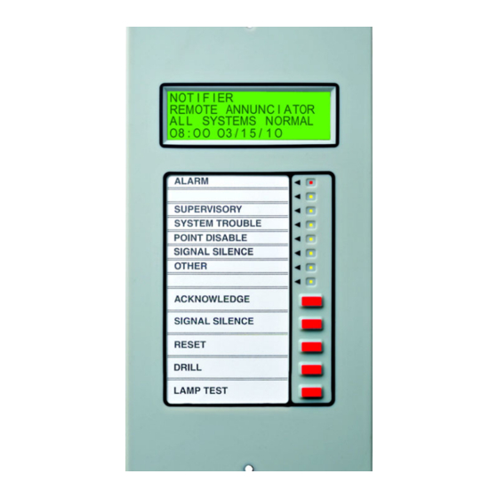
Section 4: Operating the LCD2-80 LED Locations (See “LED Indicators” on page 9 for functions). Alarm Future Use Buttons: Supervisory See “Buttons” on System Trouble page 18 below for Point Disable functions. Signal Silence *Acknowledge Other *Signal Silence Future Use *Reset Drill Display... -
Page 18: 3: Communications Failure Reporting
Operating the LCD2-80 Buttons Event priorities, in order of highest to lowest, are as follows: alarm, supervisory, security, non-fire with piezo, non-fire without piezo, trouble. A higher priority event that becomes active while a lower priority event is already active will cause the 20-character event mes- sage to change from displaying the lower-priority event to displaying the higher-priority event. -
Page 19: Appendix A: Eia-485 Shield Terminations
Appendix A: EIA-485 Shield Terminations The EIA-485 circuit must be wired using a twisted-shielded pair cable having a Characteristic Impedance of 120 ohms, +/- 20%. Do not run cable adjacent to, or in the same conduit as, 120-volt AC service, noisy electrical circuits that are powering mechanical bells or horns, audio circuits above 25 Vrms, motor control circuits, or SCR power circuits. - Page 20 Notes LCD2-80 Instruction Manual — P/N 53242:B5 07/26/2019...
- Page 21 Notes LCD2-80 Instruction Manual — P/N 53242:B5 07/26/2019...
- Page 22 EIA-485 Shield Terminations LCD2-80 Instruction Manual — P/N 53242:B5 07/26/2019...
- Page 23 Manufacturer Warranties and Limitation of Liability Manufacturer Warranties. Subject to the limitations set forth herein, Manufacturer warrants that the Products manufactured by it in its Northford, Connecticut facility and sold by it to its authorized Distributors shall be free, under normal use and service, from defects in material and workmanship for a period of thirty six months (36) months from the date of manufacture (effective Jan.
- Page 24 NOTIFIER 12 Clintonville Road Northford, CT 06472-1610 USA 203-484-7161 www.notifier.com...