Table of Contents
Advertisement
Quick Links
Advertisement
Table of Contents

Related Manuals for Honeywell SMX-AUS


Summary of Contents for Honeywell SMX-AUS
- Page 1 SMX-AUS Fire Alarm Control Panel (FACP) User’s Guide NS-MN-0032 / 11.2020...
- Page 2 In no event is Honeywell liable to anyone for any direct, special, or consequential damages. The information and specifications in this document are subject to change without notice.
- Page 3 User’s Guide SMX-AUS Fire Alarm & Emergency Communication System Limitations While a life safety system may lower insurance rates, it is not a substitute for life and property insurance! An automatic fire alarm system—typically made up of smoke detectors, heat detectors, manual call points, audible warning devices, and a fire alarm control panel (FACP) with remote notification capability—can provide early warning of a developing fire.
- Page 4 User’s Guide SMX-AUS Heat detectors do not sense particles of combustion and alarm only when heat on their sensors increases at a predetermined rate or reaches a predetermined level. Rate-of-rise heat detectors may be subject to reduced sensitivity over time. For this reason, the rate-of-rise feature of each detector should be tested at least once per year by a qualified fire protection specialist.
- Page 5 User’s Guide SMX-AUS Installation Precautions Adherence to the following will aid in problem-free installation with long-term reliability: WARNING - Several different sources of power can be connected to the fire alarm control panel. Disconnect all sources of power before servicing. The control unit and associated equipment may be damaged by removing and/or inserting cards, modules, or interconnecting cables while the unit is energized.
-
Page 6: Table Of Contents
User’s Guide SMX-AUS Table of Contents About this Guide ............................7 Main Menu .................................22 Supplemental Documentation ....................7 Manage ..................................22 Notice ................................7 View Devices ..............................22 Cautions and Warnings ........................8 7.1.1 LOOP DEVICES ......................23 7.1.2 PERIPHERALS ......................24 Standards .............................. -
Page 7: About This Guide
The images in the document are for reference purpose only and are subject to change. These instructions cover the programming and commissioning of the SMX-AUS Fire Alarm Control Panels (FACP). For any technical assistance email at HBTPacificFireSupport@Honeywell.com. -
Page 8: Cautions And Warnings
To ensure that you are installing and programming the latest features, we strongly recommend that you download the most current version of software for each product prior to commissioning any system. Contact Technical Support with any questions about software and the appropriate version for a specific application. The Technical Support email is: HBTPacificFireSupport@Honeywell.com. 1.6 Documentation Feedback Your feedback helps us keep our documentation up-to-date and accurate. -
Page 9: Introduction
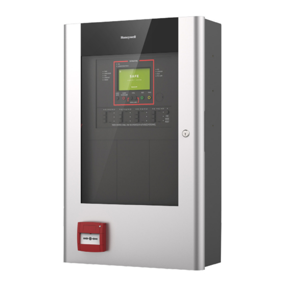
User’s Guide SMX-AUS Introduction The fire alarm control panel SMX-AUS is available with: • Metal enclosure with glass door and MCP • 1 loop and 2 loops (CLIP protocol) • 5-inch touch screen • LED indicators to know the status of power, system etc. -
Page 10: User Levels
User’s Guide SMX-AUS User Levels 3.1 Level Definition The FACP panel has four user Levels: Level 1, Level 2, Level 3, and Level 4. USER LEVEL 1 - The touch display is the primary indicator for the status of installation and provides detailed information about any current fire alarm, fault, supervisory, test and disablement condition. -
Page 11: Access Levels
User’s Guide SMX-AUS Access Levels The Access Levels for the FACP are: ACCESS LEVEL 1: The panel’s outer door is closed and locked. The visual and audible indications can be seen and heard through the transparent outer door. The manual call point on the outer door can be operated. -
Page 12: Front Panel Led Indications
User’s Guide SMX-AUS 5.2 Front Panel LED Indications The following table provides the details of the LED indications on the Panel: Indicator Color Function To Clear the Indication ALARM ROUTING ACTIVATED Red The Red LED flashes when the Alarm Relay on the Relay I/O Correct the condition causing the alarm and then perform Card is activated in fire condition. -
Page 13: Function Descriptions
User’s Guide SMX-AUS 5.3 Fire Fan Control Panel (FFCP) - User Control Keys - Function Descriptions Keys Descriptions Press to activate the Fire Fan in manual mode. AUTO Press to operate the Fire Fan in Auto mode. The Fire Fan operation shall be initiated by the alarm condition in the panel. -
Page 14: Status Display Indications
User’s Guide SMX-AUS 5.5 Status Display Indications The 800 x 480 multi-colour capacitive touchscreen is the primary status indicator. The panel can display and process various events, which are categorized broadly in the following categories: "Fire Events" "Supervisory Events" "Fault Events"... -
Page 15: User Interface Legend
User’s Guide SMX-AUS 5.5.2 User Interface Legend The sample legend details in this section identify the type of information shown across the screens. 5.5.2.1 Legend for Zones ZONE NUMBER ZONE LABEL DATE | TIME NUMBER OF DEVICES IN FIRE ZONE Fig. -
Page 16: Fire Events
User’s Guide SMX-AUS 5.5.3 Fire Events When there is a fire event, the panel screen automatically shows details about the fire condition. Information such as the total number of zones that are in fire, the first zone that detected the fire and the number of devices that are in the fire zone, are displayed on the screen. - Page 17 User’s Guide SMX-AUS 5.5.3.2 View Fire-Detected Devices The DEVICES IN FIRE tab contains the following details: • Device type • Device description • Zone number • Zone description • Loop number • Device address • Time-stamp The FIRE tab also shows status indications on the screen for the following outputs: •...
-
Page 18: Supervisory Events
User’s Guide SMX-AUS 5.5.4 Supervisory Events The SUP tab lists the supervisory events, which need to be attended. The supervisory events screen contains following details: • Device type • Device description • Zone number • Zone description • Loop number •... -
Page 19: Disabled Events
User’s Guide SMX-AUS 5.5.6 Disabled Events To access the disabled tab, tap DIS. The ALL tab contains the following details: • Disabled event description • Device type • Device description • Zone number • Zone description • Loop number •... - Page 20 User’s Guide SMX-AUS The ZONES tab contains the following details: • Zone number • Zone description • Number of Input devices disabled • Disabled or Partially disabled state Fig. 12: Disabled ZONES NS-MN-0032 / 11.2020...
-
Page 21: Test Events
User’s Guide SMX-AUS 5.5.7 Test Events To access the test events, tap TST. The ZONES tab displays the zones that are under test mode. The ZONES tab contains the following details: • Zone number • Number of input devices in the zone •... -
Page 22: Main Menu
User’s Guide SMX-AUS Main Menu The main menu is accessible by tapping the icon from the top left of all screens. The main menu provides programming menus as shown in the figure. Fig. 15: Main Menu Manage The Manage menu enables you to view the devices or to enable or disable the individual loop input devices, entire zones, logic zones and entire output groups. -
Page 23: Loop Devices
User’s Guide SMX-AUS 7.1.1 LOOP DEVICES The LOOP DEVICES tab shows details of loops and their devices. To access Loop Devices, perform the following steps: 1. In the VIEW DEVICES screen, tap the LOOP DEVICES option. 2. The Loop Devices screen appears. You can see the loops and the devices connected in each loop. -
Page 24: Peripherals
User’s Guide SMX-AUS 5. The following device details are displayed. This information is returned from the selected signalling loop device and is updated each time it is polled. DEVICE ADDRESS DEVICE TYPE LOOP NUMBER FIRE LEVEL PULSE WIDTH VALUE TIMING VALUE All the PW values are in µs. -
Page 25: Enable Or Disable
User’s Guide SMX-AUS 7.2 Enable or Disable You can enable or disable, individual loop input devices, entire zones, logic zones and entire output groups. 1. In the VIEW DEVICES screen, tap the ENABLE / DISABLE option. The following are the different options that are available under the enable or disable tab: •... -
Page 26: Enable Or Disable - Inputs
User’s Guide SMX-AUS 7.2.1 ENABLE OR DISABLE - INPUTS Perform the following steps to enable or disable a loop input device individually: 1. In ENABLE/DISABLE tab, tap INPUTS option. 2. The Inputs screen appears. You can see the loops and the input devices connected in each loop. -
Page 27: Enable Or Disable - Zones
User’s Guide SMX-AUS 7.2.2 ENABLE OR DISABLE - ZONES Perform the following steps to enable or disable zones: 1. In ENABLE/DISABLE tab, tap ZONES to enable or disable a zone. The Zones screen opens with a list of zones in the panel and the input devices associated to this zone. -
Page 28: Enable Or Disable - Logic Zone
User’s Guide SMX-AUS 7.2.3 ENABLE OR DISABLE – LOGIC ZONE Perform the following steps to enable or disable Logic Zones: 1. In ENABLE/DISABLE tab, tap LOGIC ZONES to enable or disable a logic zone. The Logic Zones screen opens with a list of programmed logic zones in the panel. - Page 29 User’s Guide SMX-AUS 4. The Details Screen appears as shown. You can see applicable operators, inputs and outputs of a logic zone. 5. Tap next to Loop Outputs to see details of each loop output device. Fig. 27: Logic Zone Details 6.
-
Page 30: Enable Or Disable - Output Groups
User’s Guide SMX-AUS 7.2.4 ENABLE OR DISABLE - OUTPUT GROUPS You can enable or disable an output group in the panel. 1. Tap OUTPUT GROUPS. 2. All output groups in the panel are listed. 3. Tap ENABLE to enable the output group or tap DISABLE to disable the output group. -
Page 31: Maintenance
User’s Guide SMX-AUS Maintenance To perform the Maintenance steps, tap and select the Maintenance tab. The Maintenance screen has the following tabs: 1. RUN TEST. 2. ALARM COUNT and VOLTAGES. 3. PANEL INFO. 8.1 RUN TEST The RUN TEST tab has the following options: •... - Page 32 User’s Guide SMX-AUS 3. In the From zone number enter the zone number beginning the range, and in the To zone number, enter the zone number ending the range. 4. Tap SELECT SOUNDERS to select the mode of test. Fig. 32: Zone Range 5.
- Page 33 User’s Guide SMX-AUS 7. The following screen opens. Choose either Onboard or Loop circuits. Fig. 34: Zone Test – Test with selective sounder 8. For Onboard circuit, the following screen opens. Select either Sounder 1 or Sounder 2 and tap ASSIGN. You can tap UNASSIGN to clear the selection.
- Page 34 User’s Guide SMX-AUS 10. For Loop circuit, the following screen appears with the list of zones in the panel and the sounder output devices associated with each zone. Tap next to the selected zone. Fig. 36: Zone Test – Test with Loop sounder – Select Zone 11.
-
Page 35: Other Tests
User’s Guide SMX-AUS In the Zone Test screen, you can see the number of zones that are in test, along with the selected sounder. To stop testing all the zones, tap STOP ALL. Fig. 38: Zone Test – Stop All 8.1.2 Other Tests... - Page 36 User’s Guide SMX-AUS 8.1.2.1 LED Test The panel will test all the system status LED indicators one after another, and then repeat the test again and again. It can only be stopped manually. Perform the following steps to run the LED Test: 1.
-
Page 37: Alarm Count & Voltages
User’s Guide SMX-AUS 8.1.2.3 LCD Screen Test Perform the following steps to run the LCD Screen Test: 1. In the RUN TEST screen, tap LCD TEST. 2. A screen opens to show the five different colours like red, green, blue, white and black. -
Page 38: Panel Info
User’s Guide SMX-AUS 8.3 Panel Info The PANEL INFO tab provides the following information: Options Description SERVICE INFO Next service due The date of the next scheduled service visit Service company name Name of the service organization Phone number Phone number of the service organization... -
Page 39: Event Log
User’s Guide SMX-AUS Event Log From any screen, tap and select the Event Log tab to see the list of events that occurred in the panel. Fig. 43: Event Log NS-MN-0032 / 11.2020... -
Page 40: Quick Settings
User’s Guide SMX-AUS 10 Quick Settings From any screen, tap and select the Quick Settings tab to set the date and time by using the number keys and Programmable zones delay -ON/OFF. The time is set in 24 hours format. - Page 41 User’s Guide SMX-AUS Notes NS-MN-0032 / 11.2020...
- Page 42 User’s Guide SMX-AUS Notes NS-MN-0032 / 11.2020...
- Page 43 User’s Guide SMX-AUS Notes NS-MN-0032 / 11.2020...
- Page 44 HONEYWELL BUILDING TECHNOLOGIES 9 Columbia Way Baulkham Hills, NSW 2153 Tel: Australia - 1300 368 755 HBTPacificFireSupport@honeywell.com E-Mail: Technical changes reserved! www.honeywell.com © 2020 Honeywell International Inc. Website:...