
Related Manuals for Rinnai EX38DT


Summary of Contents for Rinnai EX38DT
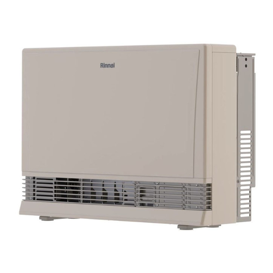
- Page 1 MODEL: EX38DT (RHFE-1006FTA) Direct Vent Wall Furnace Installation and Operation Manual RHF1006-1750(02)
- Page 2 fied kit is used. Copyright 2022 Rinnai America Corporation. Rinnai® is a registered trademark of Rinnai Corporation used under license by Rinnai America Corporation. Rinnai America Corporation continually updates materials, and as such, content is subject to change without notice.
-
Page 3: Table Of Contents
6. Maintenance ..........................38 7. Troubleshooting ........................39 8. Parts ............................41 9. Appendices ..........................51 9.1 Massachusetts State Gas Regulations ................51 9.2 Wiring Diagram ....................... 52 9.3 Ladder Diagram ......................53 10. Warranty ..........................54 EX38DT Installation and Operation Manual... -
Page 4: Welcome
1. Welcome Thank you for purchasing a Rinnai Direct 1.2 To The Consumer Vent Furnace. Before installing and operating the direct vent furnace, be sure to read these instructions completely and carefully to You must read the entire manual to properly familiarize yourself with the direct vent operate the direct vent furnace. -
Page 5: Safety
Do not operate furnace with the panels or moderate injury. It may also be used to removed, cracked or broken. alert against unsafe practices. Replacement of the panels should be performed by a trained and qualified professional. EX38DT Installation and Operation Manual... - Page 6 9. After it has been determined that each appliance connected to the venting system properly vents when tested as outlined above, return doors, windows, exhaust fans, fireplace dampers and any other gas-fired burning appliance to their previous conditions of use. EX38DT Installation and Operation Manual...
-
Page 7: About The Direct Vent Furnace
Flue Manifold (Combustion/Exhaust) ⓬ Rating plate (includes model number, ❺ serial number, gas type, etc.). English Bent Elbow ⓭ is on the right side; French is on the left side. ⓮ Exhaust Pipe Pipe Stopper ⓯ EX38DT Installation and Operation Manual... -
Page 8: Specifications
The efficiency rating of this furnace is a product thermal efficiency rating determined under continuous operating conditions and was determined independently of any installed system. Rinnai products are continually being updated and improved; therefore, specifications are subject to change without prior notice. -
Page 9: Dimensions
Front View (Including Sample Wall Template Located on Furnace Carton Box) Center of Furnace Wall Bracket Wall Opening Position The hole center should be within the shaded area. Wall Opening Position Figure 3: Front View Side View Figure 4: Side View EX38DT Installation and Operation Manual... -
Page 10: Installation
Standard, Title 24 CFR, Part 3280, or, when such a installation of direct vent furnaces. Training for standard is not applicable, the standard for Rinnai Direct Vent Furnaces is accessible online at Manufactured Home Installations, ANSI Z225.1, or rinnaipro.myabsorb.com. the standard for Gas Equipped Recreational Vehicles and Mobile Housing, CSA Z240.4. -
Page 11: What You Will Need
4.2 What You Will Need 4.2. 1 Items Included Unpack the Rinnai Direct Vent Furnace package and verify the following contents are included. If any items are damaged or missing, contact your local dealer/distributor or call Rinnai Customer Care at 1-800-621-9419. -
Page 12: Choose An Installation Location
Chemicals that are corrosive in nature should not be stored or used near the furnace or vent termination. Damage and repair due to corrosive compounds in the air is not covered by warranty. EX38DT Installation and Operation Manual... - Page 13 [2] Permitted only if veranda, porch, deck, or balcony is fully open on Clearance to opposite wall is 24 inches (60 cm). a minimum of two sides beneath the floor. EX38DT Installation and Operation Manual...
- Page 14 40 in. (1 m) from the front, and the area shown above the furnace in the figure to the left. Rinnai recommends 10 in. (254 mm) clearance from the top and on both sides for servicing. Figure 7: Service Clearances...
- Page 15 Manufactured Home Construction and Safety Standard, Title 24 CFR, Part 3280 and/or CAN/SCA Z240 MH Series, Mobile Homes. Leave the entire manual taped to the furnace or give the manual directly to the consumer. EX38DT Installation and Operation Manual...
-
Page 16: Installation Steps
Figure 8 Figure 9 4.4.2 Attach Wall Brackets Attach the wall brackets as shown. A template is provided. 28 7/16 in. (723 mm) 1 3/16 in. (30 mm) 15/16 in. (24 mm) Wall Bracket Figure 10 EX38DT Installation and Operation Manual... - Page 17 This furnace can only be used with one be removed. Cut the outer plastic laminate of the five types of Rinnai flue kits. The (with a utility knife or similar) and remove the flue kits and their dimensions are listed extension.
- Page 18 (Ʌ) Top Terminal seal Apply silicone sealing evenly Terminal around the entire seal. Locking tie Put silicone sealing evenly around the perimeter without any gaps between the terminal seal and rough wall surface. Figure 15 EX38DT Installation and Operation Manual...
- Page 19 Push the assembly into the terminal tube, ensuring that the seal is in place on the inner tube. Attach the inside connection with 3 screws. The inner connection can still be turned to install the screws. 3 screws Figure 17 EX38DT Installation and Operation Manual...
- Page 20 Pipe Stopper A 1001F-250 Pipe Stopper B FOT 111-6 Top Stopper FOT 062-7 Pipe Clamp FOT 064-11 2 Sets 3 Sets 4 Sets Wall Fixture FOT 064-12 FOT 062-10 Screw A ZAA0420SC Screw B CP-30408 EX38DT Installation and Operation Manual...
- Page 21 5. Clearances: Exhaust pipe to combustibles: 1 in. (25.4 mm) Exhaust pipe to non-combustibles: 0 in. (0 mm) NOTE The EX38DT is capable of two vent length 2/3 in. settings: 3° Short Vent: 0 - 7 ft + 1 elbow 1 Ft ...
- Page 22 Do not allow any low points in the exhaust line. Figure 21 Figure 22 NOT CORRECT CORRECT Slope horizontal sections 3° downward 90° Elbow Up 3° Configuration Exhaust Exhaust Intake Intake Figure 23 EX38DT Installation and Operation Manual...
- Page 23 Bend to desired angle. Do not cut the intake hose. Cutting the intake hose may result in noise. Do not straighten the bent pipe attached to the furnace. EX38DT Installation and Operation Manual...
- Page 24 Figure 28 4. Slide the insulation sleeve up to the flue manifold and slip the securing clip over the sleeve as shown. Up to 3/8 in. (10 mm) Insulation Adjustable Leg Sleeve Figure 29 Figure 32 EX38DT Installation and Operation Manual...
- Page 25 Supplied The regulator has been factory pre-set. If gas pressure must be within the limits the pressure is incorrect, contact Rinnai shown in section “3.2 Specifications.” technical support. Refer to an approved pipe sizing chart if in doubt about the size of the gas line.
- Page 26 3.8 in. 3.0 in. 2.7 in. 2.5 in. 6.4 in. 5.6 in. 5.1 in. 4.6 in. pressure - W.C. (96 mm) (76 mm) (68 mm) (62 mm) (162 mm) (143 mm) (129 mm) (116 mm) High EX38DT Installation and Operation Manual...
- Page 27 A. Check for Gas Leaks at the Test Points. Yellow or orange flames Figure 34: Normal and Abnormal Flames 16. Install the front panel. 17. If doing a gas type conversion, place the new conversion rating plate (label) on the front cover. EX38DT Installation and Operation Manual...
-
Page 28: Post-Installation Checklist
If you answer NO to any question, installation is not complete. Refer to the applicable section in this manual for additional information. For assistance, contact your local dealer or distributor, or call Rinnai Customer Care at 1-800-621-9419. INSTALLATION LOCATION Have you verified the unit and vent termination meet the clearance requirements? ... -
Page 29: Operation
Do not sit on the furnace. — Installa on and service must be Do not place containers of liquid on top of performed by a licensed the furnace. Water spillage can cause professional. extensive damage to the furnace and may result in electric shock. EX38DT Installation and Operation Manual... -
Page 30: Operating Instructions
Keep burner and control located on control panel.) compartment clean. See installation and operating 3. Locate the manual gas valve. instructions. 4. Turn the manual valve clockwise to the full OFF position. EX38DT Installation and Operation Manual... -
Page 31: Control Panel
To turn the furnace off, press the ON/OFF button. The ON indicator light will go out. The fan will continue to operate for several minutes after the burner has gone out in order to cool the furnace. Do not unplug the furnace while the fan is running. Figure 36 EX38DT Installation and Operation Manual... - Page 32 2. The light next to “Clock” should be flashing. H - burner is on maximum combustion Press the up and down arrows to set the time. Holding down either of the arrow keys will change the time more quickly. Figure 39 EX38DT Installation and Operation Manual...
- Page 33 DISPLAY in either mode. Error codes will not show on the remote thermostat even when in remote thermostat mode.) IMPORTANT The remote thermostat will NOT control the furnace’s ability to power on or power down. This must still be done by using the ON/OFF button of the furnace. EX38DT Installation and Operation Manual...
- Page 34 “Override” button Timer 1 Temp Position is flashing. Press the will return the furnace to the up or down arrows to set the temperature. operation of the current timer period. Flashing Figure 48 Figure 46 EX38DT Installation and Operation Manual...
- Page 35 The Set Back feature is intended to prevent the installation location from falling below a specified temperature. It is not intended as an Figure 50: Economy Mode alternate thermostat, but rather a preventative measure against freezing. EX38DT Installation and Operation Manual...
-
Page 36: Add Water To The Humidifier
Use a screw driver or similar object to bend furnace will attempt to restart after 1 hour. If the each louver to the desired position. flame is extinguished after this period then the furnace will immediately attempt ignition. EX38DT Installation and Operation Manual... -
Page 37: Diagnostic Codes
You may be able to clear the fault code by turning the furnace off and then on again. If the fault code remains or returns on the next operation, contact Rinnai or your nearest service agent and arrange for a service call. -
Page 38: Maintenance
Refer to “Flue Terminal Clearances” in section “4.3.2 Clearances.” The Yellow or clearance in Ref. A should be maintained orange flames from any snow accumulation. Figure 57 EX38DT Installation and Operation Manual... -
Page 39: Troubleshooting
High efficiency appliances tend to discharge water vapor terminal. on cold days. This is normal. Unit cuts off without apparent Check whether filters are blocked. Dirty filters will cause reason. the heater to overheat. EX38DT Installation and Operation Manual... - Page 40 Air Filter Clean Filter Blocked Gas Escape Service Call Lock Set Cancel Lock Gas Off at Meter, Tank, or Turn Gas On Valve Cancel “ON” ON Timer is set Timer EX38DT Installation and Operation Manual...
-
Page 41: Parts
8. Parts Cut-Away Diagram Figure 58 EX38DT Installation and Operation Manual... - Page 42 Exploded View of Service Parts Figure 59 EX38DT Installation and Operation Manual...
- Page 43 Exploded View of Service Parts Figure 60 EX38DT Installation and Operation Manual...
- Page 44 Exploded View of Service Parts Figure 61 EX38DT Installation and Operation Manual...
- Page 45 Exploded View of Service Parts Figure 62 EX38DT Installation and Operation Manual...
- Page 46 Exploded View of Service Parts Figure 63 EX38DT Installation and Operation Manual...
- Page 47 STRAIGHTENING PLATE A 209000163 PCB UNIT MOUNTING ACCESSORY PLATE 209000165 HUMIDIFIER TRAY HOLD PLATE LEFT 208000057 HUMIDIFIER TRAY HOLD PLATE RIGHT 208000058 TOP PLATE SUPPORTER 209000168 TOP PLATE HOLDER 209000169 BURNER BOX SEAL PLATE 206000039 EX38DT Installation and Operation Manual...
- Page 48 206000051 INTER CONNECTION 209000172 O RING M10B‐1‐10 CONNECTING TUBE RETAINER 209000079 PACKING C3I1‐7 GAS FILTER 206000052 GAS INLET 431F‐1110 ELECTRODE PACKING B 205000075 TEST PORT SCREW AU39‐965 AIR INLET D 208000059 AIR INLET PACKING 1004F‐2033 EX38DT Installation and Operation Manual...
- Page 49 OPERATION PC BOARD ASSY 205000098 POWER SUPPLY CORD 205000082 PRESSURE SENSOR 208000069 PRESSURE SENSOR HARNESS 205000099 POWER SUPPLY CORD 205000100 SENSOR HARNESS 205000101 IG HARNESS 205000102 TF HARNESS 205000103 HILIMIT THERMISTOR 205000104 ROOM THERMISTOR 205000105 EX38DT Installation and Operation Manual...
- Page 50 WATER LEVEL LINE LABEL B 209000213 OPERATION MANUAL 200000088 OPERATION LABEL 209000214 FRONT PANEL EMBLEM 209000215 FRONT PANEL EMBLEM 209000216 Conversion Kits (Optional) Model For Converting to Natural Gas For Converting to Propane EX38DT (RHFE-1006FTA) 203000011 203000012 EX38DT Installation and Operation Manual...
-
Page 51: Appendices
This direct-vent appliance must be installed by a installed. state qualified or licensed contractor and a 2. APPROVED CARBON MONOXIDE properly trained Rinnai Installer. If you are not DETECTORS. Each carbon monoxide properly trained, you must not install this unit. detector as required in accordance with the... -
Page 52: Wiring Diagram
Fuse Sparker Electrode SV1,2 Main Solenoid Valve 1,2 green Solenoid Valve 3 Modulating Solenoid Valve white Pressure Sensor Combustion Fan Motor yellow FR1,2 Flame Rod 1, 2 gray orange Figure 64: Wiring Diagram EX38DT Installation and Operation Manual... -
Page 53: Ladder Diagram
Main CPU Central Processing Unit Modulating Solenoid Valve Sub CPU Central Processing Unit for Safety FR1,2 Flame Rod 1, 2 B1~4 Burner 1~4 Convection Fan Pressure Sensor Convection Fan Motor W.TH Wall Thermostat Figure 65: Ladder Diagram EX38DT Installation and Operation Manual... -
Page 54: Warranty
Rinnai’s sole discretion. The warranty claim for product parts and labor may be denied if a component or product returned to Rinnai is found to be free of defects in material or workmanship; damaged by improper installation, use or operation; or damaged during return shipping. - Page 55 Limitation on Warranties No one is authorized to make any other warranties on behalf of Rinnai America Corporation. Except as expressly provided herein, there are no other warranties, expressed or implied, including, but not limited to warranties of merchantability or fitness for a particular purpose, which extend beyond the description of the warranty herein.
- Page 56 Rinnai America Corporation 200000082(01) 103 International Drive 1/2022 Peachtree City, GA 30269 RHF1006-1750(02) Tel: 1-800-621-9419 Web: rinnai.us rinnai.ca...