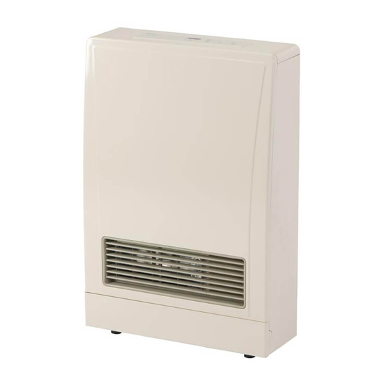
Rinnai ENERGYSAVER EX08C Installation Fundamentals
Direct vent wall furnace
Hide thumbs
Also See for ENERGYSAVER EX08C:
- Conversion manual (12 pages) ,
- Brochure & specs (5 pages) ,
- Operation and installation manual (80 pages)
Table of Contents
Advertisement
Advertisement
Table of Contents

Related Manuals for Rinnai ENERGYSAVER EX08C


Summary of Contents for Rinnai ENERGYSAVER EX08C
- Page 1 Rinnai ENERGYSAVER® Direct Vent Wall Furnace Installation Fundamentals...
-
Page 2: Installation Fundamentals
Rinnai ENERGYSAVER Direct Vent Wall Furnace ® Installation Fundamentals The following course is approved for NATE continuing education hours (CEH’s). This course will earn the following CEH’s: Warm Air Heating-Gas-Installer – 2 hours Warm Air Heating-Gas-Service – 2 hours If you require credit for NATE, please notify the... - Page 3 Rinnai Service and Support (800-621-9419) Rinnai America’s phone support structure consists of the following departments: • CRC – Consumer Response Center – Fielding general calls, consumer questions, etc. • Available in office from 8 a.m. to 8 p.m. EST, Monday - Friday •...
- Page 4 Product Model Numbers and Specifications INPUT BTU AFUE PREVIOUS MODELS CFM* DECIBELS* MODELS POWER* RANGE* (Efficiency)* NG-82% EX08C ES08, RHFE 201 FA 55.5-82.0 41-42 W 27-36dB 3,000-8,000 NG/LP LP 83% 5,500-11,000 NG NG-81% EX11C ES11, RHFE 263 FAII 69.3-102.5 44-47 W 31-38dB LP-82% 5,700-11,000 LP...
- Page 5 Features and Benefits • When sized correctly, the ENERGYSAVER® Furnace can be used as a whole house/primary heat source. • Easy Control and Operation • One-touch ignition • Programmable thermostat with a temperature range between 55°F to 95°F (13°C to 35°C) •...
- Page 6 Features and Benefits • The unit’s standby power consumption is less than 1 watt. • Seven-stage Intelligent Modulating Gas Valve and blower control. • Warm air discharge at floor level. o Directional louvers to optimize direction of air flow. • Ultra-quiet operation-Decibel range of 27-47 is comparable to a normal conversation.
- Page 7 Safety Features • Self Diagnostic Circuitry-Should the ENERGYSAVER® detect an unsafe operating condition, the unit will shut down and a fault code will display indicating the specific issue. o If the code is due to an ignition or combustion failure, the unit will attempt to relight automatically.
- Page 8 Safety Features • Overheat protection- Multiple temperature sensors monitor the appliance’s temperature. Shut down occurs if an unsafe operational temperature is detected. • Combustion and convection fan validation-should either of these fans fail to maintain the proper speed (likely due to a restriction), the PCB will not allow the unit to operate.
-
Page 9: Energy Saver
• Visit http://www.acca.org/ for more information. • Rinnai also offers a basic DV sizing calculator at http://www.rinnai.us/heat_selector_2007.swf • NOTE: Incorrectly sized applications can lead to the ENERGYSAVER short- cycling or failing to bring the area to the desired set point temperature. -
Page 10: Key Concepts
—Whole House Furnaces ENERGYSAVER ® Key concepts The ENERGYSAVER has the ability to heat an entire structure from a central room. Here’s how: • 2 law of thermodynamics – Heat seeks cold • Once the main room approaches the set point temperature, the heat begins to move to other rooms—seeking cold. - Page 11 —Whole House Furnaces ENERGYSAVER ® Key concepts • Variable speed technology – Modulating gas and air based on the heat loss at that moment • With on/off single stage operation, gas usage • The Energysaver’s modulating technology has the can be high due to alternating periods between ability to replace only the heat escaping the maximum flame and no flame at all structure by continuously operating at heating levels...
-
Page 12: Direct Vent Furnaces
ENERGYSAVER Direct Vent Furnaces ® Operation Sequence 1. Combustion fan purges heat chamber, PCB Concentric Termination verifies fan rotation Convection Fan 2. Ignition spark begins 3. When sensing electrode detects spark, gas valve assembly opens 4. Ignition occurs and heat exchanger warms 5. - Page 13 Control Panel Review (C-Series models) EX08C, 11C, 17C, Operation Lamp Temperature Control and Display- Restricted Green = standby Display will enter a power saving dimmer mode Filter 22C MODELS Solid red = when flame is present during normal operation Indicator Flashing red = fault code is present Child Safety...
- Page 14 Control Panel Review (C-Series models) Description Key The following pages will cover each topic in detail Child Safety Lock Economy Feature Timer 1 and 2 EX08C, 11C, 17C, 22C MODELS Note: While off, pressing Timer 1 and 2 together will change the display from Fahrenheit to Celsius Override Temporarily bypasses timers...
- Page 15 Control Panel Review (all other current models) ES38 MODELS Production before 7/2011 Temperature Control and Display Room temp lamp stays on Room temp displays only when adjusted Economy Feature Function Lock - Pressing both arrows will engage The below table shows the temperature range of all models Fahrenheit L (approx.
- Page 16 Economy Function Economy Mode is designed to save gas usage over time. • The Economy Function is based on the theory that the human body cannot detect small temperature changes over an extended period of time. • 30 minutes after the set point temperature is achieved, the unit will reduce the temperature by 2°F.
- Page 17 Clock, Timer, and Setback Functions (C-Series) C-Series ENERGYSAVERS® have two primary methods of operation: • Exclusively as a thermostatically controlled furnace • When left to operate on a continuous-run basis using feedback from its thermostat, the ENERGYSAVER will achieve an optimum balance between comfort and efficiency.
- Page 18 Clock, Timer, and Setback Functions (C-Series) • If needed, the Override button can be selected to temporarily turn on or off the timers to allow manual operation. • If the unit is operating during a Timer’s event, pressing Override will turn the unit off until the next Timer’s event.
- Page 19 Clock, Timer, and Setback Functions (C-Series) Setback allows a minimum temperature to be pre-set and maintained between timer events or while the unit is turned off. • This feature’s primary function is to slightly reduce the temperature (and gas usage) during extended periods of nonuse or inactivity—such as sleeping or when the home is empty.
- Page 20 Restart Features All ES, EX, and C-Series models will attempt restart after a power failure or flame failure to ensure heating is not interrupted for extended periods of time. • If there is a power failure while the appliance is operating, the unit will attempt to restart automatically when the power is restored.
- Page 21 Restart Features • Should a high gust of wind, gas outage, etc. occur that affects the flame characteristic, the unit will automatically shut down, purge the combustion chamber, and re-ignite. • If the unit cannot ignite or maintain flame for 15 seconds after ignition, code 11 will flash and the unit will try to ignite again in one hour.
-
Page 22: Fault Codes
Fault Codes • A fault code will flash on the unit when a fault occurs. The unit will stop operating. • Operation intervention is required for all codes EXCEPT a code 11. • To view the last nine fault codes, with the unit OFF, press the UP, DOWN, and, ECONOMY buttons simultaneously CODE PROBABLE CAUSE COMMENTS... -
Page 23: Warranty And Maintenance
Warranty and Maintenance • Warranty Rinnai ENERGYSAVER Furnace Warranty ® Heat Exchanger Coverage Parts Reasonable Labor 10 years 5 years 2 years Refer to each model’s installation and owner manual for full warranty details • Maintenance and Service • The appliance should be inspected at least annually by a qualified service technician—see the installation... - Page 24 ® converted from NG to LP or LP to NG. • Depending on model and year of manufacture, a conversion kit may be included with the product. If not, contact Rinnai for information on acquiring the proper kit (1-800-621-9419).
- Page 25 Maximum Temperature Limit • All ENERGYSAVER models now have the ability to set a maximum temperature limit directly ® from the control panel. This procedure is NOT in the manuals to allow property owners and managers to control this setting as needed. •...
-
Page 26: Installation Overview
Installation Overview This overview is not meant as a substitute for the installation and owner’s manual. Every furnace is shipped with a manual that should be followed completely. The following is a supplemental presentation and is intended as a tool for the first time installer. QUALIFIED INSTALLING AGENCY The installation must conform to local codes, in the absence of local codes, the installation must conform with American National Standard (National Fuel Gas Code) known as NFPA 54... - Page 27 Installation Guidelines The following guidelines are from the installation / owner’s manual. Before beginning the installation process, please review the following: •A manufactured home (USA only) or mobile home OEM installation must conform with the Manufactured Home Construction and Safety Standard, Title 24 CFR, Part 3280, or, when such a standard is not applicable, the standard for Manufactured Home Installations, ANSI/NCSBCS A225.1, or the standard for Gas Equipped Recreational Vehicles and Mobile Housing.
- Page 28 Installation Guidelines The following guidelines are from the installation / owner’s manual. Before beginning the installation process, please review the following: • This appliance discharges a large volume of warm air next to the floor. Any particles in the air such as cigarette smoke could cause discoloration in carpet. The warm air flow could discolor nylon carpets containing dyes or vinyl surfaces.
- Page 29 Recommended Tools Needed for Installation • Cordless / Electric drill • 3 inch hole saw • 5/8 inch X 18 inch pilot drill bit • 1/8 inch drill bit (not shown) • No. 2 Phillips bit • No. 2 Phillips screwdriver •...
- Page 30 View of Properly Installed Unit...
- Page 31 Furnace Packaging and All Hardware *Included with furnace: Ensure correct gas type is on package! • Installation and owner’s manual • Wall termination that will fit wall thickness of 4.5”-9.5” • Wall mounting back spacers • Mounting screws • Vent locking clamps •...
- Page 32 Furnace Packaging and Hardware Inspect packaging to ensure all parts and Top of box contains screw installation materials are removed before hardware, back-spacers, vent discarding. termination, etc. Documentation packet contains: installation manual and Warranty registration Installer: Leave all documentation with unit Consumer: Retain all documentation for future use WARNING...
- Page 33 Furnace Packaging and all Hardware HARDWARE PACKET Machine screws for attaching exhaust pipe to termination sleeve Back spacer mounting Screws for attaching exhaust brackets sleeve (3) and top back spacer (2) to wall Exhaust pipe stoppers and Sheet metal screws for clamps attaching back spacers to furnace...
- Page 34 Installing On Combustible Flooring • When the furnace is installed directly on carpeting or other combustible material (excluding wood flooring), it must be installed on a metal or wood panel extending the full width and depth of the heater. • The furnace may be installed on combustible wood flooring. 3.
-
Page 35: Furnace Location
Identifying the Installation Location FURNACE Zero clearance to back wall and above LOCATION Maintain 9” (225 mm) 2” Furnace must be above for filter removal 2” (50 mm) (50 mm) installed where the proper clearances from combustibles can be maintained. Also ensure installation location Maintain 10”... -
Page 36: Vent Location
Identifying the Installation Location VENT LOCATION Consider the following requirements when locating the outside vent termination: • 12” clearance from grade or anticipated snow level (ANSI Z223.1) • 9” clearance from a door or window that may be opened (ANSI Z223.1) •... - Page 37 Interior Wall Preparation TEMPLATE PLACEMENT Included with each furnace is a wall template to simplify mounting and vent hole location—2010 and newer models have the template printed on the cardboard packaging. 1. Cut the template out of the box. 2. Ensure bottom of template is cut correctly.
- Page 38 Interior Wall Preparation Score two mounting CAUTION SCORING THE WALL screw holes (⅛” bit) Practice good safety habits when using power equipment 1. Ensure vent hole will NOT compromise any structure support (stud), electrical, plumbing, HVAC system, etc. 2. Score the template anywhere in the shaded arc for the pilot bit.
-
Page 39: Installing The Mounting Bracket
Interior Wall Preparation INSTALLING THE MOUNTING BRACKET Using the two previous scored screw holes, mount the rear mounting bracket to the wall. - Page 40 Interior Wall Preparation DRILLING THE VENT HOLE 1. Interior: Using a 3” inch hole saw, drill the vent hole guided by the previously drilled pilot hole. NOTE: Drill holes level or sloped downward 2°to the outside. Vent termination must have outward pitch to ensure condensation drains to the outside.
- Page 41 Initial Gas Line Preparation ATTACHING THE GAS CONNECTION (Part 1) 3. If using appliance flex 1. Prepare the drip leg for furnace gas line (recommended), connection. NOTE: Do not attach flair adaptor to the attach the right side back drip leg. NOTE: The spacer yet to allow enough 2.
- Page 42 Furnace Preparation INSTALLING THE LEFT AND RIGHT BACK SPACERS The left and right back spacers are installed with a tab and slot at the Ensure two locking top and middle and single screws tabs align correctly at the bottom of the panels. ROOM AIR THERMISTOR NOTE: The room air thermistor comes with approximately 14”...
- Page 43 Furnace Preparation INSTALLING THE AIR INTAKE HOSE CLIP Mount the hose clip at the bottom of the furnace as shown below. Models prior to 2010 use a clip in this Use the longer tie-wrap location-see manual for details. included with hardware...
-
Page 44: Vent Termination
• Clearance to combustibles for the vent sleeve and flanges is zero inches. • This appliance can only be used with one of the five types of Rinnai vent kits. These kits and their dimensions are listed below and in each owner’s/installation manual. - Page 45 Vent Termination FLUE MANIFOLD DISASSEMBLY • The flue manifold consists of 3 parts: • Inside connection • Sleeve • Outside terminal 2. To remove the outer terminal 1. Disassemble the flue manifold by first NOTE: Make sure the pull and release the two pulling out the inside connection.
- Page 46 Vent Termination ADJUSTING THE SLEEVE LENGTH Do not extend vent beyond the red line! 1. Measure the wall thickness through the previously drilled hole. The end of the sleeve should protrude 3/16” – 3/8” (5- 2. If a shorter length is 10mm) from the outside wall.
- Page 47 Vent Termination ATTACHING THE SLEEVE 1. Slide the sleeve through 2. Ensure the 3. Attach the sleeve to the the interior side of hole. sleeve extends inside wall using 3 Ensure label “Top” is 3/16” to 3/8” (5- screws. If needed, use installed at the top of hole.
- Page 48 Vent Termination INSTALLING THE OUTER VENT TERMINAL 1. From the 3. On the inside, outside, insert pull hard on the the terminal into left and right Lock in notches the sleeve with hand ties. Clip the marking the ties over the “TOP”...
- Page 49 Vent Termination INSTALLING THE INSIDE CONNECTION ASSEMBLY 1. Push the 2. Attach the inside assemble into connection with 3 the terminal screws. tube with the label “top” matching the location on the sleeve. Ensure that the seal is in place on the inner tube.
- Page 50 Vent Termination OUTSIDE VIEW OF CORRECTLY INSTALLED TERMINATION...
- Page 51 Final Gas Line Preparation ATTACHING THE GAS CONNECTION (Part 2) Tip: Using a flexible appliance gas line will enable the furnace to be slid into place with minimal effort. 2. Attach the included shut off 1. Ensure all connections 3. NOTE: Many models will valve and field supplied are properly tightened allow the gas valve to be...
- Page 52 Sliding the Furnace into Place SLIDING THE FURNACE INTO PLACE 2. Slide the furnace into place. Ensure furnace is level and aligned to vent 1. If necessary, the unit can be termination, back spacer mounting leveled using the adjustable legs bracket, and gas line (if necessary).
- Page 53 Connecting the Vent Flue CONNECTING THE VENT FLUE The following components can be connected by reaching behind the appliance as it is positioned against the wall NOTE: NEVER bend the exhaust pipe that exits the furnace! 1. Slide the stainless steel exhaust tube 2.
- Page 54 Connecting the Vent Flue CONNECTING THE VENT FLUE (continued) The following components can be connected by reaching behind the appliance as it is positioned against the wall Insulation sleeve 3. Fit the locking clamp over the connection between the 4. Slide the insulation sleeve up to sliding tube and manifold.
- Page 55 Connecting the Air Intake CONNECTING THE AIR INTAKE The following components can be connected by reaching behind the appliance as it is positioned against the wall: 1. Connect the air intake hose to Using the zip tie provided, the side of the termination. fasten the air intake to the NOTE: NEVER cut the gray termination.
- Page 56 Installing the Top Back Spacer The following components can be connected by reaching behind the appliance as it is positioned against the wall. 1. Install the bracket on the rear of 2. Place top back spacer on the back of furnace, clipping the top spacer with 2 decorative the spacer bracket into the wall bracket.
- Page 57 Installing the Top Back Spacer (continued) 1. Insert screws for top spacer on right and left side of back spacers. 2. Tighten two sheet metals screws on top back spacer.
-
Page 58: Prepare For Operation
Prepare for Operation 1. If needed remove the toe kick plate to fill the humidifier tray. 2. Fill the humidifier tray according to the installation manual. Replace toe kick plate. 1. To direct air flow, if needed, the front louvers can be adjusted after removing louver plate (5 screws). - Page 59 ES38 Vent and Gas Connection Differences Shipped with each ES38 is a vent adaptor that Included with the ES38 is male to female “street” elbow to reduces the 50 mm diameter exhaust to 30 mm for connection to vent termination. attach to the unit before a NOTE: If using extension sets, this reducer union or flex line.
- Page 60 Extended Venting And High Altitude Installation Procedures...
- Page 61 Vent Extension Installation Requirements The following is an overview of guidelines and installation of Rinnai Direct Vent Furnace vent extensions. This is not a substitute for any current installation / owner’s manual or vent instructions. • The 08 series can not use vent extensions.
- Page 62 Vent Extension Installation Requirements The following is an overview of guidelines and installation of Rinnai Direct Vent Furnace vent extensions. This is not a substitute for any current installation / owner’s manual or vent instructions • The exhaust elbow assembly attached on the back of the unit must remain as a 90° elbow. Never bend or straighten this component.
- Page 63 Specific Venting Changes • The table below illustrates each model’s permissible vent length and kit part numbers ES17/EX17(C) MODEL ES08/EX08C ES11/EX11C ES38 ES22/EX22(C) Total extended vent limit 13 feet 13 feet 13 feet Extended 8 feet (unless greater Vent than 2000’ altitude then Total vertical limit 10 feet 13 feet...
- Page 64 PCB Adjustments for extended venting or high altitude MODELS: EX08C, EX17C, EX22C, ES38 These models do not require an adjustment for vent length—only for high altitude With power off, Test remove front cover and press the test Button button on the PCB. Use the temperature arrows on the...
- Page 65 PCB Adjustments for extended venting or high altitude MODEL: EX11C With power off, remove front cover and press the test button on the PCB. Use the temperature arrows on the control panel to set as follows (See the previous slide for an illustration) with a vent length of 0 to 7 ft Set code to A1* For installations from 0-2000’...
- Page 66 Selecting the Correct Vent Extension Kit EXAMPLES OF EXTENSION SETS • The following examples are for ES11 /EX11C Models. • Other models will vary. • Instructions and all hardware are included. FOT-155 EXTENSION FOT-157 EXTENSION SET: 61-80 INCHES SET: 12-20 INCHES...
- Page 67 Vent Extension Installation Guidelines PROPER VENTING INSTALLTION GUIDELINES Example: Using the 80” extension set Example: Using 2 sets of extensions and 1 standard bent elbow VERTICAL RISE OF EXTENSION FROM TOP OF THE FURNACE TO THE TERMINATION OR ELBOW CANNOT EXCEED 10 FEET ON THE 17 OR 22 MODELS!
- Page 68 Vent Extension Installation Guidelines PROPER VENTING INSTALLTION GUIDELINES INCORRECT! INCORRECT! • Only two elbows are allowed! • Never arrange elbows where condensation • Venting cannot be turned CORRECT! can collect in the down! • Slope venting where venting! condensation is allowed to drain! Use the pipe stoppers, connectors, clamps, and screws according to each extension set CAUTION...
- Page 69 Alternate Vent Termination Options ALTERNATIVE TERMINATION CONNECTION Flexibility for venting terminations is engineered into every Rinnai unit. Note below where the exhaust alignment position can be changed by moving the stainless steel plug for two additional positions depending on the application. Likewise note the two positions for intake air flexibility.
- Page 70 Vent Extension Installation Guidelines PREPARING FOR EXTENSION INSTALLATION 1. Located on the top back 2. If the top back spacer is spacer are two sets of already secured to the two punch outs (one on furnace, temporarily remove 3. Measure from the end of the the left and one on the it to allow fastening of the furnace exhaust to the point...
- Page 71 Vent Extension Installation Guidelines INSTALLING THE EXHAUST EXTENSION 1. The exhaust is connected between the bent pipe at the Pipe Stopper A rear of the furnace and the exhaust port on the flue Telescopic manifold. extension 2. Connect exhaust pipes with other Pipe Stopper B straight pipes or bends (including...
- Page 72 Vent Extension Installation Guidelines CONNECTING THE AIR INTAKE EXTENSION 1. The air intake 3. Remove the air extension is intake elbow from intake elbow connected the furnace intake between the air hose (reverse connection at the threaded). Move rear of the heater this elbow to the and the air intake end of the air...
-
Page 73: Mounting Components
Vent Extension Installation Guidelines MOUNTING COMPONENTS 1. Both the exhaust and air intake extensions are supported by clamps which are attached to the wall. A wall fixture can be used to offset the clamp from the wall. A one inch clearance from combustibles should always be maintained from the exhaust. - Page 74 Decorative Covers For Vent Extension Kits...
- Page 75 Vent Extension Decorative Cover EXAMPLES OF VENT COVERS Basic Installation Vent Cover with Elbow Vent Cover and Termination Cover...
- Page 76 Vent Extension Decorative Cover EXAMPLES OF VENT COVERS Basement Installation Basement Installation Basement Installation rough in stage finishing stage painted vent cover Painted without priming...
- Page 77 Vent Extension Decorative Cover INSTALLATION OVERVIEW • The simple design provides an easy and attractive way to cover vent extensions • The mounting bracket is installed to the wall behind the extension venting • The cover is mounted to the bracket from the sides •...
- Page 78 Vent Extension Decorative Covers – New ES Series MODEL ES38 ES11, EX11C, ES/EX17(C), DIAGRAM WITH DIMENSIONS ES/EX22(C) TYPE OF VENT COVER Flue Manifold Use kit FOT-132 Use kit FOT-140 Cover Manifold Kit A Manifold Kit B Use kit FOT-133 Use kit FOT-141 Vent Cover Straight Cover Kit A Straight Cover Kit B...
- Page 79 This completes the direct vent installation course. Please contact technical support with any questions or issues. 1-888-746-6247 DV Installation Fundamentals-Level2-#201102 - 081611...