Advertisement
Quick Links
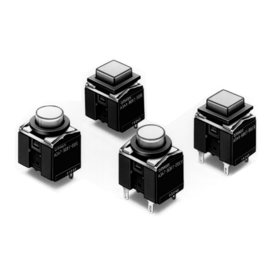
A3A
Lighted Pushbutton Switch
Compact High-capacity
Push-button Switch
●Ideal for use as a high breaking capacity Power
Switch.
●Switches from micro load (minimum applicable load:
5 VDC 1mA) to high capacity load.
RoHS Compliant
Refer to Safety Precautions for All Pushbutton Switches/Indicators
and Safety Precautions on page 8.
List of Models
●Non-lighted Push-button Switches
Appearance
A3AA-9@
Square
@1-00@
A3AT-9@
Round
@1-00@
Model Number Structure
■Model Number Legend (Ordering as a Set)......
(1)
A 3 A
A
(1) Shape of Pushbutton
Symbol
Shape
A
Square
T
Round
(2) Terminal
Symbol
Type
0
Solder
1
PCB
(3) Switch Specifications
Symbol
Operation
A
Momentary
B
Alternate
K
Momentary
L
Alternate
■Specifications: Refer to page 3.
■Accessories: Refer to page 2.
●Lighted Push-button Switches
Model
Illumination
Square
LED
surface
illumination
Round
(2)
(3)
- 9
1 -
0 K
Contact type
(
3 A at 125 VAC,
SPDT
2 A at 30 VDC
(
6 A at 125 VAC,
SPST-NO
2 A at 250 VAC,
4 A at 30 VDC
Appearance
Model
A3AA-9@
@1-00E@
A3AT-9@
@1-00E@
The model numbers used to order sets of Units are illustrated below.
One set comprises the Pushbutton (LED lamp built-in) and Switch.
For information on combinations, refer to Ordering Information.
(4)
(5)
00E R
)
(4) Illumination
Symbol
Operation
)
00
Non-lighted
00E
Surface illumination
■Dimensions: Refer to page 5.
(5) Pushbutton Color
1. Non-lighted Models
Symbol
Pushbutton Color
L
Light gray
R
Red*
Y
Yellow*
G
Green*
A
Blue
B
Black
D
Dark gray
H
Gray
2. LED Surface
Illumination Models
Symbol
Pushbutton Color
R
Red
Y
Yellow
G
Green
* The color is the same for both LED
surface illumination models and
non-lighted models (translucent).
1
A
3
A
Advertisement

Related Manuals for Omron A3A Series


Summary of Contents for Omron A3A Series
- Page 1 Lighted Pushbutton Switch Compact High-capacity Push-button Switch ●Ideal for use as a high breaking capacity Power Switch. ●Switches from micro load (minimum applicable load: 5 VDC 1mA) to high capacity load. RoHS Compliant Refer to Safety Precautions for All Pushbutton Switches/Indicators and Safety Precautions on page 8.
-
Page 2: List Of Models
Lighted Pushbutton Switch List of Models SPST-NO Color symbol for Minimum Appearance Terminal Operation Illumination Model pushbutton packing unit Square/A3AA Non-lighted A3AA-90K1-00@ Momentary LED surface illumination A3AA-90K1-00E@ Solder Non-lighted A3AA-90L1-00@ Alternate LED surface illumination A3AA-90L1-00E@ (Non-lighted) Non-lighted A3AA-91K1-00@ R (red) Momentary Y (yellow) LED surface illumination... -
Page 3: Specifications
Lighted Pushbutton Switch Specifications ■Approved Standards ■Characteristics UL (File No. E41515), CSA (File No. LR45258) Momentary action: 120 operations/minute max. Mechanical Operating Alternate action: 60 operations/minute max. *1 1a: 6 A at 125 VAC, 2 A at 250 VAC, 4 A at 30 VDC frequency 1c: 3 A at 125 VAC, 2 A at 30 VDC Electrical... - Page 4 2. An A3A with solder terminals is provided with a black flange and leaf spring, however an A3A with PCB terminals is not provided with them. If a black flange and leaf spring are required for an A3A with PCB terminals, order them from your OMRON representative. (Refer to page 2.)
- Page 5 Lighted Pushbutton Switch Dimensions (Unit: mm) Non-lighted Model Square Pushbutton SPST-NO SPDT Square push-button @8.9 12.5 12.5 Round Pushbutton Round push-button 15.2 Three, t0.4 terminals Two, t0.4 12.7 terminals 8.9 dia. LED Surface Illumination Models Square Pushbutton SPST-NO SPDT Square push-button @8.9 12.5 12.5...
- Page 6 Lighted Pushbutton Switch ■Terminals Contact Solder terminal PCB terminal LED Surface Non-lighted Models Non-lighted Models Terminal Hole Switch terminal: t0.4 Illumination Models Dimensions LED Surface Illumination Models Switch terminal: t0.4 Switch terminal: t0.4 Switch terminal: t0.4 Lamp terminal: t0.3 Lamp terminal: t0.3 Terminal Arrangement PCB Dimensions (BOTTOM VIEW)
- Page 7 Lighted Pushbutton Switch ■Accessories Dimensions Leaf Spring A3A-200 Flange (Square) A3A-24@ Flange (Round) A3A-25@ 12.7 12.7 dia. 9.1 dia. 12.2 t = 0.3 (10.1) (10.1) 11.6 11.6 Note: Unless otherwise specified, a tolerance of ±0.4 mm applies to all dimensions. ■Panel Cutouts Square Pushbutton For Side-by-side Mounting...
-
Page 8: Precautions For Correct Use
Lighted Pushbutton Switch Precautions ●Refer to the “Push-button Switches/Indicators Common Precautions” for correct use. Precautions for Correct Use ● Pushbutton • Please do not perform wiring or touch Note: Make sure that the limiting resistor connected to the built-in LED of an A3A the charged parts of terminals while •... - Page 9 Lighted Pushbutton Switch ■Installation ● Mounting and Replacing the Pushbutton 1. Mounting Direction for the 2. Removing the Pushbutton (Non-lighted Models Only) Pushbutton and Switch • Insert the catches of the Pushbutton into the • To remove the Pushbutton, hold both the •...
-
Page 10: Regional Contact
Electronic and Mechanical Components Company Regional Contact Americas Europe https://components.omron.com/us-en/ https://components.omron.com/eu-en/ Asia-Pacific China https://components.omron.com/sg-en/ https://components.omron.com.cn/ Korea Japan https://components.omron.com/kr-en/ https://components.omron.com/jp-ja/ © OMRON Corporation 2007-2022 All Rights Reserved. Cat. No. A025-E1-07 In the interest of product improvement, specifications are subject to change without notice. 0322 (0207)