Advertisement
Quick Links
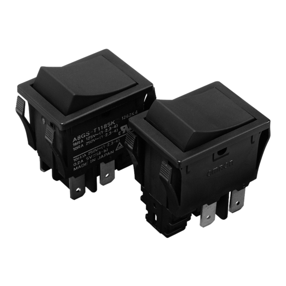
Delay OFF Rocker Switch
A8GS-T
Minimum size class in the industry Remote Reset
Rocker Switch with Delay OFF Function
• Rocker switch with Delay OFF Function. Switch is kept to turn ON,
even if button is operated to turn OFF, and Switch is turned OFF by
external signal.
• Zero standby power with Reset function, switching OFF by external
signal.
• Preventing from application trouble such as a data lost or circuit
damage by forced power OFF.
• Timing control of main power switch turn OFF for safety application
design with Delay OFF function.
• Contact gap of 3 mm minimum.
• UL and cUL standard approved, Conforming to EN standards.
• RoHS Compliant.
* There are 2 kinds of main models A8GS. (Delay OFF Function model and Remote Reset model) With regard to the models with Remote Reset Function, please refer to A8GS datasheet.
Ordering Information
Contact Form
1 to 4: Power contact terminal
a, b: Signal contact terminal
+, -: Coil terminal
Terminals
No Marking
Marking on caps
Note: 1. This is not general 3 pole switch.
(1) Signal contact terminal is only for detecting button ON/OFF.
(2) Power contact terminal is for turning ON/OFF of circuit. Switch is turned OFF by external signal only, after turning OFF of button.
Specifications
■ Contact Ratings
Rated voltage
Power Contact Terminal
Signal Contact Terminal
Note: 1. The above ratings were tested under the following conditions:
(1) Ambient temperature: 20 ± 2 °C
(2) Ambient humidity: 65 ± 5 % RH
(3) Switching frequency: 7 times/min
Signal Contact Terminal: SPST + Power Contact Terminal: DPST
Signal Contact Terminal × 1 + Power Contact Terminal × 2
Signal Contact Terminal: CT Connector
Power Contact Terminal: Quick-connect terminals
#187(t=0.8)
A8GS-T1185K
A8GS-T1285K
A8GS-T1385K
Rated current
(Resistive load)
125 VAC
16 A
250 VAC
10 A
5 VDC
0.2 A
+
1
2
a
b
3
4
-
Signal Contact Terminal: CT Connector
Power Contact Terminal: Solder terminals
A8GS-T1115K
A8GS-T1215K
A8GS-T1315K
■ Contact specifications
Material
Contact gap
Minimum applicable
load (Reference value) *
* Please refer to '' Using Micro loads'' in ''Precautions'' for more information on
the minimum applicable load.
Delay OFF Rocker Switch
Quantity
per box
50
Signal contact
Power contact
Gold alloy
Silver alloy
3 mm
3 mm
3 VDC 1 mA
5 VDC 200 mA
A8GS-T
1
Advertisement

Related Manuals for Omron A8GS-T Series


Summary of Contents for Omron A8GS-T Series
- Page 1 Delay OFF Rocker Switch A8GS-T Minimum size class in the industry Remote Reset Rocker Switch with Delay OFF Function • Rocker switch with Delay OFF Function. Switch is kept to turn ON, even if button is operated to turn OFF, and Switch is turned OFF by external signal.
- Page 2 Note: 1. Voltage for coil should be set within operating voltage range and applied time should be within rated usage cycle. Otherwise the performance of the coil may be deteriorated. 2. In case of applying voltage within the range from 5.5 to 24 VDC to the coil, contact your OMRON sales representative. Characteristics...
-
Page 3: Operation
Operation Delay OFF Function Power contacts are kept in ON status, even if button is operated to turn OFF by manual operation of button. And Switch is turned OFF by external signal to coil embedded in switch. (1) Signal contact terminal and Power contact terminal are turned ON by manual operation of button. (2) Power contact terminal is kept in ON status, even if button is operated to turn OFF by manual operation. - Page 4 Dimensions /Operating Characteristics (Unit: mm) A8GS-T1@85K 19.2 16.5 4.75 15.8±0.8 18.6 CT Connector Operating force (OF) 1.8 ± 1.4 N CT Connector Note: 1. Unless otherwise specified, a tolerance of ± 0.4 mm applies to all dimensions. 2. At initial operation or operation after reset, operating force is increased, due to switch structure. 3.
- Page 5 Precautions Handling !WARNING Do not apply excessive operating force to the switch. Do not wire the switch or touch any terminal of the Do not drop or apply the excessive shock. Switch while power is being supplied. Or it may result Otherwise the switch may be damaged or deformed.
- Page 6 All sales are subject to Omron Electronic Components LLC standard terms and conditions of sale, which can be found at http://www.components.omron.com/components/web/webfiles.nsf/sales_terms.html ALL DIMENSIONS SHOWN ARE IN MILLIMETERS. To convert millimeters into inches, multiply by 0.03937. To convert grams into ounces, multiply by 0.03527.