Advertisement
Quick Links
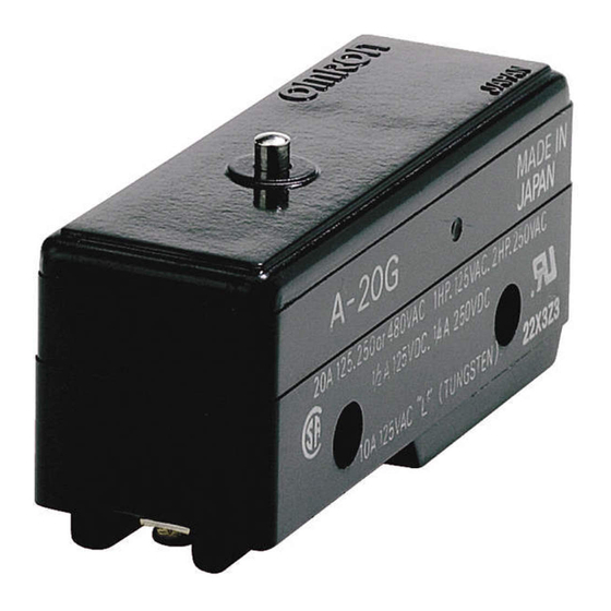
General-purpose Basic Switch
A
High-capacity Switch Capable of Handling
20 A Loads with Large Inrush Currents
• Same shape as OMRON Z Basic Switches except in pin plunger
position, yet endures inrush currents as large as 75 A.
Model Number Structure
■ Model Number Legend
A-20G@-@
1
2 3
4
1. Ratings
20:
20 A (250 VAC)
2. Contact Gap
G:
0.5 mm
3. Actuator
None: Pin plunger
D:
Short spring plunger
Q:
Panel mount plunger
Q21: Panel mount cross roller plunger
Q22: Panel mount roller plunger
V:
Hinge lever
V2:
Hinge roller lever
V21: Short hinge lever
V22: Short hinge roller lever
4. Terminals
None: Solder terminal
B:
Screw terminal (with toothed washer)
General-purpose Basic Switch
A
F-131
Advertisement

Related Manuals for Omron A


Summary of Contents for Omron A
- Page 1 General-purpose Basic Switch High-capacity Switch Capable of Handling 20 A Loads with Large Inrush Currents • Same shape as OMRON Z Basic Switches except in pin plunger position, yet endures inrush currents as large as 75 A. Model Number Structure ■...
-
Page 2: Ordering Information
A-20GV-B Hinge lever A-20GV22 A-20GV22-B Short hinge roller lever A-20GV2 A-20GV2-B Hinge roller lever Note: Refer to Terminals in Model Z for solder and screw terminals. Specifications ■ Approved Standards Agency Standard File No. UL508 E41515 CSA C22.2 No. 55 LR21642 ■... - Page 3 Note: 1. The above values are for steady-state current. 2. Inductive load has a power factor of 0.4 min. (AC) and a time constant of 7 ms max. (DC). 3. Lamp load has an inrush current of 10 times the steady-state current.
-
Page 4: Engineering Data
2. Unless otherwise specified, a tolerance of 0.4 mm applies to all dimensions. ■ Dimensions and Operating Characteristics The models, illustrations, and graphics are for screw-terminal models. (The dimensions for models that are omitted here are the same as for pin- plunger models.) 3.92 to 6.13 N... - Page 5 (2 t 15.6 width across flats) 16.3 Note: 1. Do not use both M12 mounting screw and mounting holes at the same time. 2. Imperfect screw part with a maximum length of 1.5 mm. 6.18 N {630 gf} Panel Mount Roller Plunger max.
- Page 6 Screw Terminals (-B) Solder Terminal 25.4 0.1 11.9 17.45 0.2 17.45 0.2 Three, M4 49.2 Terminal screws (with toothed 49.2 washer) Appropriate terminal screw tightening torque: 0.78 to 1.18 N m {8 to 12 kgf cm}. F-136 General-purpose Basic Switch...
-
Page 7: Mounting Holes
Switch. Tighten the screws to a torque of 1.18 to 1.47 N·m {12 to 15 kgf·cm}. The Switch can be panel mounted, provided that the hexagonal nut of the actuator is tightened to a torque of 2.94 to 4.9 N·m {30 to 50 kgf·cm}. Mounting Holes... - Page 8 ALL DIMENSIONS SHOWN ARE IN MILLIMETERS. To convert millimeters into inches, multiply by 0.03937. To convert grams into ounces, multiply by 0.03527. In the interest of product improvement, specifications are subject to change without notice. Cat. No. B002-E1-07 F-138 General-purpose Basic Switch...